

Pioneer ND-BC20PA - User manual - anglais, espagnol
Pioneer ND-BC20PA - User manual - anglais, espagnol
Pioneer ND-BC20PA - User manual - anglais, espagnol

Create successful ePaper yourself
Turn your PDF publications into a flip-book with our unique Google optimized e-Paper software.
Digital Parking Assistance Camera<br />
Cámara digital de auxilio de estacionamiento<br />
Owner’s Manual<br />
Manual del Propietario<br />
<strong>ND</strong>-<strong>BC20PA</strong><br />
PIONEER CORPORATION<br />
4-1, MEGURO 1-CHOME, MEGURO-KU, TOKYO 153-8654, JAPAN<br />
PIONEER ELECTRONICS (USA) INC.<br />
P.O. Box 1540, Long Beach, California 90801-1540, U.S.A.<br />
TEL: (800) 421-1404<br />
PIONEER EUROPE NV<br />
Haven 1087, Keetberglaan 1, B-9120 Melsele, Belgium<br />
TEL: (0) 3/570.05.11<br />
PIONEER ELECTRONICS ASIACENTRE PTE. LTD.<br />
253 Alexandra Road, #04-01, Singapore 159936<br />
TEL: 65-6472-7555<br />
PIONEER ELECTRONICS AUSTRALIA PTY. LTD.<br />
178-184 Boundary Road, Braeside, Victoria 3195, Australia<br />
TEL: (03) 9586-6300<br />
PIONEER ELECTRONICS OF CANADA, INC.<br />
300 Allstate Parkway, Markham, Ontario L3R 0P2, Canada<br />
TEL: 1-877-283-5901<br />
PIONEER ELECTRONICS DE MEXICO, S.A. de C.V.<br />
Blvd. Manuel Avila Camacho 138 10 piso<br />
Col. Lomas de Chapultepec, Mexico, D.F. 11000<br />
TEL: 55-9178-4270<br />
<br />
ENGLISH<br />
ESPAÑOL<br />
Published by <strong>Pioneer</strong> Corporation.<br />
Copyright © 2007 by <strong>Pioneer</strong> Corporation.<br />
All rights reserved.<br />
Publicado por <strong>Pioneer</strong> Corporation.<br />
Copyright © 2007 <strong>Pioneer</strong> Corporation.<br />
Todos los derechos reservados.<br />
Printed in Japan<br />
Impreso en Japón<br />
E<br />
This device complies with Part 15 of the FCC<br />
Rules.<br />
Operation is subject to the following two<br />
conditions:<br />
(1) This device may not cause harmful interference,<br />
and (2) this device must accept any interference<br />
received, including interference that may cause<br />
undesired operation.<br />
Information to <strong>User</strong><br />
Alteration or modifications carried out without<br />
appropriate authorization may invalidate the user’s<br />
right to operate the equipment.<br />
If you want to dispose this product, do<br />
not mix it with general household waste.<br />
There is a separate collection system for<br />
used electronic products in accordance with<br />
legislation that requires proper treatment,<br />
recovery and recycling.<br />
Private households in the member states of the EU,<br />
in Switzerland and Norway may return their used<br />
electronic products free of charge to designated<br />
collection facilities or to a retailer (if you purchase a<br />
similar new one).<br />
For countries not mentioned above, please contact<br />
your local authorities for the correct method of<br />
disposal.<br />
By doing so you will ensure that your disposed<br />
product undergoes the necessary treatment, recovery<br />
and recycling and thus prevent potential negative<br />
effects on the environment and human health.<br />
WARNING:<br />
Handling the cord on this product or cords associated<br />
with accessories sold with the product may expose<br />
you to chemicals listed on proposition 65 known to<br />
the State of California and other governmental entities<br />
to cause cancer and birth defects or other reproductive<br />
harm. Wash hands after handling.<br />
IMPORTANT<br />
SAFEGUARDS<br />
• Do not wash your car with an automatic car wash<br />
or high-pressure water as it may result in water<br />
entering the camera or the camera falling off.<br />
• Do not attempt to heat the surface of the camera<br />
lens or camera lens itself with a lighter and so on<br />
when they have become frozen. This can cause a<br />
malfunction.<br />
• This product is a rear view camera for checking<br />
the view at the rear of a car.<br />
A rear view camera is a camera that provides symmetrical<br />
images in the same way as rear and side<br />
view mirrors.<br />
En<br />
•<br />
Connection to a TV with an RCA video input is<br />
possible, but confirm whether the TV you use has<br />
a reverse gear connection function.<br />
Direct sunlight or strong light (sunlight reflected<br />
from a bumper etc) on the camera may result in<br />
smear above and below the location where the<br />
light strikes, but this is not a malfunction.<br />
This product is designed to supplement the driver’s<br />
rear view, but the camera images do not show<br />
all dangers and obstacles. Be sure to look behind<br />
you when reversing to confirm the view.<br />
Since this product uses a wide-angle lens, objects<br />
nearby appear wider and objects far away appear<br />
narrower, and distance may seem different than<br />
the actual distance. Always make sure to visually<br />
check behind your car when backing up.<br />
This product is required to be set individually for<br />
each type of vehicle. When reinstalling this product<br />
on a different car such as after purchasing a<br />
different car, always make sure to change the settings<br />
prior to use.<br />
Always drive carefully without relying too much<br />
on this product.<br />
Check camera stand installation before driving.<br />
Are the screws loose?<br />
•<br />
•<br />
•<br />
•<br />
•<br />
•<br />
–<br />
–<br />
•<br />
•<br />
Is the camera stand firmly secured?<br />
If the rear view camera comes loose while you<br />
are driving it may cause an accident.<br />
This device is designed for use ONLY with<br />
<strong>Pioneer</strong> unit with rear camera input. Before continuing<br />
setup, please confirm you are using the<br />
“Reverse mode” to view this screen.<br />
Those <strong>Pioneer</strong> models compatible with the screen<br />
display (guide, menu, etc.) of this product are as<br />
listed below. When combining with other products,<br />
the screen display displayed by the combined<br />
product may be superimposed on the screen display<br />
displayed by this product.<br />
AVIC-Z1 / AVIC-Z2 / AVIC-HD1BT / AVIC-HD3 /<br />
AVIC-D3 / AVH-P5900DVD / AVH-P5950DVD /<br />
AVH-P7900DVD / AVH-P7950DVD<br />
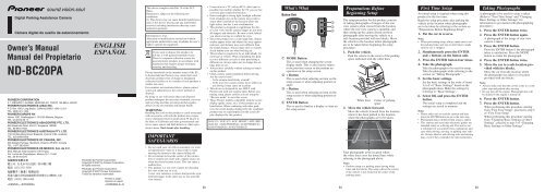
What's What<br />
Button Unit<br />
➁<br />
➂<br />
➃<br />
➀<br />
➀ MODE Button<br />
This is used when changing the screen<br />
display mode. This is also used to return<br />
to the previous screen or discontinue an<br />
operation on the setup screen.<br />
➁ + Button<br />
This is used when selecting an item on the<br />
setup screen or when adjusting position or<br />
angle.<br />
➂ – Button<br />
This is used when selecting an item on the<br />
setup screen or when adjusting position or<br />
angle.<br />
➃ ENTER Button<br />
This is used to finalize a display or item on<br />
the setup screen.<br />
En<br />
Preparations Before<br />
Beginning Setup<br />
The setup procedure for this product consists<br />
of taking photographs of images of the rear<br />
view camera when viewed from the location<br />
where the rear view camera is installed, and<br />
then setting up the camera based on those<br />
photographs after moving the vehicle to a<br />
safe location provided with tire blocks. Move<br />
the vehicle to the location where photographs<br />
are to be taken before beginning the setup<br />
procedure.<br />
1. Park the vehicle.<br />
Park the vehicle in the center of the parking<br />
space indicated with the white lines.<br />
White lines Center of parking<br />
space<br />
2. Move the vehicle forward.<br />
Move the vehicle forward from the location<br />
where it has been parked to the location<br />
where the photographs are to be taken.<br />
Take photographs at the location where<br />
the white lines cross the dotted lines while<br />
referring to the photograph above.<br />
Note:<br />
• Perform setup at a parking space having white<br />
lines and tire blocks. The setup will not be correct<br />
if the vehicle is not located in the center of the<br />
parking space.<br />
First Time Setup<br />
An initial setup is required when using this<br />
product for the first time.<br />
Begin the setup procedure after parking the<br />
vehicle at the location where photographs<br />
are to be taken by referring to the section on<br />
“Preparations Before Beginning Setup”.<br />
1. Put the car in reverse.<br />
Note:<br />
• When performing setup, always make sure to set<br />
the parking brake and step on the brake to make<br />
sure the car is stopped.<br />
2. Simultaneously press the ENTER<br />
and + buttons on the button unit.<br />
3. Press the ENTER button four times.<br />
4. Take the photograph.<br />
Take the photograph to be used for setup.<br />
Take the photograph while referring to the<br />
section on “Taking Photographs”.<br />
5. Set the basic settings.<br />
Set the basic settings in the order of items<br />
A to F of “Basic Settings” based on the<br />
photograph taken. Make the settings by<br />
referring to “Basic Settings”.<br />
6. Select OK and press the ENTER<br />
button.<br />
The initial setup is completed and the<br />
settings are stored in memory.<br />
Note:<br />
•<br />
•<br />
•<br />
Please make sure to read the caution and then<br />
press the ENTER button to go to the next step.<br />
Photograph data is deleted when setup is ended.<br />
This camera and associated electronic guides are<br />
intended solely as a driving aid. This unit is not<br />
a substitute for you attentiveness, judgement, and<br />
care while driving, moving, or parking your vehicle.<br />
Always observe safe driving rules and driving<br />
laws, even if they contradict the unit instructions.<br />
En<br />
Taking Photographs<br />
A photograph to be used for setup is taken.<br />
(Refer to “First Time Setup” and “Changing<br />
Basic Settings or Other Settings” for<br />
information to get started with photographing<br />
procedure.)<br />
1. Press the ENTER button twice.<br />
2. Press the ENTER button again.<br />
A photograph of the image of rear view<br />
camera is taken.<br />
3. Press the ENTER button.<br />
Press the ENTER button if the photograph<br />
taken is satisfactory. Press the MODE<br />
button to retake the photograph.<br />
4. Press the ENTER button twice.<br />
5. Move the car to a safe location provided<br />
with tire blocks.<br />
Move the car from the location where<br />
the photograph was taken to a location<br />
provided with tire blocks.<br />
Note:<br />
• Always make sure that the car has come to a complete<br />
stop and parked after moving.<br />
• Do not turn off the engine. Photograph data will<br />
be deleted if the engine is turned off.<br />
6. Press the ENTER button.<br />
7. Press the ENTER button.<br />
When performing this procedure starting<br />
from “First Time Setup”, proceed to step 5<br />
of “First Time Setup”.<br />
When performing this procedure starting<br />
from “Changing Basic Settings or Other<br />
Settings”, proceed to step 5 of “Changing<br />
Basic Settings or Other Settings”.
Basic Settings<br />
Basic settings refer to those settings that are<br />
mandatory. Basic settings are set during initial<br />
setup. These settings can be changed later.<br />
A. Centerline<br />
Adjust the monitor connected to the rear view<br />
camera. Adjust so that the vehicle centerline is<br />
displayed in the center of the screen.<br />
Note:<br />
• The centerline serves as a reference for vehicle<br />
width when parked (orange line).<br />
1. Press the ENTER button.<br />
2. Adjust so that the centerline is in the<br />
center of the screen using the + and<br />
– buttons.<br />
Adjust so that the number of lines is the<br />
same on both sides of the screen.<br />
Note:<br />
• Adjustment can be made within the range of –63<br />
to +63.<br />
3. Press the ENTER button.<br />
When performing this procedure starting<br />
from “First Time Setup”, proceed to<br />
section B entitled “Position (Rotate)”.<br />
When performing this procedure starting<br />
from “Changing Basic Settings or Other<br />
Settings”, return to step 5 of “Changing<br />
Basic Settings or Other Settings”.<br />
B. Position (Rotate)<br />
Adjust the rotation of the rear view camera<br />
image as viewed from the location where the<br />
rear view camera is installed.<br />
1. Press the ENTER button.<br />
2. Adjust the angle with the + and<br />
– buttons.<br />
Adjust the angle so that an object (such as<br />
the tire blocks) serving as a reference along<br />
the horizontal lines is displayed.<br />
Horizontal lines<br />
Note:<br />
• Adjustment can be made within the range of –511<br />
to +511.<br />
• Some portions may not be able to be seen depending<br />
on the settings.<br />
3. Press the ENTER button.<br />
When performing this procedure starting<br />
from “First Time Setup”, proceed to<br />
section C entitled “Position (Horizontal)”.<br />
When performing this procedure starting<br />
from “Changing Basic Settings or Other<br />
Settings”, return to step 5 of “Changing<br />
Basic Settings or Other Settings”.<br />
C. Position (Horizontal)<br />
Adjust the horizontal of the rear view camera<br />
image as viewed from the location where the<br />
rear view camera is installed.<br />
1. Press the ENTER button.<br />
2. Adjust the horizontal position with<br />
the + and – buttons.<br />
Adjust so that the center of the parking<br />
space is displayed in the center of the<br />
camera screen in the horizontal direction.<br />
3. Press the ENTER button.<br />
When performing this procedure starting<br />
from “First Time Setup”, proceed to<br />
section D entitled “View Diagonal”.<br />
When performing this procedure starting<br />
from “Changing Basic Settings or Other<br />
Settings”, return to step 5 of “Changing<br />
Basic Settings or Other Settings”.<br />
D. View Diagonal<br />
Adjust the inclination of the rear view camera<br />
image as viewed from the location where the<br />
rear view camera is installed.<br />
1. Press the ENTER button.<br />
2. Adjust view diagonal with the + and<br />
– buttons.<br />
Adjust view diagonal so that the white<br />
lines of the parking space are displayed<br />
symmetrically.<br />
Centerline<br />
Note:<br />
• Adjustment can be made within the range of –255<br />
to +255.<br />
3. Press the ENTER button.<br />
When performing this procedure starting<br />
from “First Time Setup”, proceed to<br />
section E entitled “View Angle”.<br />
When performing this procedure starting<br />
from “Changing Basic Settings or Other<br />
Settings”, return to step 5 of “Changing<br />
Basic Settings or Other Settings”.<br />
E. View Angle<br />
Adjust the view angle (high angle mode) as<br />
viewed from directly overhead.<br />
1. Press the ENTER button.<br />
2. Adjust the angle with the + and<br />
– buttons.<br />
Adjust the angle so that the white lines are<br />
aligned with the vertical lines.<br />
Vertical lines<br />
Note:<br />
• Adjustment can be made within the range of –511<br />
to +511.<br />
3. Press the ENTER button.<br />
When performing this procedure starting<br />
from “First Time Setup”, proceed to section<br />
F entitled “Vertical Guideline (Width)”.<br />
When performing this procedure starting<br />
from “Changing Basic Settings or Other<br />
Settings”, return to step 5 of “Changing<br />
Basic Settings or Other Settings”.<br />
F. Vertical Guideline (Width)<br />
Adjust the width within the vertical guidelines.<br />
1. Press the ENTER button.<br />
2. Adjust the position with the + and<br />
– buttons.<br />
Adjust the position using the white lines of<br />
the parking space as a reference.<br />
Vertical guidelines<br />
Note:<br />
• Adjustment can be made within the range of –255<br />
to +255.<br />
3. Press the ENTER button.<br />
4. Press the ENTER button twice.<br />
When performing this procedure starting<br />
from “First Time Setup”, proceed to step 6<br />
of “First Time Setup”.<br />
When performing this procedure starting<br />
from “Changing Basic Settings or Other<br />
Settings”, return to step 5 of “Changing<br />
Basic Settings or Other Settings”.<br />
Changing Basic Settings or<br />
Other Settings<br />
Basic settings set during initial setup can be<br />
changed. In addition, other settings can also<br />
be made such as View (Wide/Zoom) and<br />
Guideline (Shape) on “Advanced Settings”.<br />
Begin the setup procedure after parking the<br />
vehicle at the location where photographs<br />
are to be taken by referring to the section on<br />
“Preparations Before Beginning Setup”.<br />
1. Put the vehicle in reverse.<br />
Note:<br />
• When performing setup, always make sure to set<br />
the parking brake and step on the brake to make<br />
sure the car is stopped.<br />
2. Simultaneously press the ENTER<br />
and + buttons.<br />
3. Press the ENTER button four times.<br />
4. Take the photograph.<br />
Take the photograph to be used for setup.<br />
Take the photograph while referring to the<br />
section on “Taking Photographs”.<br />
5. Select the parameter to be set with<br />
the + and – buttons and then press<br />
the ENTER button.<br />
Basic Settings<br />
Set the basic settings<br />
while referring to<br />
“Basic Settings”.<br />
6. Select OK and press the ENTER<br />
button.<br />
The settings are stored in memory.<br />
Please make sure to read the caution and then<br />
Horizontal direction centerline<br />
press the ENTER button to go to the next step.<br />
• Photograph data is deleted when setup is ended.<br />
Note:<br />
• This camera and associated electronic guides are<br />
• Adjustment can be made within the range of –63<br />
intended solely as a driving aid. This unit is not<br />
to +63.<br />
a substitute for you attentiveness, judgement, and<br />
Note:<br />
care while driving, moving, or parking your vehicle.<br />
• The vertical guidelines (shape) setting reflect the<br />
Always observe safe driving rules and driving<br />
screen display of view angle and vertical guideline<br />
laws, even if they contradict the unit instructions.<br />
(width).<br />
En En En En<br />
Note:<br />
•<br />
Advanced Settings<br />
Set the advanced settings<br />
while referring to<br />
“Advanced Settings”.<br />
Advanced Settings<br />
Advanced settings such as View (Wide/Zoom)<br />
and Guideline (Shape) can be set using<br />
advanced settings.<br />
A. View (Wide/Zoom)<br />
This adjustment is only necessary when only<br />
ground is displayed or when the display is too<br />
small or illegible when viewed with the high<br />
angle mode because of the height of the rear<br />
view camera.<br />
1. Press the ENTER button.<br />
2. Adjust the view elevation with the +<br />
and – buttons.<br />
Note:<br />
• Adjustment can be made within the range of –63<br />
to +63.<br />
3. Press the ENTER button.<br />
Return to step 5 of “Changing Basic<br />
Settings or Other Settings”.<br />
B. Guideline (Shape)<br />
Adjust the inclination of the vehicle vertical<br />
guidelines (shape) when there is a considerable<br />
discrepancy with the vehicle width towards the<br />
back of the field of view.<br />
1. Press the ENTER button.<br />
2. Adjust the angle with the + and<br />
– buttons.<br />
Vertical guidelines<br />
Note:<br />
• Adjustment can be made within the range of –127<br />
to +127.<br />
3. Press the ENTER button.<br />
4. Press the ENTER button twice.<br />
Return to step 5 of “Changing Basic<br />
Settings or Other Settings”.<br />
C. Guideline (Distance)<br />
The distance between the horizontal guidelines<br />
can be adjusted. The horizontal guidelines are<br />
displayed at the interval shown in Fig. 2 during<br />
the initial setup when the camera has been<br />
installed at the position shown in Fig. 1.<br />
Fig. 1<br />
50˚<br />
1.5 m / 5 ft.<br />
Fig. 2<br />
Approx.<br />
2 m / 7 ft.<br />
Approx.<br />
1 m / 3 ft.<br />
Approx.<br />
1 m / 3 ft.<br />
Note:<br />
• The horizontal guidelines consist of three reference<br />
lines that serve as a reference when parking<br />
(green, yellow and red lines).<br />
• In the case the “view angle” of the basic settings<br />
has been adjusted from the factory adjustment,<br />
the distances between the horizontal guidelines as<br />
shown in Fig. 2 (approx. 1 m, 1 m and 2 m) will<br />
be different.<br />
1. Press the ENTER button.<br />
2. Adjust the angle with the + and<br />
– buttons.<br />
Horizontal guidelines<br />
Note:<br />
• Adjustment can be made within the range of –255<br />
to +255.<br />
3. Press the ENTER button.<br />
4. Press the ENTER button twice.<br />
Return to step 5 of “Changing Basic<br />
Settings or Other Settings”.
D. Guideline (On/Off)<br />
This is used to switch the vertical and<br />
horizontal guidelines on and off.<br />
1. Press the ENTER button.<br />
2. Select on or off for the guidelines<br />
with the + and – buttons.<br />
3. Press the ENTER button.<br />
4. Press the ENTER button twice.<br />
Return to step 5 of “Changing Basic<br />
Settings or Other Settings”.<br />
Returning to Default<br />
Settings<br />
The product can be reset to the default settings.<br />
Reset to default settings in the following<br />
situations:<br />
•<br />
•<br />
The position of the camera has changed.<br />
The vehicle on which the camera is installed has<br />
changed.<br />
1. Press the MODE and ENTER buttons<br />
simultaneously.<br />
Note:<br />
• Press the MODE button to cancel resetting to<br />
default settings.<br />
2. Press the ENTER button.<br />
All of the settings are returned to the<br />
default settings.<br />
Screen Display<br />
Two types of screen displays are available with<br />
this product.<br />
Normal Angle Mode:<br />
This is used when displaying the normal rear<br />
view camera image.<br />
Vertical guidelines Horizontal guidelines<br />
High Angle Mode:<br />
This displays the view from directly overhead.<br />
Changing the Screen<br />
Display Mode<br />
1. Press the MODE button when the<br />
rear view camera image is displayed.<br />
The screen display mode changes in the<br />
manner described below each time the<br />
MODE button is pressed.<br />
Normal angle mode ↔ High angle mode<br />
Note:<br />
• The screen display mode returns to the normal<br />
angle mode prior to being changed when the<br />
engine is turned off.<br />
Optional Advanced Setup<br />
Preparation<br />
To improve accuracy, the optional setup will<br />
use a grid of masking tape to provide a visual<br />
representation similar to the on-screen setting<br />
of the system. To complete this procedure,<br />
you will need approximately 54 feet (18 yards)<br />
(16.5 meter) of 2 inch (5 centimeter) wide<br />
masking tape (or wider).<br />
Please see the image below and follow these<br />
steps to complete the procedure:<br />
1) Cut one strip of masking tape equal<br />
to the width of the vehicle. Place the<br />
masking tape on the parking surface<br />
approximately 3 feet (1 meter) from<br />
and parallel to the rear bumper. This<br />
strip of masking tape will be the<br />
indicator used to adjust the RED line in<br />
Advanced Settings – Step C. Guideline<br />
(Distance).<br />
2) Cut two strips of masking tape,<br />
approximately 15 feet (4.5 meter) in<br />
length, and place them on the parking<br />
surface in the position shown in the<br />
image below, parallel to the sides of the<br />
vehicle and extending to the rear. These<br />
strips represent the width of the vehicle,<br />
and will be used instead of the painted<br />
parking lines in both the Basic Settings<br />
and Advanced Settings.<br />
3) Cut one strip of masking tape,<br />
approximately 15 feet (4.5 meter) in<br />
length, and place on the parking surface<br />
from the center of the rear bumper<br />
extending back. This strip will indicate<br />
the centerline of the vehicle and will<br />
be used in both the Basic Settings and<br />
Advanced Settings.<br />
Step 2<br />
Step 3<br />
Step 1<br />
Discrepancies Between Screen<br />
Display and Actual Road Surface<br />
Discrepancies in distance and the course over<br />
which the vehicle is traveling may occur<br />
between the horizontal guidelines on the<br />
screen and actual road surface in the following<br />
situations.<br />
When there is a steep upgrade behind the<br />
vehicle:<br />
The horizontal guidelines serve as a reference<br />
for distance relative to a flat road surface.<br />
Consequently, when there is a steep upgrade<br />
behind the vehicle, the horizontal guidelines<br />
appear closer to you than the actual distances.<br />
For example, in the case of an obstacle present<br />
on a steep upgrade, the obstacle appears to<br />
be farther away than it actually is. Similarly,<br />
discrepancies also occur in the course over<br />
which the vehicle is traveling between the<br />
horizontal guidelines and the actual road<br />
surface.<br />
➀<br />
➁<br />
➀ Horizontal guidelines<br />
➁ Vehicle status<br />
➂ Discrepancy<br />
➂<br />
When there is a steep downgrade behind<br />
the vehicle:<br />
When there is a steep downgrade behind<br />
the vehicle, the horizontal guidelines appear<br />
farther to the rear than the actual distances.<br />
When there is an obstacle present on a steep<br />
downgrade, the obstacle appears to be closer<br />
than it actually is. Similarly, discrepancies also<br />
occur in the course over which the vehicle is<br />
traveling between the horizontal guidelines and<br />
the actual road surface.<br />
➀<br />
➁<br />
➀ Horizontal guidelines<br />
➁ Vehicle status<br />
➂ Discrepancy<br />
When the vehicle is on an incline:<br />
Discrepancies may occur between the display<br />
and the actual distance and course over which<br />
the vehicle is traveling when the vehicle is on<br />
an incline due to the number of passengers or<br />
payload.<br />
➀<br />
➀ Vehicle status<br />
➁ Discrepancy<br />
➁<br />
➂<br />
Specifications<br />
Common Units<br />
Power source ......................................................... DC 14.4 V (allowable range: 10.8 V to 15.1 V)<br />
Grounding system ................................................. Negative ground type<br />
Max. current consumption .................................... Approx. 250 mA<br />
Output image ........................................................ Mirror image (for rear view confirmation)<br />
Video output .......................................................... 1 Vp-p (75 Ω)<br />
External Dimensions<br />
Rear view camera ................................................. 27 (W) × 27 (H) × 26 (D) mm<br />
1 (W) × 1 (H) × 1 (D) in.<br />
Image processing unit power supply ..................... 84 (W) × 20 (H) × 65 (D) mm<br />
3-1/4 (W) × 3/4 (H) × 2-1/2 (D) in.<br />
Button unit ............................................................. 27 (W) × 27 (H) × 13 (D) mm<br />
1 (W) × 1 (H) × 1/2 (D) in.<br />
Weights<br />
Rear view camera ................................................. 150 g (0.3 lbs) (including cable)<br />
Image processing unit power supply ..................... 200 g (0.44 lbs) (including power cord)<br />
Button unit ............................................................. 95 g (0.2 lbs) (including cable)<br />
Camera Unit<br />
Imaging sensor ...................................................... 1/4-inch color CCD sensor<br />
No. of pixels .......................................................... 492 (vertical) × 512 (horizontal)<br />
(total no. of pixels: approx. 270 000, effective<br />
no. of pixels: approx. 250 000)<br />
Lens ....................................................................... Wide-angle, focal length: 1.53 mm, F value: 2.8<br />
Angle of view ....................................................... Horizontal: approx. 135˚, vertical: approx. 100˚<br />
IR cutoff (special vehicle-mounted) filter ............. Provided<br />
Iris system .............................................................. Electronic iris<br />
Scanning system .................................................... Interlace<br />
Synchronizing system ............................................ Internal synchronization<br />
Signal-to-noise ratio .............................................. 40 dB or more<br />
Horizontal resolution ............................................. Approx. 300 TV lines<br />
Illumination range ................................................. Approx. 1.5 lux to 100 000 lux<br />
Operating temperature range ................................. −30 ˚C to +70 ˚C<br />
−22 ˚F to +158 ˚F<br />
Storage temperature range ..................................... −40 ˚C to +85 ˚C<br />
−40 ˚F to +185 ˚F<br />
Note:<br />
• Specifications and the design are subject to possible modification without prior notice due to improvements.<br />
En En En En
Si desea deshacerse de este producto, no<br />
lo mezcle con los residuos generales de su<br />
hogar. De conformidad con la legislación<br />
vigente, existe un sistema de recogida<br />
distinto para los productos electrónicos que<br />
requieren un procedimiento adecuado de<br />
tratamiento, recuperación y reciclado.<br />
Las viviendas privadas en los estados miembros<br />
de la UE, en Suiza y Noruega pueden devolver<br />
gratuitamente sus productos electrónicos usados<br />
en las instalaciones de recolección previstas o bien<br />
en las instalaciones de minoristas (si adquieren un<br />
producto similar nuevo).<br />
En el caso de los países que no se han mencionado<br />
en el párrafo anterior, póngase en contacto con sus<br />
autoridades locales a fin de conocer el método de<br />
eliminación correcto.<br />
Al actuar siguiendo estas instrucciones, se asegurará<br />
de que el producto de desecho se somete a los<br />
procesos de tratamiento, recuperación y reciclaje<br />
necesarios, con lo que se previenen los efectos<br />
negativos potenciales para el entorno y la salud<br />
humana.<br />
PRECAUCIONES DE<br />
ISEGURIDAD IMPORTANTES<br />
• No lave su coche en un túnel de lavado automático<br />
o agua de alta presión, ya que esto puede resultar<br />
en la entrada de agua en la cámara o caída de la<br />
cámara.<br />
• No intente calentar la superficie del objetivo de<br />
la cámara o el propio objetivo de la cámara con<br />
un encendedor o algo similar cuando los mismos<br />
estén congelados. Eso puede causar un fallo de<br />
funcionamiento.<br />
• Este producto es una cámara de vista posterior<br />
para verificar la vista en la parte trasera de un<br />
coche.<br />
Una cámara de vista posterior es una cámara que<br />
provee imágenes simétricas de la misma manera<br />
que los espejos retrovisores o laterales.<br />
• Se puede hacer la conexión a un televisor con<br />
entrada de vídeo RCA, pero compruebe si el<br />
televisor tiene una función de conexión de marcha<br />
atrás.<br />
• La luz directa del sol o luz fuerte (luz del sol<br />
reflejada de un parachoques, etc.) en la cámara<br />
puede producir una mancha por encima y por<br />
debajo de la ubicación donde la luz radia, pero<br />
esto no es un fallo de funcionamiento.<br />
• Este producto ha sido diseñado para complementar<br />
la vista trasera del conductor, pero las imágenes<br />
de la cámara no muestran todos los peligros y<br />
obstáculos. Asegúrese de mirar atrás cuando vaya<br />
de marcha atrás para comprobar la vista.<br />
•<br />
Como este producto emplea un objetivo gran<br />
angular, los objetos cercarnos aparecen más<br />
anchos y los objetos distantes aparecen más<br />
delgados, y la distancia puede parecer diferente de<br />
la distancia real. Asegúrese siempre de comprobar<br />
hacia atrás visualmente cuando conduce el<br />
vehículo en marcha atrás.<br />
Este producto debe ser configurado<br />
individualmente para cada tipo de vehículo.<br />
Cuando reinstale este producto en un vehículo<br />
diferente, como después de comprar un automóvil<br />
diferente, asegúrese siempre de cambiar su<br />
configuración antes de utilizarlo.<br />
Siempre conduzca el vehículo con cuidado sin<br />
atenerse mucho a este producto.<br />
Verifique la instalación del soporte de la cámara<br />
antes de conducir el coche.<br />
¿No están flojos los tornillos?<br />
•<br />
•<br />
•<br />
–<br />
–<br />
•<br />
•<br />
¿Está firmemente fijo el soporte de la cámara?<br />
Si la cámara de vista posterior se afloja<br />
mientras está conduciendo, esto puede causar<br />
un accidente.<br />
Este dispositivo ha sido diseñado para utilización<br />
SOLAMENTE con una unidad <strong>Pioneer</strong> que tenga<br />
una entrada para cámara de vista posterior. Antes<br />
de continuar la configuración, asegúrese de utilizar<br />
el “Modo de marcha atrás” para ver esta pantalla.<br />
A continuación se enumeran los modelos <strong>Pioneer</strong><br />
compatibles con la visualización de pantalla (guía,<br />
menú, etc.) de este producto. Cuando combine con<br />
otros productos, puede que la visualización de la<br />
pantalla que se muestra por el producto combinado<br />
se sobreponga sobre la visualización de la pantalla<br />
que se muestra por este producto.<br />
AVIC-Z1 / AVIC-Z2 / AVIC-HD1BT / AVIC-HD3 /<br />
AVIC-D3 / AVH-P5900DVD / AVH-P5950DVD /<br />
AVH-P7900DVD / AVH-P7950DVD<br />
Qué es que<br />
Unidad de botones<br />
➁<br />
➂<br />
➃<br />
➀<br />
➀ Botón MODE<br />
Se utiliza este botón para cambiar el modo<br />
de visualización de la pantalla. También se<br />
utiliza este botón para volver a la pantalla<br />
anterior o cancelar una operación en la<br />
pantalla de configuración.<br />
➁ Botón+<br />
Se utiliza este botón para seleccionar un<br />
ítem en la pantalla de configuración o para<br />
ajustar la posición o ángulo.<br />
➂ Botón –<br />
Se utiliza este botón para seleccionar un<br />
ítem en la pantalla de configuración o para<br />
ajustar la posición o ángulo.<br />
➃ Botón ENTER<br />
Se utiliza este botón para finalizar una<br />
visualización o ítem en la pantalla de<br />
configuración.<br />
Preparaciones antes de<br />
iniciar la configuración<br />
El procedimiento de configuración para este<br />
producto consta de tomar fotos de imágenes<br />
de la cámara de vista posterior desde la<br />
ubicación donde la cámara de vista posterior<br />
está instalada y, a continuación, configurar la<br />
cámara con base en las fotos después de mover<br />
el vehículo para un lugar seguro provisto con<br />
dos bloques de neumático. Mueva el vehículo<br />
al local donde tomará las fotos antes de iniciar<br />
el procedimiento de configuración.<br />
1. Estacione el vehículo.<br />
Estacione el vehículo en el centro del<br />
espacio de estacionamiento de acuerdo con<br />
las líneas blancas.<br />
Líneas blancas Centro del espacio de<br />
estacionamiento<br />
2. Mueva el vehículo hacia delante.<br />
Mueva el vehículo hacia delante desde el<br />
local donde estaba estacionado hasta el<br />
local donde tomará las fotos.<br />
Tome las fotos en el local donde las<br />
líneas blancas cruzan las líneas de puntos,<br />
refiriéndose a la foto de arriba.<br />
Nota:<br />
• Realice la configuración en un espacio de<br />
estacionamiento con líneas blancas y bloques de<br />
neumático. La configuración no será correcta si no<br />
se localiza el vehículo en el centro del espacio de<br />
estacionamiento.<br />
Configuración por<br />
primera vez<br />
Se requiere una configuración inicial cuando<br />
se utiliza este producto por primera vez. Inicie<br />
el procedimiento de configuración después<br />
de estacionar el vehículo en la ubicación<br />
donde se tomarán las fotos, refiriéndose a<br />
la sección “Preparaciones antes de iniciar la<br />
configuración”.<br />
1. Ponga en vehículo en marcha atrás.<br />
Nota:<br />
• Cuando realice la configuración, asegúrese<br />
siempre de aplicar el freno de estacionamiento<br />
y de pisar el freno para estacionar el vehículo<br />
completamente.<br />
2. Pulse los botones ENTER y + al<br />
mismo tiempo en la unidad de<br />
botones.<br />
3. Pulse el botón ENTER cuatro veces.<br />
4. Tome la foto.<br />
Tome la foto que se utilizará para la<br />
configuración. Tome las fotos refiriéndose<br />
a la sección “Tomada de fotos”.<br />
5. Haga las configuraciones básicas.<br />
Haga las configuraciones básicas en el<br />
orden de A a F de “Configuraciones<br />
básicas” basándose en las fotos tomadas.<br />
Haga las configuraciones refiriéndose a la<br />
sección “Configuraciones básicas”.<br />
6. Seleccione OK y pulse el botón<br />
ENTER.<br />
Se concluye la configuración inicial y<br />
se almacenan las configuraciones en la<br />
memoria.<br />
Nota:<br />
• Asegúrese de leer las precauciones y, a<br />
continuación, pulse el botón ENTER para<br />
proceder al siguiente paso.<br />
• Los datos de las fotos se borran cuando se finaliza<br />
la configuración.<br />
• Esta cámara y las guías electrónicas asociadas<br />
se destinan solamente al propósito de auxilio<br />
de conducción. Esta unidad no es una substituta<br />
a su atención, juzgamiento y cuidado mientras<br />
conduce, traslada o estaciona su vehículo. Observe<br />
siempre las reglas de conducción segura y leyes de<br />
tránsito, aunque contradigan las instrucciones de<br />
la unidad.<br />
Tomada de fotos<br />
Se toman fotos para la configuración.<br />
(Consulte “Configuración por primera vez”<br />
y “Cambio de las configuraciones básicas u<br />
otras configuraciones” para la información para<br />
quedarse listo para el procedimiento de tomada<br />
de foto.)<br />
1. Pulse el botón ENTER dos veces.<br />
2. Pulse el botón ENTER nuevamente.<br />
Se toma una foto de la imagen de la<br />
cámara de vista posterior.<br />
3. Pulse el botón ENTER.<br />
Pulse el botón ENTER si la foto tomada<br />
está satisfactoria. Pulse el botón MODE<br />
para tomar la foto de nuevo.<br />
4. Pulse el botón ENTER dos veces.<br />
5. Mueva el vehículo a un local seguro<br />
provisto con bloques de neumático.<br />
Mueva el vehículo desde el local donde la<br />
foto ha sido tomada a un local provisto con<br />
bloques de neumático.<br />
Nota:<br />
• Asegúrese siempre de que el vehículo esté<br />
completamente parado y estacionado después de<br />
moverlo.<br />
• No apague el motor. Los datos de las fotos se<br />
borrarán si se apaga el motor.<br />
6. Pulse el botón ENTER.<br />
7. Pulse el botón ENTER.<br />
Cuando realice el procedimiento a partir de<br />
“Configuración por primera vez”, proceda<br />
al paso 5 de “Configuración por primera<br />
vez”.<br />
Cuando realice este procedimiento a partir<br />
de “Cambio de las configuraciones básicas<br />
u otras configuraciones”, procesa al paso 5<br />
de “Cambio de las configuraciones básicas<br />
u otras configuraciones”..<br />
Es Es Es
Configuraciones básicas<br />
Las configuraciones básicas refiénrese a las<br />
configuraciones que son obligatorias. Las<br />
configuraciones básicas se ajustan durante la<br />
configuración inicial. Esas configuraciones<br />
pueden cambiarse más tarde.<br />
A. Línea central [Centerline]<br />
Ajuste el monitor conectado a la cámara de<br />
vista posterior. Ajuste de modo que la línea<br />
central del vehículo se visualice en el centro de<br />
la pantalla.<br />
Nota:<br />
• La línea central sirve como una referencia para<br />
la anchura del vehículo cuando el mismo está<br />
estacionado (línea naranja).<br />
1. Pulse el botón ENTER.<br />
2. Ajuste de modo que la línea central<br />
quede en el centro de la pantalla<br />
utilizando los botones + y –.<br />
Ajuste de modo que el número de líneas<br />
sea igual en ambos lados de la pantalla.<br />
Nota:<br />
• Se puede hacer el ajuste dentro del rango de –63<br />
a +63.<br />
3. Pulse el botón ENTER.<br />
Cuando realice este procedimiento a partir<br />
de “Configuración por primera vez”,<br />
proceda a la sección B titulada “Posición<br />
(Rotación)”.<br />
Cuando realice este procedimiento a partir<br />
de “Cambio de las configuraciones básicas<br />
u otras configuraciones”, vuelva al paso 5<br />
de “Cambio de las configuraciones básicas<br />
u otras configuraciones”.<br />
B. Posición (Rotación)<br />
[Position (Rotate)]<br />
Ajuste la rotación de la imagen de la cámara de<br />
vista posterior visto desde la ubicación donde<br />
la cámara de vista posterior está instalada.<br />
1. Pulse el botón ENTER.<br />
2. Ajuste el ángulo con los botones + y<br />
–.<br />
Ajuste el ángulo de modo que se<br />
visualice un objeto (tal como los bloques<br />
de neumático) que se utilice como<br />
una referencia a lo largo de las líneas<br />
horizontales.<br />
Líneas horizontales<br />
Nota:<br />
• Se puede hacer el ajuste dentro del rango de –511<br />
a +511.<br />
• Puede que no se vean algunas partes dependiendo<br />
de las configuraciones.<br />
3. Pulse el botón ENTER.<br />
Cuando realice este procedimiento a partir<br />
de “Configuración por primera vez”,<br />
proceda a la sección C titulada “Posición<br />
(Horizontal)”.<br />
Cuando realice este procedimiento a partir<br />
de “Cambio de las configuraciones básicas<br />
u otras configuraciones”, vuelva al paso 5<br />
de “Cambio de las configuraciones básicas<br />
u otras configuraciones”.<br />
C. Posición (Horizontal)<br />
[Position (Horizontal)]<br />
Ajuste la posición horizontal de la imagen<br />
de la cámara de vista posterior visto desde la<br />
ubicación donde la cámara de vista posterior<br />
está instalada.<br />
1. Pulse el botón ENTER.<br />
2. Ajuste la posición horizontal con los<br />
botones + y –.<br />
Ajuste de modo que el centro del espacio<br />
de estacionamiento se visualice en el centro<br />
de la pantalla de la cámara en la dirección<br />
horizontal.<br />
Línea central en la dirección horizontal<br />
Nota:<br />
• Se puede hacer el ajuste dentro del rango de –63<br />
a +63.<br />
3. Pulse el botón ENTER.<br />
Cuando realice este procedimiento a partir<br />
de “Configuración por primera vez”,<br />
proceda a la sección D titulada “Diagonal<br />
de visión”.<br />
Cuando realice este procedimiento a partir<br />
de “Cambio de las configuraciones básicas<br />
u otras configuraciones”, vuelva al paso 5<br />
de “Cambio de las configuraciones básicas<br />
u otras configuraciones”.<br />
D. Diagonal de visión [View Diagonal]<br />
Ajuste la inclinación de la imagen de la cámara<br />
de vista posterior visto desde la ubicación<br />
donde la cámara de vista posterior está<br />
instalada.<br />
1. Pulse el botón ENTER.<br />
2. Ajuste la diagonal de visión con los<br />
botones + y –.<br />
Ajuste la diagonal de visión de modo<br />
que las líneas blancas del espacio<br />
de estacionamiento se visualicen<br />
simétricamente.<br />
Nota:<br />
• Se puede hacer el ajuste dentro del rango de –255<br />
a +255.<br />
3. Pulse el botón ENTER.<br />
Cuando realice este procedimiento a partir<br />
de “Configuración por primera vez”,<br />
proceda a la sección E titulada “Ángulo de<br />
visión”.<br />
Cuando realice este procedimiento a partir<br />
de “Cambio de las configuraciones básicas<br />
u otras configuraciones”, vuelva al paso 5<br />
de “Cambio de las configuraciones básicas<br />
u otras configuraciones”.<br />
E. Ángulo de visión [View Angle]<br />
Ajuste el ángulo de visión (modo de ángulo<br />
alto) visto directamente desde arriba.<br />
1. Pulse el botón ENTER.<br />
2. Ajuste el ángulo con los botones + y<br />
–.<br />
Ajuste el ángulo de modo que las líneas<br />
blancas se alineen con las líneas verticales.<br />
Líneas verticales<br />
Nota:<br />
• Se puede hacer el ajuste dentro del rango de –511<br />
a +511.<br />
3. Pulse el botón ENTER.<br />
Cuando realice este procedimiento a partir<br />
de “Configuración por primera vez”,<br />
proceda a la sección F titulada “Línea de<br />
guía vertical (Anchura)”.<br />
Cuando realice este procedimiento a partir<br />
de “Cambio de las configuraciones básicas<br />
u otras configuraciones”, vuelva al paso 5<br />
de “Cambio de las configuraciones básicas<br />
u otras configuraciones”.<br />
F. Línea de guía vertical (Anchura)<br />
[Vertical Guideline (Width)]<br />
Ajuste la anchura dentro de las líneas de guía<br />
verticales.<br />
1. Pulse el botón ENTER.<br />
2. Ajuste la posición con los botones +<br />
y – .<br />
Ajuste la posición utilizando las líneas<br />
blancas del espacio de estacionamiento<br />
como una referencia.<br />
Líneas de guía verticales<br />
Nota:<br />
• Se puede hacer el ajuste dentro del rango de –255<br />
a +255.<br />
3. Pulse el botón ENTER.<br />
4. Pulse el botón ENTER dos veces.<br />
Cuando realice el procedimiento a partir de<br />
“Configuración por primera vez”, proceda<br />
al paso 6 de “Configuración por primera<br />
vez”.<br />
Cuando realice este procedimiento a partir<br />
de “Cambio de las configuraciones básicas<br />
u otras configuraciones”, vuelva al paso 5<br />
de “Cambio de las configuraciones básicas<br />
u otras configuraciones”.<br />
Cambio de las configuraciones<br />
básicas u otras configuraciones<br />
Se puede cambiar las configuraciones<br />
básicas hechas durante la configuración<br />
inicial. Además, también se puede hacer<br />
otras configuraciones como para la Vista<br />
(Ancha/Zoom) y Líneas de guía (Forma) en<br />
“Configuraciones avanzadas”.<br />
Inicie el procedimiento de configuración<br />
después de estacionar el vehículo en la<br />
ubicación donde se tomarán las fotos,<br />
refiriéndose a la sección “Preparaciones antes<br />
de iniciar la configuración”.<br />
1. Ponga en vehículo en marcha atrás.<br />
Nota:<br />
• Cuando realice la configuración, asegúrese<br />
siempre de aplicar el freno de estacionamiento<br />
y de pisar el freno para estacionar el vehículo<br />
completamente.<br />
2. Pulse los botones ENTER y + al<br />
mismo tiempo.<br />
3. Pulse el botón ENTER cuatro veces.<br />
4. Tome la foto.<br />
Tome la foto que se utilizará para la<br />
configuración. Tome las fotos refiriéndose<br />
a la sección “Tomada de fotos”.<br />
5. Seleccione el parámetro que<br />
desee ajustar con los botones + y<br />
– y, a continuación, pulse el botón<br />
ENTER.<br />
Configuraciones<br />
básicas<br />
Haga las<br />
configuraciones<br />
básicas refiriéndose<br />
a la sección<br />
“Configuraciones<br />
básicas”.<br />
Configuraciones<br />
avanzadas<br />
Haga las configuraciones<br />
avanzadas refiriéndose<br />
a la sección<br />
“Configuraciones<br />
avanzadas”.<br />
6. Seleccione OK y pulse el botón<br />
ENTER.<br />
Las configuraciones se almacenan en la<br />
memoria.<br />
Nota:<br />
• Asegúrese de leer las precauciones y, a<br />
continuación, pulse el botón ENTER para<br />
proceder al siguiente paso.<br />
• Los datos de las fotos se borran cuando se finaliza<br />
la configuración.<br />
• Esta cámara y las guías electrónicas asociadas<br />
se destinan solamente al propósito de auxilio<br />
de conducción. Esta unidad no es una substituta<br />
a su atención, juzgamiento y cuidado mientras<br />
conduce, traslada o estaciona su vehículo. Observe<br />
siempre las reglas de conducción segura y leyes de<br />
tránsito, aunque contradigan las instrucciones de<br />
la unidad.<br />
Configuraciones avanzadas<br />
Se puede realizar las configuraciones<br />
avanzadas como Vista (Ancha/Zoom) y Líneas<br />
de guía (Forma) utilizando las configuraciones<br />
avanzadas.<br />
A. Vista (Ancha/Zoom)<br />
[View (Wide/Zoom)]<br />
Este ajuste sólo es necesario cuando se<br />
visualiza solamente el suelo o cuando la<br />
visualización es muy pequeña o ilegible cuando<br />
se ve con el modo de ángulo alto debido a la<br />
altura de la cámara de vista posterior.<br />
1. Pulse el botón ENTER.<br />
2. Ajuste la elevación de visión con los<br />
botones + y –.<br />
Nota:<br />
• Se puede hacer el ajuste dentro del rango de –63<br />
a +63.<br />
3. Pulse el botón ENTER.<br />
Vuelva al paso 5 de “Cambio de<br />
las configuraciones básicas u otras<br />
configuraciones”.<br />
B. Línea de guía (Forma)<br />
[Guideline (Shape)]<br />
Ajuste la inclinación de las líneas de guía<br />
verticales (forma) del vehículo cuando hay una<br />
discrepancia considerable con la anchura del<br />
vehículo hacia atrás del campo de visión.<br />
1. Pulse el botón ENTER.<br />
2. Ajuste el ángulo con los botones + y –.<br />
Líneas de guía verticales<br />
Nota:<br />
• Se puede hacer el ajuste dentro del rango de –127<br />
a +127.<br />
3. Pulse el botón ENTER.<br />
4. Pulse el botón ENTER dos veces.<br />
Vuelva al paso 5 de “Cambio de<br />
las configuraciones básicas u otras<br />
configuraciones”.<br />
Nota:<br />
• La configuración de las líneas de guía verticales<br />
(forma) refleja la visualización de pantalla del<br />
ángulo de visión y la línea de guía vertical<br />
(anchura).<br />
C. Línea de guía (Distancia)<br />
[Guideline (Distance)]<br />
Se puede ajustar la distancia entre las líneas<br />
de guía horizontales. Las líneas de guía<br />
horizontales se visualizan en el intervalo que se<br />
muestra en la Fig. 2 durante la configuración<br />
inicial cuando se ha instalado la cámara en la<br />
posición que se muestra en la Fig. 1.<br />
Fig. 1<br />
50˚<br />
1,5 m<br />
Fig. 2<br />
Aprox.<br />
2 m<br />
Aprox.<br />
1 m<br />
Aprox.<br />
1 m<br />
Línea central<br />
(Continúa en la parte izquierda a continuación.)<br />
Es Es Es Es
Nota:<br />
• Las líneas de guía horizontales constan de<br />
tres líneas de referencia que sirven como una<br />
referencia cuando se estaciona (líneas verde,<br />
amarilla y roja).<br />
• Cuando el “ángulo de visión” de las<br />
configuraciones básicas ha sido ajustado desde<br />
el ajuste de fábrica, las distancias entre las líneas<br />
de guía horizontales que se muestran en la Fig. 2<br />
(aprox. 1 m, 1 m y 2 m) serán diferentes.<br />
1. Pulse el botón ENTER.<br />
2. Ajuste el ángulo con los botones + y<br />
–.<br />
Líneas de guía horizontales<br />
Nota:<br />
• Se puede hacer el ajuste dentro del rango de –255<br />
a +255.<br />
3. Pulse el botón ENTER.<br />
4. Pulse el botón ENTER dos veces.<br />
Vuelva al paso 5 de “Cambio de<br />
las configuraciones básicas u otras<br />
configuraciones”.<br />
D. Línea de guía (Activar/Desactivar)<br />
[Guideline (On/Off)]<br />
Se utiliza esto para activar y desactivar las<br />
líneas de guía horizontales y verticales.<br />
1. Pulse el botón ENTER.<br />
2. Active o desactive las líneas de guía<br />
con los botones + y –.<br />
3. Pulse el botón ENTER.<br />
4. Pulse el botón ENTER dos veces.<br />
Vuelva al paso 5 de “Cambio de<br />
las configuraciones básicas u otras<br />
configuraciones”.<br />
Retorno a las<br />
configuraciones originales<br />
Se puede restaurar el producto a sus<br />
configuraciones originales. Restaure las<br />
configuraciones originales en las siguientes<br />
situaciones:<br />
•<br />
•<br />
Se ha cambiado la posición de la cámara.<br />
Se ha cambiado el vehículo en el cual la cámara<br />
está instalada.<br />
1. Pulse los botones MODE y ENTER<br />
al mismo tiempo.<br />
Nota:<br />
• Pulse el botón MODE para cancelar la<br />
restauración a las configuraciones originales.<br />
2. Pulse el botón ENTER.<br />
Todas las configuraciones volverán a sus<br />
selecciones iniciales.<br />
Visualización de la pantalla<br />
Hay dos tipos de visualizaciones de pantalla<br />
disponibles con este producto.<br />
Modo de ángulo normal:<br />
Se utiliza cuando se visualiza la imagen normal<br />
de la cámara de vista posterior.<br />
Líneas de guía Líneas de guía horizontales<br />
Modo de ángulo alto:<br />
Esto visualiza la vista directamente de arriba.<br />
Cambio del modo de<br />
visualización de la pantalla<br />
1. Pulse el botón MODE cuando se<br />
visualiza la imagen de la cámara de<br />
vista posterior.<br />
El modo de visualización de la pantalla<br />
cambia como se describe a continuación<br />
cada vez que se pulsa el botón MODE.<br />
Modo de ángulo normal ↔ Modo de<br />
ángulo alto<br />
Nota:<br />
• El modo de visualización de la pantalla vuelve<br />
al modo de ángulo normal seleccionado<br />
anteriormente cuando se apaga el motor.<br />
Preparación para la configuración<br />
avanzada opcional<br />
Para mejorar la precisión, la configuración<br />
opcional utiliza una rejilla con una cinta<br />
de enmascaramiento para proveer una<br />
representación visual similar a la configuración<br />
en la pantalla del sistema. Para completar este<br />
procedimiento, se requiere aproximadamente<br />
una cinta de enmascaramiento de 16,5 metros<br />
de largo y 5 centímetros de ancho (o más<br />
ancha).<br />
Vea la imagen a continuación y siga los pasos<br />
para completar el procedimiento.<br />
1) Corte una tira de la cinta de<br />
enmascaramiento que corresponda a la<br />
anchura del vehículo. Coloque la cinta<br />
de enmascaramiento en la superficie de<br />
estacionamiento aproximadamente 1<br />
metro desde y paralela al parachoques<br />
trasero. Se utilizará esta tira de la<br />
cinta de enmascaramiento como el<br />
indicador para ajustar la línea ROJA en<br />
Configuraciones avanzadas – Paso C.<br />
Línea de guía (Distancia).<br />
2) Corte dos tiras de la cinta de<br />
enmascaramiento de aproximadamente<br />
4,5 metros de largo, y colóquelas en<br />
la superficie de estacionamiento en la<br />
posición que se muestra en la imagen<br />
a continuación, paralelas a los lados<br />
del vehículo y se extendiendo hacia la<br />
parte trasera. Esas tiras representan la<br />
anchura del vehículo y se utilizarán en<br />
lugar de las líneas de estacionamiento<br />
pintadas en las Configuraciones básicas<br />
y Configuraciones avanzadas.<br />
3) Corte una tira de la cinta de<br />
enmascaramiento de aproximadamente<br />
4,5 metros de largo, y colóquela en la<br />
superficie de estacionamiento desde<br />
el centro del parachoques trasero, se<br />
extendiendo hacia atrás. Esa tira indicará<br />
la línea central del vehículo y se utilizará<br />
en las Configuraciones básicas y<br />
Configuraciones avanzadas.<br />
Paso 2<br />
Paso 3<br />
Paso 1<br />
Discrepancias entre la visualización de la<br />
pantalla y la superficie de la carretera real<br />
Puede que ocurran discrepancias en la distancia<br />
y camino sobre el cual el vehículo está<br />
viajando entre las líneas de guía horizontales<br />
en la pantalla y la superficie de la carretera real<br />
en las siguientes situaciones.<br />
Cuando hay una cuesta arriba empinada<br />
por detrás del vehículo:<br />
Las líneas de guía horizontales sirven como<br />
una referencia para la distancia relativa<br />
a la superficie de la carretera llana. En<br />
consecuencia, cuando hay una cuesta arriba<br />
empinada por detrás del vehículo, las líneas<br />
de guía horizontales aparecen más cercanas<br />
de que en las distancias reales. Por ejemplo,<br />
cuando hay un obstáculo en una cuesta arriba<br />
empinada, el obstáculo aparece más lejano<br />
de que está realmente. Similarmente, también<br />
ocurren distancias en el curso sobre el cual el<br />
vehículo está viajando entre las líneas de guía<br />
horizontales y la superficie de la carretera real.<br />
➀<br />
➁<br />
➀ Líneas de guía horizontales<br />
➁ Estado del vehículo<br />
➂ Discrepancia<br />
➂<br />
Cuando hay una cuesta abajo empinada<br />
por detrás del vehículo:<br />
Cuando hay una cuesta abajo empinada<br />
por detrás del vehículo, las líneas de guía<br />
horizontales aparecen más lejanas de que en<br />
las distancias reales. Cuando hay un obstáculo<br />
en una cuesta abajo empinada, el obstáculo<br />
aparece estar más cercano de que realmente<br />
está. Similarmente, también ocurren distancias<br />
en el curso sobre el cual el vehículo está<br />
viajando entre las líneas de guía horizontales y<br />
la superficie de la carretera real.<br />
➀<br />
➁<br />
➀ Líneas de guía horizontales<br />
➁ Estado del vehículo<br />
➂ Discrepancia<br />
Cuando el vehículo está inclinado:<br />
Puede que ocurran discrepancias entre la<br />
visualización y la distancia real y el curso<br />
sobre el cual el vehículo está viajando cuando<br />
el vehículo está inclinado debido al número<br />
pasajeros o carga.<br />
➀<br />
➀ Estado del vehículo<br />
➁ Discrepancia<br />
➁<br />
➂<br />
Especificaciones<br />
Unidades comunes<br />
Fuente de alimentación .......................................... CC 14,4 V (rango permisible: 10,8 V a 15,1 V)<br />
Sistema de conexión a tierra .................................. Tipo de conexión a tierra negativa<br />
Consumo de corriente máx. ................................... Aprox. 250 mA<br />
Imagen de salida .................................................... Imagen de espejo (para confirmación de vista<br />
posterior)<br />
Salida de vídeo ....................................................... 1 Vp-p (75 Ω)<br />
Dimensiones externas<br />
Cámara de vista posterior ...................................... 27 (An.) × 27 (Al.) × 26 (Pr.) mm<br />
Fuente de energía de la unidad de procesamiento<br />
de imagen ............................................................... 84 (An.) × 20 (Al.) × 65 (Pr.) mm<br />
Unidad de botones ................................................. 27 (An.) × 27 (Al.) × 13 (Pr.) mm<br />
Pesos<br />
Cámara de vista posterior ...................................... 150 g (incluyendo el cable)<br />
Fuente de energía de la unidad de procesamiento de imagen<br />
................................................................... 200 g (incluyendo el cable de alimentación)<br />
Unidad de botones ................................................. 95 g (incluyendo el cable)<br />
Unidad de la cámara<br />
Sensor de imagen ................................................... Sensor CCD de color de 1/4 pulgadas<br />
Nº de píxeles .......................................................... 492 (vertical) × 512 (horizontal)<br />
(No. total de píxeles: aprox. 270 000,<br />
Nº efectivo de píxeles: aprox. 250 000)<br />
Lente ...................................................................... Gran angular, distancia focal: 1,53 mm,<br />
valor F: 2.8<br />
Ángulo de visión .................................................... Horizontal: aprox. 135°, vertical: aprox. 100°<br />
Filtro de corte IR (especial montado en el vehículo)<br />
................................................................... Suministrado<br />
Sistema de diafragma ............................................ Diafragma electrónico<br />
Sistema de escaneo ................................................ Entrelazado<br />
Sistema de sincronización ...................................... Sincronización interna<br />
Relación señal/ruido ............................................. 40 dB o superior<br />
Resolución horizontal ............................................ Aprox. 300 líneas de TV<br />
Rango de iluminación ............................................ Aprox. 1,5 lux a 100 000 lux<br />
Rango de temperatura de funcionamiento ............. −30 °C a +70 °C<br />
Rango de temperatura de almacenamiento ............ −40 °C a +85 °C<br />
Nota:<br />
• Las especificaciones y el diseño están sujetos a posibles modificaciones sin previo aviso debido a<br />
mejoramientos.<br />
Es Es Es Es


