

Makita Perceuse visseuse 18 V Li-Ion Ø 13 mm (Machine seule) - DDF482Z - Notice
Makita Perceuse visseuse 18 V Li-Ion Ø 13 mm (Machine seule) - DDF482Z - Notice
Makita Perceuse visseuse 18 V Li-Ion Ø 13 mm (Machine seule) - DDF482Z - Notice

Create successful ePaper yourself
Turn your PDF publications into a flip-book with our unique Google optimized e-Paper software.
Reversing switch action<br />
► Fig.6: 1. Reversing switch lever<br />
Speed change<br />
► Fig.7: 1. Speed change lever<br />
CAUTION: Always check the direction of<br />
rotation before operation.<br />
CAUTION: Use the reversing switch only after<br />
the tool comes to a complete stop. Changing the<br />
direction of rotation before the tool stops may damage<br />
the tool.<br />
CAUTION: When not operating the tool,<br />
always set the reversing switch lever to the neutral<br />
position.<br />
This tool has a reversing switch to change the direction<br />
of rotation. Depress the reversing switch lever from the<br />
A side for clockwise rotation or from the B side for counterclockwise<br />
rotation.<br />
When the reversing switch lever is in the neutral position,<br />
the switch trigger cannot be pulled.<br />
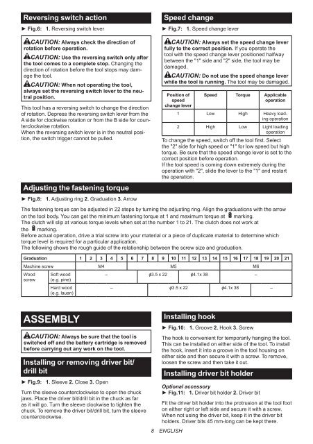
Adjusting the fastening torque<br />
► Fig.8: 1. Adjusting ring 2. Graduation 3. Arrow<br />
CAUTION: Always set the speed change lever<br />
fully to the correct position. If you operate the<br />
tool with the speed change lever positioned halfway<br />
between the "1" side and "2" side, the tool may be<br />
damaged.<br />
CAUTION: Do not use the speed change lever<br />
while the tool is running. The tool may be damaged.<br />
Position of<br />
speed<br />
change lever<br />
Speed Torque Applicable<br />
operation<br />
1 Low High Heavy loading<br />
operation<br />
2 High Low <strong>Li</strong>ght loading<br />
operation<br />
To change the speed, switch off the tool first. Select<br />
the "2" side for high speed or "1" for low speed but high<br />
torque. Be sure that the speed change lever is set to the<br />
correct position before operation.<br />
If the tool speed is coming down extremely during the<br />
operation with "2", slide the lever to the "1" and restart<br />
the operation.<br />
The fastening torque can be adjusted in 22 steps by turning the adjusting ring. Align the graduations with the arrow<br />
on the tool body. You can get the minimum fastening torque at 1 and maximum torque at marking.<br />
The clutch will slip at various torque levels when set at the number 1 to 21. The clutch does not work at<br />
the marking.<br />
Before actual operation, drive a trial screw into your material or a piece of duplicate material to determine which<br />
torque level is required for a particular application.<br />
The following shows the rough guide of the relationship between the screw size and graduation.<br />
Graduation 1 2 3 4 5 6 7 8 9 10 11 12 <strong>13</strong> 14 15 16 17 <strong>18</strong> 19 20 21<br />
<strong>Machine</strong> screw M4 M5 M6<br />
Wood Soft wood<br />
– ɸ3.5 x 22 ɸ4.1x 38 –<br />
screw (e.g. pine)<br />
Hard wood<br />
(e.g. lauan)<br />
– ɸ3.5 x 22 ɸ4.1x 38 –<br />
ASSEMBLY<br />
CAUTION: Always be sure that the tool is<br />
switched off and the battery cartridge is removed<br />
before carrying out any work on the tool.<br />
Installing or removing driver bit/<br />
drill bit<br />
► Fig.9: 1. Sleeve 2. Close 3. Open<br />
Turn the sleeve counterclockwise to open the chuck<br />
jaws. Place the driver bit/drill bit in the chuck as far<br />
as it will go. Turn the sleeve clockwise to tighten the<br />
chuck. To remove the driver bit/drill bit, turn the sleeve<br />
counterclockwise.<br />
Installing hook<br />
► Fig.10: 1. Groove 2. Hook 3. Screw<br />
The hook is convenient for temporarily hanging the tool.<br />
This can be installed on either side of the tool. To install<br />
the hook, insert it into a groove in the tool housing on<br />
either side and then secure it with a screw. To remove,<br />
loosen the screw and then take it out.<br />
Installing driver bit holder<br />
Optional accessory<br />
► Fig.11: 1. Driver bit holder 2. Driver bit<br />
Fit the driver bit holder into the protrusion at the tool foot<br />
on either right or left side and secure it with a screw.<br />
When not using the driver bit, keep it in the driver bit<br />
holders. Driver bits 45 <strong>mm</strong>-long can be kept there.<br />
8 ENGLISH


