

Makita Découpeur-ponceur multifonctions 10,8 V Li-ion 2 Ah ( kit d'accessoires) - TM30DSAEX1 - Notice
Makita Découpeur-ponceur multifonctions 10,8 V Li-ion 2 Ah ( kit d'accessoires) - TM30DSAEX1 - Notice
Makita Découpeur-ponceur multifonctions 10,8 V Li-ion 2 Ah ( kit d'accessoires) - TM30DSAEX1 - Notice

You also want an ePaper? Increase the reach of your titles
YUMPU automatically turns print PDFs into web optimized ePapers that Google loves.
Battery protect<strong>ion</strong> system<br />
The tool is equipped with a battery protect<strong>ion</strong> system.<br />
This system automatically cuts off power to the motor to<br />
extend battery life.<br />
The tool will automatically stop during operat<strong>ion</strong> if the<br />
tool and/or battery are placed under one of the following<br />
condit<strong>ion</strong>s:<br />
Overloaded:<br />
The tool is operated in a manner that causes it to draw<br />
an abnormally high current.<br />
In this situat<strong>ion</strong>, turn the tool off and stop the applicat<strong>ion</strong><br />
that caused the tool to become overloaded. Then turn<br />
the tool on to restart.<br />
If the tool does not start, the battery is overheated. In<br />
this situat<strong>ion</strong>, let the battery cool before turning the tool<br />
on again.<br />
Low battery voltage:<br />
The remaining battery capacity is too low and the tool<br />
will not operate. If you turn the tool on, the motor runs<br />
again but stops soon. In this situat<strong>ion</strong>, remove and<br />
recharge the battery.<br />
Indicating the remaining battery<br />
capacity<br />
Only for battery cartridges with "B" at the end of the<br />
model number<br />
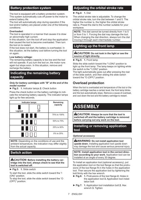
► Fig.2: 1. Indicator lamps 2. Check button<br />
Press the check button on the battery cartridge to indicate<br />
the remaining battery capacity. The indicator lamps<br />
light up for few seconds.<br />
Adjusting the orbital stroke rate<br />
► Fig.4: 1. Dial<br />
The orbital stroke rate is adjustable. To change the<br />
orbital stroke rate, turn the dial between 1 and 5. The<br />
higher the number is, the higher the orbital stroke<br />
rate is. Preset the dial to the number suitable for your<br />
workpiece.<br />
NOTE: The dial cannot be turned directly from 1 to 5<br />
or from 5 to 1. Forcing the dial may damage the tool.<br />
When changing the dial direct<strong>ion</strong>, always turn the dial<br />
moving it through each intermediate number.<br />
<strong>Li</strong>ghting up the front lamp<br />
CAUTION: Do not look in the light or see the<br />
source of light directly.<br />
► Fig.5: 1. Front lamp<br />
Slide the slide switch toward the "I (ON)" posit<strong>ion</strong> to<br />
light up the front lamp. The lamp keeps on lighting while<br />
the switch is the "I (ON)" posit<strong>ion</strong>.<br />
The light automatically goes out after pressing the rear<br />
of the slide switch, and then sliding the slide switch<br />
toward the "O (OFF)" posit<strong>ion</strong>.<br />
Overload protect<strong>ion</strong><br />
When the tool is overloaded and temperature of the tool or the<br />
battery cartridge reaches a certain level, the front lamp blinks<br />
and the tool automatically stops. Remove a cause of overload,<br />
and cool down the tool and the battery cartridge to restart.<br />
<strong>Li</strong>ghted<br />
Indicator lamps<br />
Off<br />
Remaining<br />
capacity<br />
75% to <strong>10</strong>0%<br />
50% to 75%<br />
25% to 50%<br />
0% to 25%<br />
ASSEMBLY<br />
CAUTION: Always be sure that the tool is<br />
switched off and the battery cartridge is removed<br />
before carrying out any work on the tool.<br />
Installing or removing applicat<strong>ion</strong><br />
tool<br />
Opt<strong>ion</strong>al accessory<br />
NOTE: Depending on the condit<strong>ion</strong>s of use and the<br />
ambient temperature, the indicat<strong>ion</strong> may differ slightly<br />
from the actual capacity.<br />
Switch act<strong>ion</strong><br />
CAUTION: Before installing the battery cartridge<br />
into the tool, always check to see that the<br />
tool is switched off.<br />
► Fig.3: 1. Slide switch<br />
To start the tool, slide the slide switch toward the “I<br />
(ON)” posit<strong>ion</strong>.<br />
To stop the tool, slide the slide switch toward the “O<br />
(OFF)” posit<strong>ion</strong>.<br />
WARNING: Do not install applicat<strong>ion</strong> tool<br />
upside down. Installing applicat<strong>ion</strong> tool upside down<br />
may damage the tool and cause serious personal injury.<br />
NOTE: Install applicat<strong>ion</strong> tool in the correct direct<strong>ion</strong><br />
according to your work. Applicat<strong>ion</strong> tool can be<br />
installed at an angle of every 30 degree.<br />
To Install an applicat<strong>ion</strong> tool (opt<strong>ion</strong>al accessory), put<br />
the applicat<strong>ion</strong> tool on the tool flange so that the protrus<strong>ion</strong>s<br />
of the tool flange fit in the holes in the applicat<strong>ion</strong><br />
tool. Then secure the applicat<strong>ion</strong> tool by tightening the<br />
bolt firmly with the hex wrench.<br />
► Fig.6: 1. Protrus<strong>ion</strong>s of the tool flange 2. Holes in<br />
the applicat<strong>ion</strong> tool 3. Applicat<strong>ion</strong> tool installat<strong>ion</strong><br />
bolt<br />
► Fig.7: 1. Applicat<strong>ion</strong> tool installat<strong>ion</strong> bolt 2. Hex<br />
wrench 3. Tighten<br />
7 ENGLISH


