

Sony CDX-GT450U - CDX-GT450U Guide d'installation
Sony CDX-GT450U - CDX-GT450U Guide d'installation
Sony CDX-GT450U - CDX-GT450U Guide d'installation

You also want an ePaper? Increase the reach of your titles
YUMPU automatically turns print PDFs into web optimized ePapers that Google loves.
Face the hook inwards.<br />
Der Haken muss nach innen<br />
weisen.<br />
Tournez le crochet vers<br />
l’intérieur.<br />
Con il gancetto rivolto verso<br />
l’interno.<br />
Het haakje moet naar binnen<br />
wijzen.<br />
<br />
<br />
Power connection diagram<br />
Auxiliary power connector may vary depending on the<br />
car. Check your car’s auxiliary power connector diagram<br />
to make sure the connections match correctly. There are<br />
three basic types (illustrated below). You may need to<br />
switch the positions of the red and yellow leads in the car<br />
stereo’s power supply lead.<br />
After matching the connections and switched power<br />
supply leads correctly, connect the unit to the car’s power<br />
supply. If you have any questions and problems<br />
connecting your unit that are not covered in this manual,<br />
please consult the car dealer.<br />
Diagramma dei collegamenti<br />
di alimentazione<br />
Il connettore di alimentazione ausiliaria può variare a<br />
seconda della macchina. Controllare il diagramma del<br />
connettore di alimentazione ausiliaria della macchina per<br />
essere sicuri che i collegamenti corrispondano<br />
correttamente. Vi sono tre tipi di base (illustrazione<br />
sotto). Potrà essere necessario cambiare le posizioni dei<br />
fili rosso e giallo nel cavo di alimentazione dello stereo<br />
della macchina.<br />
Dopo aver fatto corrispondere i collegamenti e aver<br />
commutato i cavi di alimentazione, collegare<br />
l’apparecchio all’alimentazione della macchina. Se si<br />
hanno domande o se sorgono problemi che non sono<br />
stati trattati nel manuale nel collegare l’apparecchio,<br />
contattare l’autoconcessionario.<br />
<br />
Stromanschlussdiagramm<br />
Voedingsaansluitschema<br />
1 2 3<br />
<br />
Dashboard<br />
Armaturenbrett<br />
Tableau de bord<br />
Cruscotto<br />
Dashboard<br />
<br />
Fire wall<br />
Motorraumtrennwand<br />
Paroi ignifuge<br />
Parete tagliafiamma<br />
Brandschot<br />
Der Hilfsstromanschluss kann je nach Fahrzeugtyp<br />
unterschiedlich sein. Sehen Sie im Hilfsstromanschlussdiagramm<br />
für Ihr Fahrzeug nach, wie die<br />
Verbindung ordnungsgemäß vorgenommen werden<br />
muss. Es gibt, wie unten abgebildet, drei grundlegende<br />
Typen. Sie müssen möglicherweise die rote und gelbe<br />
Leitung des Stromversorgungskabels der<br />
Autostereoanlage vertauschen.<br />
Stellen Sie die Anschlüsse her, schließen Sie die<br />
geschalteten Stromversorgungsleitungen richtig an und<br />
verbinden Sie dann das Gerät mit der Stromversorgung<br />
Ihres Fahrzeugs. Wenn beim Anschließen des Geräts<br />
Fragen oder Probleme auftreten, die in dieser Anleitung<br />
nicht erläutert werden, wenden Sie sich bitte an den<br />
Autohändler.<br />
De hulpvoedingsaansluiting kan verschillen afhankelijk<br />
van de auto. Controleer het hulpvoedingsaansluitschema<br />
dat bij dit apparaat wordt geleverd om te zien of de<br />
aansluitingen kloppen. Er zijn drie basistypes (zie<br />
afbeelding hieronder). Het is mogelijk dat u de posities<br />
van de rode en gele kabels in de voedingskabel van het<br />
car audiosysteem moet omwisselen.<br />
Als de aansluitingen en geschakelde voedingskabels<br />
kloppen, sluit u het apparaat aan op de voeding van de<br />
auto. Indien u nog vragen of problemen hebt in verband<br />
met het aansluiten van het apparaat die niet in deze<br />
handleiding worden behandeld, raadpleeg dan de<br />
autodealer.<br />
<br />
<br />
Claws<br />
Klammern<br />
Griffes<br />
Morsetti<br />
Klemhaken<br />
<br />
Schéma de raccordement<br />
d’alimentation<br />
Le connecteur d’alimentation auxiliaire peut varier<br />
suivant le type de voiture. Vérifiez le schéma du<br />
connecteur d’alimentation auxiliaire de votre voiture pour<br />
vous assurer que les connexions correspondent. Il en<br />
existe trois types de base (illustrés ci-dessous). Il se peut<br />
que vous deviez commuter la position des fils rouge et<br />
jaune du câble d’alimentation de l’autoradio.<br />
Après avoir établi les connexions et commuté<br />
correctement les câbles d’alimentation, raccordez<br />
l’appareil à l’alimentation de la voiture. Si vous avez des<br />
questions ou des difficultés à propos de cet appareil qui<br />
ne sont pas abordées dans le présent mode d’emploi,<br />
consultez votre concessionnaire automobile.<br />
A<br />
B<br />
Auxiliary power connector<br />
Hilfsstromanschluss<br />
Connecteur d’alimentation auxiliaire<br />
Connettore di alimentazione ausiliaria<br />
Hulpvoedingsaansluiting<br />
Precautions<br />
Sicherheitshinweise<br />
Précautions<br />
Precauzioni<br />
Voorzorgsmaatregelen<br />
Red<br />
Rot<br />
Rouge<br />
Rosso<br />
Rood<br />
Red<br />
Rot<br />
Rouge<br />
Rosso<br />
Rood<br />
Choose the installation location carefully so that the<br />
unit will not interfere with normal driving operations.<br />
Avoid installing the unit in areas subject to dust, dirt,<br />
excessive vibration, or high temperature, such as in<br />
direct sunlight or near heater ducts.<br />
Use only the supplied mounting hardware for a safe and<br />
secure installation.<br />
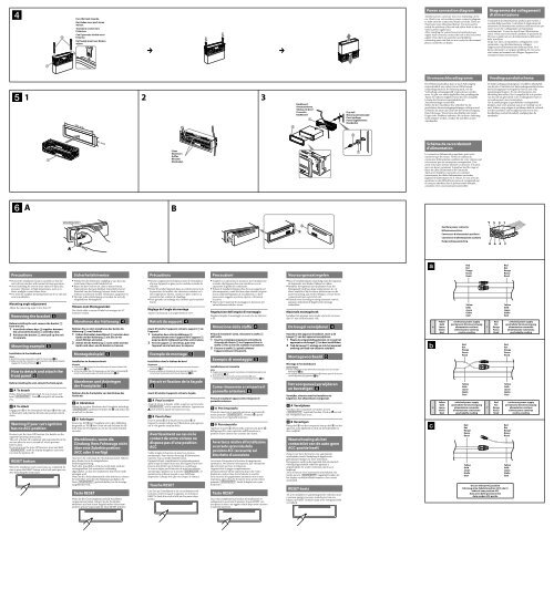
Mounting angle adjustment<br />
Adjust the mounting angle to less than 45°.<br />
Removing the bracket<br />
Before installing the unit, remove the bracket <br />
from the unit.<br />
1 Insert both release keys together between<br />
the unit and the bracket until they click.<br />
2 Pull down the bracket , then pull up the unit<br />
to separate.<br />
Mounting example<br />
Installation in the dashboard<br />
Notes<br />
Bend these claws outward for a tight fit, if necessary (-2).<br />
Make sure that the 4 catches on the protection collar are properly<br />
engaged in the slots of the unit (-3).<br />
How to detach and attach the<br />
front panel<br />
Before installing the unit, detach the front panel.<br />
-A To detach<br />
Before detaching the front panel, be sure to press and<br />
hold . Press , and pull it off towards<br />
you.<br />
-B To attach<br />
Engage part of the front panel with part of the unit,<br />
as illustrated, and push the left side into position until it<br />
clicks.<br />
Warning if your car’s ignition<br />
has no ACC position<br />
Be sure to set the Auto Off function. For details, see the<br />
supplied Operating Instructions.<br />
The unit will shut off completely and automatically in the<br />
set time after the unit is turned off, which prevents<br />
battery drain.<br />
If you do not set the Auto Off function, press and hold<br />
until the display disappears each time<br />
you turn the ignition off.<br />
RESET button<br />
When the installation and connections are completed, be<br />
sure to press the RESET button with a ball-point pen, etc.,<br />
after detaching the front panel.<br />
Wählen Sie den Einbauort sorgfältig so aus, dass das<br />
Gerät beim Fahren nicht hinderlich ist.<br />
Bauen Sie das Gerät so ein, dass es keinen hohen<br />
Temperaturen (keinem direkten Sonnenlicht, keiner<br />
Warmluft von der Heizung), keinem Staub, keinem<br />
Schmutz und keinen starken Vibrationen ausgesetzt ist.<br />
Für eine sichere Befestigung verwenden Sie stets die<br />
mitgelieferten Montageteile.<br />
Hinweis zum Montagewinkel<br />
Das Gerät sollte in einem Winkel von weniger als 45°<br />
montiert werden.<br />
Abnehmen der Halterung<br />
Nehmen Sie vor dem Installieren des Geräts die<br />
Halterung vom Gerät ab.<br />
1 Führen Sie beide Löseschlüssel zwischen dem<br />
Gerät und der Halterung ein, bis sie mit<br />
einem Klicken einrasten.<br />
2 Ziehen Sie die Halterung nach unten und das<br />
Gerät nach oben, um die beiden zu trennen.<br />
Montagebeispiel<br />
Installation im Armaturenbrett<br />
Hinweise<br />
Falls erforderlich, biegen Sie diese Klammern für einen sicheren Halt<br />
nach außen (-2).<br />
Achten Sie darauf, die 4 Verriegelungen an der Schutzumrandung <br />
korrekt in die Aussparungen am Gerät einzusetzen (-3).<br />
Abnehmen und Anbringen<br />
der Frontplatte<br />
Nehmen Sie die Frontplatte vor dem Einbau des<br />
Geräts ab.<br />
-A Abnehmen<br />
Halten Sie vor dem Abnehmen der Frontplatte unbedingt<br />
gedrückt. Drücken Sie und ziehen Sie<br />
sie auf sich zu heraus.<br />
-B Anbringen<br />
Setzen Sie Teil der Frontplatte wie in der Abbildung<br />
dargestellt an Teil des Geräts an und drücken Sie die<br />
linke Seite der Frontplatte an, bis sie mit einem Klicken<br />
einrastet.<br />
Warnhinweis, wenn die<br />
Zündung Ihres Fahrzeugs nicht<br />
über eine Zubehörposition<br />
(ACC oder I) verfügt<br />
Aktivieren Sie unbedingt die Abschaltautomatik. Näheres<br />
dazu finden Sie in der mitgelieferten<br />
Bedienungsanleitung.<br />
Nach dem Ausschalten wird das Gerät dann nach der<br />
voreingestellten Zeit automatisch vollständig<br />
abgeschaltet, so dass der Autobatterie kein Strom mehr<br />
entzogen wird.<br />
Wenn Sie die Abschaltautomatik nicht aktivieren, müssen<br />
Sie jedes Mal, wenn Sie die Zündung ausschalten, die<br />
Taste gedrückt halten, bis die Anzeige<br />
ausgeblendet wird.<br />
Taste RESET<br />
Wenn Sie das Gerät eingebaut und alle Anschlüsse<br />
vorgenommen haben, müssen Sie die Frontplatte<br />
abnehmen und mit einem Kugelschreiber oder einem<br />
anderen spitzen Gegenstand die Taste RESET drücken.<br />
Choisir soigneusement l’emplacement de l’installation<br />
afin que l’appareil ne gêne pas la conduite normale du<br />
véhicule.<br />
Eviter d’installer l’appareil dans un endroit exposé à de<br />
la poussière, de la saleté, des vibrations violentes ou à<br />
des températures élevées, comme en plein soleil ou à<br />
proximité d’un conduit de chauffage.<br />
Pour garantir un montage sûr, n’utiliser que le matériel<br />
fourni.<br />
Réglage de l’angle de montage<br />
Ajuster l’inclinaison à un angle inférieur à 45°.<br />
Retrait du support<br />
Avant d’installer l’appareil, retirez le support de<br />
l’appareil.<br />
1 Insérez les deux clés de déblocage <br />
simultanément entre l’appareil et le support <br />
jusqu’au déclic indiquant qu’elles sont en place.<br />
2 Tirez le support vers le bas, puis tirez<br />
l’appareil vers le haut pour les séparer.<br />
Exemple de montage<br />
Installation dans le tableau de bord<br />
Remarques<br />
Pliez ces griffes vers l’extérieur pour assurer une prise correcte si<br />
nécessaire (-2).<br />
Assurez-vous que les 4 loquets du tour de protection sont<br />
correctement insérés dans les fentes de l’appareil (-3).<br />
Retrait et fixation de la façade<br />
Avant d’installer l’appareil, retirez la façade.<br />
-A Pour la retirer<br />
Avant de retirer la façade, veillez à appuyer sur la touche<br />
et à la maintenir enfoncée. Appuyez sur<br />
, puis sortez la façade en tirant vers vous.<br />
-B Pour la fixer<br />
Fixez la partie de la façade sur la partie de<br />
l’appareil, comme indiqué sur l’illustration, puis appuyez<br />
sur le côté gauche jusqu’au déclic.<br />
Avertissement au cas où le<br />
contact de votre voiture ne<br />
dispose pas d’une position<br />
ACC<br />
Veillez à régler la fonction de mise hors tension<br />
automatique. Pour obtenir davantage d’informations,<br />
reportez-vous au mode d’emploi fourni.<br />
L’appareil s’éteint complètement et automatiquement<br />
après le laps de temps choisi une fois l’appareil mis hors<br />
tension afin d’éviter que la batterie ne se décharge.<br />
Si vous ne réglez pas la fonction de mise hors tension<br />
automatique, appuyez sur la touche et<br />
maintenez-la enfoncée jusqu’à ce que l’affichage<br />
disparaisse à chaque fois que vous coupez le contact.<br />
Touche RESET<br />
Une fois que l’installation et les raccordements sont<br />
terminés, retirez la façade et appuyez sur le bouton<br />
RESET à l’aide d’un stylo à bille ou d’un autre objet<br />
pointu.<br />
Scegliere con attenzione la posizione per l’installazione<br />
in modo che l’apparecchio non interferisca con le<br />
operazioni di guida del conducente.<br />
Evitare di installare l’apparecchio dove sia soggetto ad<br />
alte temperature, come alla luce solare diretta o al getto<br />
di aria calda dell’impianto di riscaldamento, o dove<br />
possa essere soggetto a polvere, sporco e vibrazioni<br />
eccessive.<br />
Usare solo il materiale di montaggio in dotazione per<br />
un’installazione stabile e sicura.<br />
Regolazione dell’angolo di montaggio<br />
Regolare l’angolo di montaggio in modo che sia inferiore<br />
a 45°.<br />
Rimozione della staffa<br />
Prima di installare l’unità, rimuovere la staffa <br />
dall’unità.<br />
1 Inserire contemporaneamente entrambe le<br />
chiavette di rilascio tra l’apparecchio e la<br />
staffa fino a che non scattano in posizione.<br />
2 Estrarre la staffa , quindi sollevare<br />
l’apparecchio per rimuoverlo.<br />
Esempio di montaggio<br />
Installazione nel cruscotto<br />
Note<br />
Piegare verso l’esterno questi morsetti per un’installazione più sicura,<br />
se necessario (-2).<br />
Assicurarsi che i 4 fermi sulla cornice protettiva siano<br />
correttamente inseriti negli alloggiamenti dell’apparecchio (-3).<br />
Come rimuovere e reinserire il<br />
pannello anteriore<br />
Prima di installare l’apparecchio rimuovere il<br />
pannello anteriore.<br />
-A Per rimuoverlo<br />
Prima di rimuovere il pannello anteriore, assicurarsi di<br />
tenere premuto . Premere , quindi<br />
tirare verso di sé il pannello anteriore.<br />
-B Per reinserirlo<br />
Applicare la parte del pannello anteriore alla parte <br />
dell’apparecchio come mostrato nell’illustrazione e<br />
premere il lato sinistro fino a sentire uno scatto.<br />
Avvertenza relativa all’installazione<br />
su un’auto sprovvista della<br />
posizione ACC (accessoria) sul<br />
blocchetto di accensione<br />
Accertarsi di impostare la funzione di spegnimento<br />
automatico. Per ulteriori informazioni, fare riferimento<br />
alle istruzioni per l’uso in dotazione.<br />
L’apparecchio si spegne completamente e<br />
automaticamente all’ora impostata dopo che è stato<br />
disattivato, onde evitare che la batteria si scarichi.<br />
Se la funzione di spegnimento automatico non è stata<br />
impostata, ogni volta che il motore viene spento tenere<br />
premuto finché il display non viene<br />
disattivato.<br />
Tasto RESET<br />
Una volta completate le procedure di installazione e i<br />
collegamenti, accertarsi di premere il tasto RESET con<br />
una penna a sfera o un oggetto simile dopo avere rimosso<br />
il pannello anteriore.<br />
Kies de installatieplaats zorgvuldig zodat het apparaat<br />
de bestuurder niet hindert tijdens het rijden.<br />
Installeer het apparaat niet op plaatsen waar het<br />
blootgesteld wordt aan hoge temperaturen, b.v. in<br />
direct zonlicht of bij de warme luchtstroom van de<br />
autoverwarming, aan sterke trillingen, of waar het in<br />
contact komt met veel stof of vuil.<br />
Gebruik voor het veilig en stevig monteren van het<br />
apparaat uitsluitend de bijgeleverde montageonderdelen.<br />
Maximale montagehoek<br />
Installeer het apparaat nooit onder een hoek van meer<br />
dan 45° met het horizontale vlak.<br />
De beugel verwijderen<br />
Voordat u het apparaat installeert, moet u de<br />
beugel van het apparaat verwijderen.<br />
1 Plaats de ontgrendelingssleutels tussen het<br />
apparaat en de beugel tot deze vastklikken.<br />
2 Trek de beugel omlaag en trek het apparaat<br />
omhoog om deze van elkaar te scheiden.<br />
Montagevoorbeeld<br />
Montage in het dashboard<br />
Opmerkingen<br />
Indien nodig kunt u deze klemhaken ombuigen voor een steviger<br />
bevestiging (-2).<br />
De 4 grepen op de beschermende rand moeten goed in de sleuven<br />
van het apparaat zijn geplaatst (-3).<br />
Het voorpaneel verwijderen<br />
en bevestigen<br />
Verwijder, alvorens met het installeren te<br />
beginnen, het afneembare voorpaneel.<br />
-A Verwijderen<br />
Voordat u het voorpaneel verwijdert, moet u<br />
ingedrukt houden. Druk op<br />
het voorpaneel naar u toe.<br />
en trek<br />
-B Bevestigen<br />
Breng deel van het voorpaneel aan op deel van het<br />
apparaat zoals afgebeeld en druk op de linkerzijde tot<br />
deze vastklikt.<br />
Waarschuwing als het<br />
contactslot van de auto geen<br />
ACC-positie heeft<br />
Zorg ervoor dat u de functie voor automatisch<br />
uitschakelen instelt. Raadpleeg de bijgeleverde<br />
gebruiksaanwijzing voor meer informatie.<br />
Het apparaat wordt na de ingestelde tijd automatisch<br />
volledig uitgeschakeld nadat het apparaat is<br />
uitgeschakeld. Zo wordt voorkomen dat de accu<br />
leegloopt.<br />
Als u de functie voor automatisch uitschakelen niet<br />
instelt, moet u ingedrukt houden tot<br />
het display verdwijnt telkens wanneer u het contact<br />
uitschakelt.<br />
RESET-toets<br />
Als u de installatie en aansluitingen hebt voltooid, moet<br />
u met een puntig voorwerp, zoals de punt van een<br />
balpen, op RESET drukken nadat u het voorpaneel hebt<br />
verwijderd.<br />
4<br />
4<br />
Yellow<br />
Gelb<br />
Jaune<br />
Giallo<br />
Geel<br />
Yellow<br />
Gelb<br />
Jaune<br />
Giallo<br />
Geel<br />
Yellow<br />
Gelb<br />
Jaune<br />
Giallo<br />
Geel<br />
continuous power supply<br />
permanente Stromversorgung<br />
alimentation continue<br />
alimentazione continua<br />
continu voeding<br />
Red<br />
Rot<br />
Rouge<br />
Rosso<br />
Rood<br />
Yellow<br />
Gelb<br />
Jaune<br />
Giallo<br />
Geel<br />
switched power supply<br />
geschaltete Stromversorgung<br />
alimentation commutée<br />
alimentazione commutata<br />
geschakelde voeding<br />
Red<br />
Rot<br />
Rouge<br />
Rosso<br />
Rood<br />
Yellow<br />
Gelb<br />
Jaune<br />
Giallo<br />
Geel<br />
Yellow<br />
Gelb<br />
Jaune<br />
Giallo<br />
Geel<br />
Red<br />
Rot<br />
Rouge<br />
Rosso<br />
Rood<br />
Yellow<br />
Gelb<br />
Jaune<br />
Giallo<br />
Geel<br />
Red<br />
Rot<br />
Rouge<br />
Rosso<br />
Rood<br />
Yellow<br />
Gelb<br />
Jaune<br />
Giallo<br />
Geel<br />
the car without ACC position<br />
Fahrzeug ohne Zubehörposition (ACC oder I)<br />
Véhicule sans position ACC<br />
Auto priva della posizione ACC<br />
Auto zonder ACC-positie<br />
7<br />
7<br />
Red<br />
Rot<br />
Rouge<br />
Rosso<br />
Rood<br />
Red<br />
Rot<br />
Rouge<br />
Rosso<br />
Rood<br />
switched power supply<br />
geschaltete Stromversorgung<br />
alimentation commutée<br />
alimentazione commutata<br />
geschakelde voeding<br />
continuous power supply<br />
permanente Stromversorgung<br />
alimentation continue<br />
alimentazione continua<br />
continu voeding


