BEDIENUNGSANLEITUNG CL-66 Compressor-Limiter - Djpoint.net
BEDIENUNGSANLEITUNG CL-66 Compressor-Limiter - Djpoint.net
BEDIENUNGSANLEITUNG CL-66 Compressor-Limiter - Djpoint.net

You also want an ePaper? Increase the reach of your titles
YUMPU automatically turns print PDFs into web optimized ePapers that Google loves.
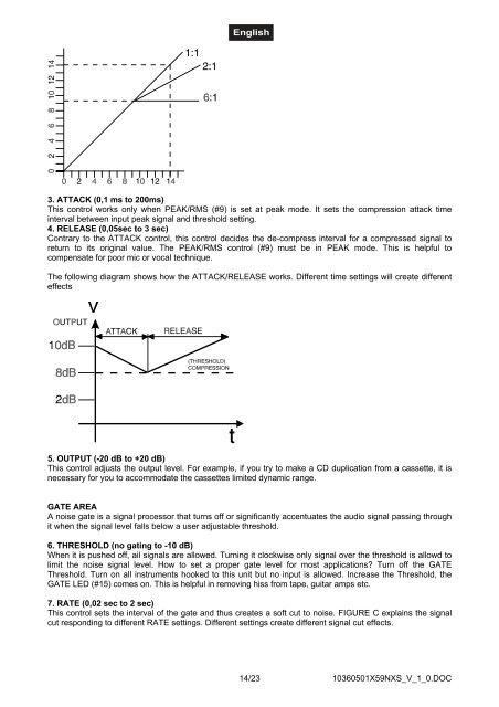
3. ATTACK (0,1 ms to 200ms)<br />
This control works only when PEAK/RMS (#9) is set at peak mode. It sets the compression attack time<br />
interval between input peak signal and threshold setting.<br />
4. RELEASE (0,05sec to 3 sec)<br />
Contrary to the ATTACK control, this control decides the de-compress interval for a compressed signal to<br />
return to its original value. The PEAK/RMS control (#9) must be in PEAK mode. This is helpful to<br />
compensate for poor mic or vocal technique.<br />
The following diagram shows how the ATTACK/RELEASE works. Different time settings will create different<br />
effects<br />
5. OUTPUT (-20 dB to +20 dB)<br />
This control adjusts the output level. For example, if you try to make a CD duplication from a cassette, it is<br />
necessary for you to accommodate the cassettes limited dynamic range.<br />
GATE AREA<br />
A noise gate is a signal processor that turns off or significantly accentuates the audio signal passing through<br />
it when the signal level falls below a user adjustable threshold.<br />
6. THRESHOLD (no gating to -10 dB)<br />
When it is pushed off, ail signals are allowed. Turning it clockwise only signal over the threshold is allowd to<br />
limit the noise signal level. How to set a proper gate level for most applications? Turn off the GATE<br />
Threshold. Turn on all instruments hooked to this unit but no input is allowed. Increase the Threshold, the<br />
GATE LED (#15) comes on. This is helpful in removing hiss from tape, guitar amps etc.<br />
7. RATE (0,02 sec to 2 sec)<br />
This control sets the interval of the gate and thus creates a soft cut to noise. FIGURE C explains the signal<br />
cut responding to different RATE settings. Different settings create different signal cut effects.<br />
14/23<br />
10360501X59NXS_V_1_0.DOC