

5 - markhip
5 - markhip
5 - markhip

Create successful ePaper yourself
Turn your PDF publications into a flip-book with our unique Google optimized e-Paper software.
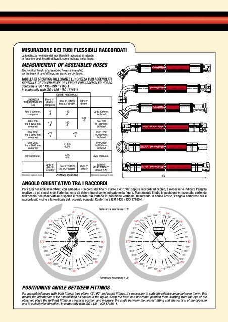
MISURAZIONE DEI TUBI FLESSIBILI RACCORDATI<br />
La lunghezza nominale dei tubi flessibili raccordati si intende,<br />
in funzione degli inserti utilizzati, come indicato nella figura:<br />
MEASUREMENT OF ASSEMBLED HOSES<br />
The nominal lenght of assembled hoses is intended,<br />
on the base of used fittings, as stated on de figure:<br />
TABELLA DI SPECIFICA TOLLERANZE LUNGHEZZA TUBI ASSEMBLATI<br />
SCHEDULE OF TOLERANCES OF LENGHT FOR ASSEMBLED HOSES<br />
Conforme a ISO 1436 - ISO 17165-1<br />
In conformity with ISO 1436 - ISO 17165-1<br />
LUNGHEZZA<br />
TUBI ASSEMBLATI<br />
(LN)<br />
Fino a 630 mm.<br />
compreso<br />
Oltre 630<br />
fino a 1250 mm.<br />
compresi<br />
Oltre 1250<br />
fino a 2500 mm.<br />
compresi<br />
Oltre 2500<br />
fino a 8000 mm.<br />
compresi<br />
Oltre 8000 mm.<br />
Dimensioni espresse in mm.<br />
Fino a 1”<br />
(DN25)<br />
compreso<br />
+7<br />
-3<br />
+12<br />
-4<br />
+20<br />
-6<br />
Up to 1”<br />
(DN25)<br />
included<br />
DIAMETRI NOMINALI<br />
Oltre 1” (DN25)<br />
fino a 2” (DN50)<br />
+1,5%<br />
-0,5%<br />
+3%<br />
-1%<br />
Over 1” (DN25)<br />
up to 2” (DN50)<br />
NOMINAL DIAMETER<br />
Oltre 2”<br />
(DN50)<br />
Over 2”<br />
(DN50)<br />
Up to 630 mm.<br />
included<br />
Over 630<br />
to 1250 mm.<br />
included<br />
Over 1250<br />
to 2500 mm.<br />
included<br />
Over 2500<br />
to 8000 mm.<br />
included<br />
Over 8000 mm.<br />
LENGHT<br />
OF ASSEMBLED<br />
HOSES (LN)<br />
Dimensions expressed by mm.<br />
ANGOLO ORIENTATIVO TRA I RACCORDI<br />
+12<br />
-4<br />
+20<br />
-6<br />
Per i tubi flessibili assemblati con ambedue i raccordi del tipo di curve a 45°, 90° oppure raccordi ad occhio, è necessario indicare l’angolo<br />
relativo tra gli stessi, cioè l’orientamento da determinarsi come indicato nella figura. Mantenendo il tubo in posizione orrizzontale, partendo<br />
dall’occhio dell’osservatore disporre il raccordo più lontano in posizione verticale, misurando in senso orario, l’angolo compreso tra il<br />
raccordo più vicino e la verticale del raccordo opposto. Conforme a ISO 1436 - ISO 17165-1.<br />
340°<br />
330°<br />
315° 320°<br />
310°<br />
300°<br />
290°<br />
280°<br />
270°<br />
POSITIONING ANGLE BETWEEN FITTINGS<br />
+25<br />
-6<br />
0°<br />
350°<br />
+25<br />
-6<br />
15°<br />
10°<br />
20°<br />
30°<br />
40° 45°<br />
50°<br />
60°<br />
260°<br />
250°<br />
240°<br />
230°<br />
225°<br />
220°<br />
210°<br />
200°<br />
190° 170°<br />
180°<br />
160°150°140°135°<br />
100°<br />
110°<br />
120°<br />
130°<br />
Tolleranza ammessa ± 3°<br />
70°<br />
80°<br />
90°<br />
Permitted tolerance ± 3°<br />
For assembled hoses with both fittings type elbow 45°, 90° and banjo fittings, it’s necessary to state the relative angle between therm, this<br />
means the orientation to be estabilished as shown in the figure. Keep the hose in a horizontal position then, starting from the eye of the<br />
observer, place the furthest fitting in a vertical position and measure the angle between the nearest fitting and the vertical of the opposite<br />
one in a clockwise direction. In conformity with ISO 1436 - ISO 17165-1.<br />
270°<br />
300°<br />
240°<br />
LN<br />
0°<br />
10°<br />
330°<br />
315°<br />
45°<br />
15°<br />
340° 20°<br />
30°<br />
320°<br />
40°<br />
310°<br />
50°<br />
350°<br />
290°<br />
280°<br />
260°<br />
250°<br />
60°<br />
120°<br />
230°<br />
130°<br />
225°<br />
135°<br />
220°<br />
140°<br />
210°<br />
150°<br />
200°<br />
160°<br />
190° 170°<br />
180°<br />
70°<br />
80°<br />
90°<br />
100°<br />
110°