Amplificatore con valvole subminiatura - Le Radio di Sophie
Amplificatore con valvole subminiatura - Le Radio di Sophie
Amplificatore con valvole subminiatura - Le Radio di Sophie

Create successful ePaper yourself
Turn your PDF publications into a flip-book with our unique Google optimized e-Paper software.
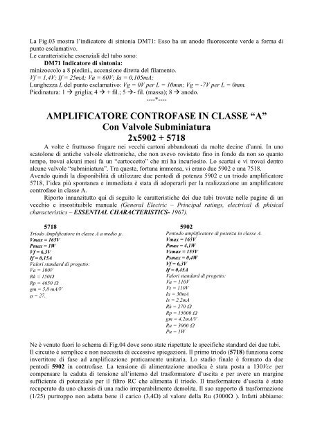
La Fig.03 mostra l’in<strong>di</strong>catore <strong>di</strong> sintonia DM71: Esso ha un anodo fluorescente verde a forma <strong>di</strong><br />
punto esclamativo.<br />
<strong>Le</strong> caratteristiche essenziali del tubo sono:<br />
DM71 In<strong>di</strong>catore <strong>di</strong> sintonia:<br />
minizoccolo a 8 pie<strong>di</strong>ni., accensione <strong>di</strong>retta del filamento.<br />
Vf = 1,4V; If = 25mA; Va = 60V; Ia = 0,105mA;<br />
Lunghezza L del punto esclamativo: Vg = 0V per L = 10mm; Vg = -7V per L = 0mm.<br />
Pie<strong>di</strong>natura: 1 griglia; 4 + fil.; 5 - fil. (massa); 8 anodo.<br />
----*----<br />
AMPLIFICATORE CONTROFASE IN CLASSE “A”<br />
Con Valvole Subminiatura<br />
2x5902 + 5718<br />
A volte è fruttuoso frugare nei vecchi cartoni abbandonati da molte decine d’anni. In uno<br />
scatolone <strong>di</strong> antiche <strong>valvole</strong> elettroniche, che non avevo rovistato fino in fondo da non so quanto<br />
tempo, trovai alcuni mesi fa un “cartoccetto” che mi ha incuriosito. Lo scartai e vi trovai dentro<br />
alcune <strong>valvole</strong> “<strong>subminiatura</strong>”. Tra queste, fortuna immensa, vi erano due 5902 e una 7518.<br />
Avendo quin<strong>di</strong> la <strong>di</strong>sponibilità <strong>di</strong> utilizzare due pento<strong>di</strong> <strong>di</strong> potenza 5902 e un triodo amplificatore<br />
5718, l’idea più spontanea e imme<strong>di</strong>ata è stata <strong>di</strong> adoperarli per la realizzazione un amplificatore<br />
<strong>con</strong>trofase in classe A.<br />
Riporto innanzitutto qui <strong>di</strong> seguito le caratteristiche dei due tubi trovate nelle pagine <strong>di</strong> un<br />
vecchio e insostituibile manuale (General Electric – Principal ratings, electrical & phisical<br />
characteristics – ESSENTIAL CHARACTERISTICS- 1967).<br />
5718<br />
Triodo <strong>Amplificatore</strong> in classe A a me<strong>di</strong>o µ .<br />
Vmax = 165V<br />
Pmax = 1W<br />
Vf = 6,3V<br />
If = 0,15A<br />
Valori standard <strong>di</strong> progetto:<br />
Va = 100V<br />
Rk = 150Ω<br />
Rp = 4650 Ω<br />
gm = 5,8 mA/V<br />
µ = 27.<br />
5902<br />
Pentodo amplificatore <strong>di</strong> potenza in classe A.<br />
Vmax = 165V<br />
Pmax = 4,1W<br />
Vsmax = 155V<br />
Psmax = 0,4W<br />
Vf = 6,3V<br />
If = 0,45A<br />
Valori standard <strong>di</strong> progetto:<br />
Va = 110V<br />
Vs = 110V<br />
Ia = 30mA<br />
Is = 2,2mA<br />
Rk = 270 Ω<br />
Rp = 15000 Ω<br />
gm = 4,2mA/V<br />
Ru = 3000 Ω<br />
Pu = 1W<br />
Ne è venuto fuori lo schema <strong>di</strong> Fig.04 dove sono state rispettate le specifiche standard dei due tubi.<br />
Il circuito è semplice e non necessita <strong>di</strong> eccessive spiegazioni. Il primo triodo (5718) funziona come<br />
invertitore <strong>di</strong> fase ad amplificazione praticamente unitaria. Lo sta<strong>di</strong>o finale è formato da due<br />
pento<strong>di</strong> 5902 in <strong>con</strong>trofase. La tensione <strong>di</strong> alimentazione ano<strong>di</strong>ca è stata posta a 130Vcc per<br />
compensare la caduta <strong>di</strong> tensione all’interno del trasformatore d’uscita e per avere un margine<br />
sufficiente <strong>di</strong> potenziale per il filtro RC che alimenta il triodo. Il trasformatore d’uscita è stato<br />
recuperato da uno chassis <strong>di</strong> una ra<strong>di</strong>o irreparabilmente demolita. Il suo rapporto <strong>di</strong> trasformazione<br />
(1/25) purtroppo non adatta bene il carico (3,4Ω) al valore della Ru (3000Ω ). Infatti abbiamo: