

Fase - PetSafe Australia
Fase - PetSafe Australia
Fase - PetSafe Australia

Create successful ePaper yourself
Turn your PDF publications into a flip-book with our unique Google optimized e-Paper software.
Step<br />
3<br />
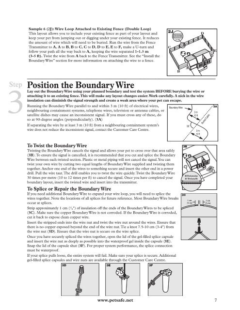
Sample 6 (2J): Wire Loop Attached to Existing Fence (Double Loop)<br />
This layout allows you to include your existing fence as part of your layout and<br />
keep your pet from jumping out or digging under your existing fence. It reduces<br />
the amount of wire which will need to be buried. Run the wire from the Fence<br />
Transmitter to A, A to B, B to C, C to D, D to E, E to F, make a U-turn and<br />
follow your path all the way back to A, keeping the wire separated 1-1.5 m<br />
(3-5 ft). Twist the wire from A back to the Fence Transmitter. See the “Install the<br />
Boundary Wire” section for more information on attaching the wire to a fence.<br />
__________________________________________________<br />
Position the Boundary Wire<br />
Lay out the Boundary Wire using your planned boundary and test the system BEFORE burying the wire or<br />
attaching it to an existing fence. This will make any layout changes easier. Work carefully. A nick in the wire<br />
insulation can diminish the signal strength and create a weak area where your pet can escape.<br />
Running the Boundary Wire parallel to and within 3 m (10 ft) of electrical wires,<br />
neighbouring containment systems, telephone wires, television or antenna cables, or<br />
satellite dishes may cause an inconsistent signal. If you must cross any of these, do<br />
so at 90-degree angles (perpendicularly). (3A)<br />
If separating the wire by at least 3 m (10 ft) from a neighbouring containment system’s<br />
wire does not reduce the inconsistent signal, contact the Customer Care Centre.<br />
www.petsafe.net 7<br />
C<br />
1-1.5 m<br />
(3-5 ft)<br />
B<br />
Boundary Wire<br />
To Twist the Boundary Wire<br />
Twisting the Boundary Wire cancels the signal and allows your pet to cross over that area safely<br />
(3B). To ensure the signal is cancelled, it is recommended that you cut and splice the Boundary<br />
Wire between each twisted section. Plastic or metal piping will not cancel the signal. You can<br />
twist your own wire by cutting two equal lengths of Boundary Wire supplied and twisting them<br />
together. Anchor one end of the wires to something secure and insert the other end in a power<br />
drill. Pull the wire taut. The drill enables you to twist the wire quickly. Twist the Boundary Wire<br />
30 times per metre (10 to 12 times per ft) to cancel the signal. Once you have completed your<br />
boundary layout, insert the twisted wire and insert into the transmitter.<br />
To Splice or Repair the Boundary Wire<br />
If you need additional Boundary Wire to expand your wire loop, you will need to splice the<br />
wires together. Note the locations of all splices for future reference. Most Boundary Wire breaks<br />
occur at splices.<br />
Strip approximately 1 cm ( 3 /8") of insulation off the ends of the Boundary Wires to be spliced<br />
(3C). Make sure the copper Boundary Wire is not corroded. If the Boundary Wire is corroded,<br />
cut it back to expose clean copper wire.<br />
Insert the stripped ends into the wire nut and twist the wire nut around the wires. Ensure that<br />
there is no copper exposed beyond the end of the wire nut. Tie a knot 7.5-10 cm (3-4") from<br />
the wire nut (3D). Ensure that the wire nut is secure on the wire splice.<br />
Once you have securely spliced the wires together, open the lid of the gel-fi lled splice capsule<br />
and insert the wire nut as deeply as possible into the waterproof gel inside the capsule (3E).<br />
Snap the lid of the capsule shut (3F). For proper system performance, the splice connection<br />
must be waterproof.<br />
If your splice pulls loose, the entire system will fail. Make sure your splice is secure. Additional<br />
gel-fi lled splice capsules and wire nuts are available through the Customer Care Centre.<br />
3D 3E 3F<br />
A<br />
90˚<br />
3 m<br />
10 ft<br />
3 m<br />
10 ft<br />
30 Twists/m<br />
10 Twists/ft<br />
1 cm<br />
( 3 /8 in)<br />
2<br />
1<br />
D<br />
Buried Cable<br />
1 cm<br />
( 3 /8 in)<br />
F<br />
E