Catalogo
Catalogo
Catalogo

You also want an ePaper? Increase the reach of your titles
YUMPU automatically turns print PDFs into web optimized ePapers that Google loves.
TECNOLOGIA<br />
TECHNOLOGY<br />
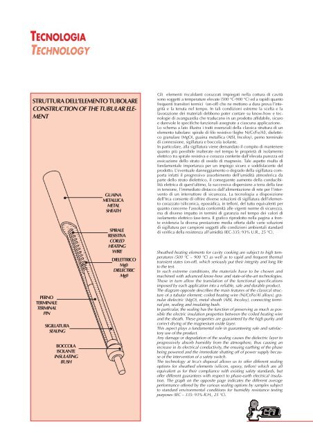
STRUTTURA DELL’ELEMENTO TUBOLARE<br />
CONSTRUCTION OF THE TUBULAR ELE-<br />
MENT<br />
PERNO<br />
TERMINALE<br />
TERMINAL<br />
PIN<br />
SIGILLATURA<br />
SEALING<br />
BOCCOLA<br />
ISOLANTE<br />
INSULATING<br />
BUSH<br />
GUAINA<br />
METALLICA<br />
METAL<br />
SHEATH<br />
SPIRALE<br />
RESISTIVA<br />
COILED<br />
HEATING<br />
WIRE<br />
DIELETTRICO<br />
Mg0<br />
DIELECTRIC<br />
Mg0<br />
Gli elementi riscaldanti corazzati impiegati nella cottura di cavità<br />
sono soggetti a temperature elevate (500 °C-900 °C) ed a rapidi quanto<br />
frequenti transitori termici (on-off) che ne mettono a dura prova l’integrità<br />
e la tenuta nel tempo. In tali condizioni estreme la scelta e la<br />
lavorazione dei materiali debbono poter contare su know-how e tecnologie<br />
di avanguardia che traducano in un prodotto affidabile, sicuro<br />
e durevole le specifiche funzionali assegnate a ciascuna applicazione.<br />
Lo schema a lato illustra i tratti essenziali della classica struttura di un<br />
elemento tubolare: spirale di filo resistivo (leghe Ni/Cr/Fe/Al), dielettrico<br />
granulare (MgO), guaina metallica (AISI, Incoloy), perno terminale<br />
di connessione, sigillatura e boccola isolante.<br />
In particolare, alla sigillatura viene demandato il compito di mantenere<br />
quanto più possibile inalterate nel tempo le proprietà di isolamento<br />
elettrico tra spirale resistiva e corazza conferite dall’elevata purezza ed<br />
essicazione dello strato di ossido di magnesio. Tale aspetto risulta di<br />
fondamentale importanza per un impiego sicuro e soddisfacente del<br />
prodotto. L’eventuale danneggiamento o degrado della sigillatura comporta<br />
infatti il progressivo assorbimento dell’umidità atmosferica da<br />
parte dello strato dielettrico, il conseguente aumento della conducibilità<br />
elettrica di quest’ultimo, la successiva dispersione a terra della fase<br />
in tensione, l’immediato distacco dall’alimentazione di rete per l’intervento<br />
di un interruttore di sicurezza. La tecnologia a disposizione<br />
dell’Irca consente di offrire diverse soluzioni di sigillatura dell’elemento<br />
corazzato (siliconica, epossidica, in teflon), del tutto equivalenti per<br />
quanto concerne l’assoluta conformità alle vigenti norme di sicurezza,<br />
ma di diverso impatto in termini di garanzia nel tempo dei valori di<br />
isolamento elettrico fase-terra. Il grafico riprodotto nella pagina a fronte<br />
evidenzia la diversa prestazione media offerta dalle varie soluzioni<br />
di sigillatura per campioni soggetti alle condizioni ambientali standard<br />
di verifica della resistenza all’umidità (IEC-335: 93% U.R., 25 °C).<br />
Sheathed heating elements for cavity cooking are subject to high temperatures<br />
(500 °C – 900 °C) as well as to rapid and frequent thermal<br />
transient states (on-off), which seriously put their integrity and long life<br />
to the test.<br />
In such extreme conditions, the materials have to be chosen and<br />
machined with advanced know-how and state-of-the-art technologies.<br />
These in turn allow the translation of the functional specifications<br />
imposed by each application into a reliable, safe and durable product.<br />
The diagram opposite describes the main features of the classical structure<br />
of a tubular element; coiled heating wire (Ni/Cr/Fe/Al alloys), granular<br />
dielectric (MgO), metal sheath (AISI, Incoloy), connecting terminal<br />
pin, sealing and insulating bush.<br />
In particular, the sealing has the function of preserving as much as possible<br />
the electric insulation properties between the coiled heating wire<br />
and the sheath. These properties are guaranteed by the high purity and<br />
correct drying of the magnesium oxide layer.<br />
This aspect plays a fundamental role in guaranteeing safe and satisfactory<br />
use of the product.<br />
Any damage or degradation of the sealing causes the dielectric layer to<br />
progressively absorb humidity from the atmosphere, thus causing an<br />
increase in its electrical conductivity, the ensuing earthing of the phase<br />
being powered and the immediate shutting off of power supply because<br />
of the intervention of a safety switch.<br />
The technology at Irca’s disposal allows us to offer different sealing<br />
options for sheathed elements (silicon, epoxy, teflon) which are all<br />
equivalent as for their compliance with existing safety standards, but<br />
offer different guarantees with respect to phase-earth electrical insulation.<br />
The graph on the opposite page indicates the different average<br />
performance offered by the various sealing options by samples subject<br />
to standard environmental conditions for humidity resistance testing<br />
purposes (IEC – 335: 93% R.H., 25 °C).