
You also want an ePaper? Increase the reach of your titles
YUMPU automatically turns print PDFs into web optimized ePapers that Google loves.
Esec_<strong>LRx</strong>MT_ITA+ING 13-12-2006 14:15 Pagina 26<br />
The Universal Sound<br />
I <strong>LRx</strong> 3.1MT Power Supply and output terminal description<br />
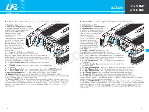
1_ Protection fuse: 80 A;<br />
2_ Anti-short circuit protective shield;<br />
3_ -Power (Ground): terminal block for the<br />
<strong>amplifier</strong> power supply negative pole<br />
connection. Insert the battery<br />
negative cable or a wire<br />
connected to the vehicle<br />
chassis here.<br />
The hole accepts cables up to<br />
2 A.W.G. For the best current<br />
transfer, we recommend<br />
the use of cables with as big<br />
a section as possible or, at<br />
least, with the same section<br />
as the wire connected to the<br />
positive pole;<br />
4_ + Power (11÷15 VDC): terminal block for<br />
the <strong>amplifier</strong> power supply positive pole connection.<br />
Insert the battery positive cable here. The hole accepts cables up<br />
to 2 A.W.G. For the best current transfer, we recommend the use of<br />
5<br />
cables with as big a section as possible or, at least, with the same section<br />
as the wire connected to the negative pole;<br />
5_ +/- Left A Speaker Out: + and - Left speaker power terminals of<br />
A channels;<br />
6_ +/- Right A Speaker Out: + and - Right speaker power terminals of<br />
A channels;<br />
7_ +/- Center Speaker Out: + and - speaker power terminals of the CENTER channel;<br />
8_ +/- Speaker SUB OUT: + and - speaker power terminals of the SUB output;<br />
9_ Remote Sub Volume: Inputs for sub volume remote control, optional VCRA;<br />
10_ Speaker ON: Inputs for turning on the <strong>amplifier</strong> through the speaker power cable.<br />
If source does not have a 12 VDC Remote output, connect any power output, even in parallel with<br />
a factory speaker, here for turning on the <strong>amplifier</strong>;<br />
11_ Remote IN/OUT: REM IN, terminal for the Remote cable coming from the device which turns<br />
on the <strong>amplifier</strong>. Voltage must be between 7 and 15 VDC. REM OUT, terminal for repeating Remote<br />
voltage and turning on other electronic devices. Output voltage is 12 VDC at 50 mA. Connection<br />
made to the SPK ON, also without the REM IN, will supply voltage to the REM OUT to turn on<br />
other devices.<br />
6<br />
9<br />
10<br />
11<br />
3<br />
1<br />
2<br />
4<br />
7<br />
8<br />
Owner’s manual<br />
I <strong>LRx</strong> <strong>5.1MT</strong> Power Supply and output terminal description<br />
1_ Protection fuse: 100 A;<br />
2_ Anti-short circuit protective shield;<br />
3_ -Power (Ground): terminal block for the<br />
<strong>amplifier</strong> power supply negative pole<br />
connection. Insert the battery negative<br />
cable or a wire connected to the<br />
vehicle chassis here.<br />
The hole accepts cables up to<br />
2 A.W.G. For the best current<br />
transfer, we recommend<br />
the use of cables with as big<br />
a section as possible or, at<br />
least, with the same section<br />
as the wire connected to the<br />
positive pole;<br />
4_ + Power (11÷15 VDC): terminal block for<br />
the <strong>amplifier</strong> power supply positive pole connection.<br />
Insert the battery positive cable here. The hole accepts cables<br />
up to 2 A.W.G. For the best current transfer, we recommend the use<br />
of cables with as big a section as possible or, at least, with the same<br />
section as the wire connected to the negative pole;<br />
5_ +/- Left A Speaker Out: + and - Left speaker power terminals of<br />
A channels;<br />
6_ +/- Center Speaker Out: + and - speaker power terminals of the<br />
CENTER channel;<br />
<strong>LRx</strong> 3.1MT<br />
<strong>LRx</strong> <strong>5.1MT</strong><br />
7_ +/- Right A Speaker Out: + and – Right speaker power terminals of A channels;<br />
8_ +/- Left B Speaker Out: + and - Left speaker power terminals of B channels;<br />
9_ +/- Right B Speaker Out: + and - Right speaker power terminals of B channels;<br />
10_ +/- Speaker SUB OUT: + and - speaker power terminals of the SUB output;<br />
11_ Remote Sub Volume: Inputs for sub volume remote control, optional VCRA;<br />
12_ Speaker ON: Inputs for turning on the <strong>amplifier</strong> through the speaker power cable.<br />
If source does not have a 12 VDC Remote output, connect any power output, even in parallel with<br />
a factory speaker, here for turning on the <strong>amplifier</strong>;<br />
13_ Remote IN/OUT: REM IN, terminal for the Remote cable coming from the device which turns<br />
on the <strong>amplifier</strong>. Voltage must be between 7 and 15 VDC. REM OUT, terminal for repeating Remote<br />
voltage and turning on other electronic devices. Output voltage is 12 VDC at 50 mA. Connection<br />
made to the SPK ON, also without the REM IN, will supply voltage to the REM OUT to turn on<br />
other devices.<br />
130.com.ua<br />
50 51<br />
Autogood products internet store http://130.com.ua<br />
5 6<br />
7<br />
11<br />
12<br />
13<br />
3<br />
1<br />
2<br />
4<br />
8 9<br />
10