Caldaia Bongioanni Linea 28 CSI - Certened
Caldaia Bongioanni Linea 28 CSI - Certened
Caldaia Bongioanni Linea 28 CSI - Certened

Create successful ePaper yourself
Turn your PDF publications into a flip-book with our unique Google optimized e-Paper software.
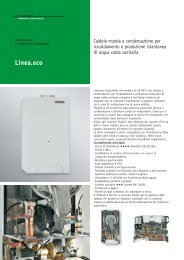
<strong>Caldaia</strong> murale a gas<br />
5196<br />
LINEA <strong>28</strong> <strong>CSI</strong><br />
Istruzioni per l’installazione,<br />
l’uso e la manutenzione
TABELLA DATI TECNICI:<br />
DATI GENERALITA’ CALDAIA<br />
CategoriaII2H3+<br />
Tipo combustibileMetano/GPL<br />
Portata termica nominale al focolare ................................................ kW/kcal/h .. 30,5/26.200<br />
Potenza termica utile nominale ......................................................... kW/kcal/h .. 27,4/23.600<br />
Potenza termica utile ridotta ............................................................. kW/kcal/h .... 10,0/8.600<br />
Accensioneionizzazione<br />
DATI COMBUSTIONE / GAS<br />
Consumo a potenza nominale - Metano G20 - (15 °C, 1013 mbar) ..... m 3 /h ..................... 3,2<br />
Consumo a potenza nominale - GPL - (G30 / G31) ............................. Kg/h .......... 2,41/2,37<br />
Pressione dinamica gas in ingresso - Metano G20 .............................. mbar ...................... 20<br />
Pressione dinamica gas in ingresso - Metano GPL (G30/G31) ........... mbar ................ 30/37<br />
Pressione bruciatore Metano G20 ........................................................ mbar ................... 15,0<br />
Pressione bruciatore Metano GPL (G30/G31) ..................................... mbar .......... <strong>28</strong>,8/36,7<br />
Ugelli bruciatore Metano G20 ................................................................ mm .................... 1,20<br />
Ugelli bruciatore Metano GPL (G30/G31) ............................................. mm .................... 0,68<br />
Attacco gas ............................................................................................... " ........................ 3/4<br />
DATI IDRAULICI - LATO IMPIANTO RISCALDAMENTO<br />
Temperatura minima in mandata ............................................................ °C ........................ 45<br />
Temperatura massima in mandata .......................................................... °C ........................ 85<br />
Capacita del vaso d’espansione ............................................................... l ............................ 7<br />
Pressione di precarica del vaso d’espansione ...................................... bar ......................... 1<br />
Pressione minima di impianto ............................................................... bar ...................... 0,6<br />
Pressione massima di esercizio ............................................................ bar ......................... 3<br />
Diametro attacchi mandata/ritorno impianto ............................................ " ........................ 3/4<br />
Valvola sicurezza primario, diametro attacco e pressione di taratura .............. " - bar .............. 3/4 - 3<br />
DATI PRODUZIONE A.C.S.<br />
Massima pressione acqua sanitaria ...................................................... bar ......................... 6<br />
Minima pressione d’esercizio ................................................................ bar ......................... 1<br />
Campo di regolazione temoeratura sanitario ......................................... °C .................. 40/60<br />
Diametro attacchi andata/ritorno sanitari .................................................. " ........................ 1/2<br />
Produzione acqua calda sanitaria (dT = 30 °C) ................................... l/min ................... 13,1<br />
Produzione acqua calda sanitaria (dT = 35 °C) ................................... l/min ................... 11,3<br />
Portata minima sanitari .......................................................................... l/min ........................ 2<br />
DATI DIMENSIONALI<br />
Diametro uscita fumi .............................................................................. mm .... 60/100, 80/80<br />
Misure ingombro (A×L×P) .................................................................... mm .. 800×450×355<br />
DATI ELETTRICI<br />
Alimentazione elettrica .......................................................................... V/Hz .............. 230/50<br />
Corrente ................................................................................................... A ........................ 0,8<br />
Potenza elettrica assorbita totale ............................................................ W ...................... 160<br />
Grado di protezione ................................................................................ IP ........................ 44<br />
LINEA <strong>28</strong> <strong>CSI</strong><br />
9
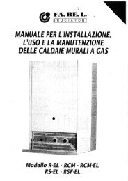
Schema idraulico<br />
1 – Pressostato aria 13 – Ingresso gas<br />
2 – Ventilatore 14 – Sonda temperatura sanitario<br />
3 – Camera di combustione 15 – Uscita acqua calda sanitario<br />
4 – Scambiatore primario 16 – By pass automatico<br />
5 – Bruciatore 17 – Mandata impianto<br />
6 – Valvola gas 18 – Scarico caldaia<br />
7 – Vaso espansione 19 – Sensore pressione impianto<br />
8 – Circolatore 20 – Valvola tre vie<br />
9 – Flussostato sanitario 21 – Attuatore valvola tre vie<br />
10 – Valvola di sicurezza 22 – Scambiatore sanitario<br />
11 – Ritorno impianto 23 – Sonda temperatura riscaldamento<br />
12 – Ingresso acqua fredda sanitario 24 – Termostato di sicurezza<br />
10 LINEA <strong>28</strong> <strong>CSI</strong>