Terminali Idronici
Terminali Idronici
Terminali Idronici

Create successful ePaper yourself
Turn your PDF publications into a flip-book with our unique Google optimized e-Paper software.
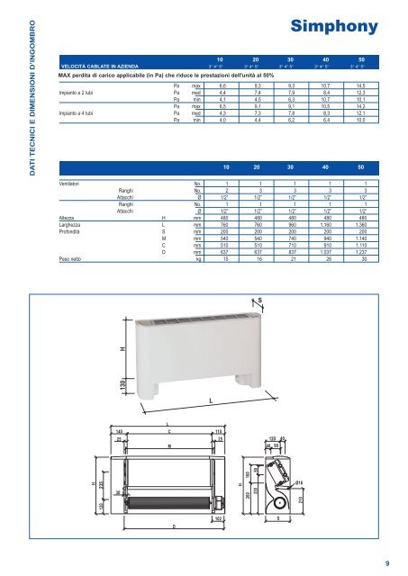
DATI TECNICI E DIMENSIONI D’INGOMBRO10 20 30 40 50VELOCITÀ CABLATE IN AZIENDA 3° 4° 5° 3° 4° 5° 3° 4° 5° 3° 4° 5° 3° 4° 5°MAX perdita di carico applicabile (in Pa) che riduce le prestazioni dell'unità al 50%SimphonyPa max 6,6 9,3 9,3 10,7 14,5Impianto a 2 tubi Pa med 4,4 7,4 7,9 8,4 12,3Pa min 4,1 4,5 6,3 10,7 10,1Pa max 6,5 9,1 9,1 10,5 14,2Impianto a 4 tubi Pa med 4,3 7,3 7,8 8,3 12,1Pa min 4,0 4,4 6,2 6,4 10,010 20 30 40 50Ventilatori No. 1 1 1 1 1Ranghi No. 2 3 3 3 3Attacchi Ø 1/2” 1/2” 1/2” 1/2” 1/2”Ranghi No. 1 1 1 1 1Attacchi Ø 1/2” 1/2” 1/2” 1/2” 1/2”Altezza H mm 480 480 480 480 480Larghezza L mm 760 760 960 1.160 1.360Profondità S mm 200 200 200 200 200M mm 540 540 740 940 1.140C mm 510 510 710 910 1.110D mm 637 637 837 1.037 1.237Peso netto kg 15 16 21 26 30S130HL140LC 11025 25M120 4040 90H23530120H2 60 16 03 30 8 0Ø16210D102S9