

Sony DSX-A60BT - DSX-A60BT Guida di installazione Francese
Sony DSX-A60BT - DSX-A60BT Guida di installazione Francese
Sony DSX-A60BT - DSX-A60BT Guida di installazione Francese

Create successful ePaper yourself
Turn your PDF publications into a flip-book with our unique Google optimized e-Paper software.
1 2<br />
1 2<br />
3 A B<br />
<br />
<br />
<br />
<br />
<br />
Face the hook inwards.<br />
Der Haken muss nach innen weisen.<br />
Tournez le crochet vers l’intérieur.<br />
Con il gancetto rivolto verso l’interno.<br />
Het haakje moet naar binnen wijzen.<br />
<br />
<br />
182 mm (7 1 /4 in)<br />
Catch<br />
Verriegelung<br />
Loquet<br />
Fermo<br />
Greep<br />
53 mm (2 1 /8 in)<br />
Claws<br />
Klammern<br />
Griffes<br />
Morsetti<br />
Klemhaken<br />
<br />
Dashboard<br />
Armaturenbrett<br />
Tableau de bord<br />
Cruscotto<br />
Dashboard<br />
<br />
OFF<br />
<br />
1 2<br />
3<br />
Fuse (10 A)<br />
Sicherung (10 A)<br />
Fusible (10 A)<br />
Fusibile (10 A)<br />
Zekering (10 A)<br />
Auxiliary power connector<br />
Hilfsstromanschluss<br />
Connecteur d’alimentation auxiliaire<br />
Connettore <strong>di</strong> alimentazione ausiliaria<br />
Hulpvoe<strong>di</strong>ngsaansluiting<br />
Red<br />
Rot<br />
Rouge<br />
Rosso<br />
Rood<br />
Yellow<br />
Gelb<br />
Jaune<br />
Giallo<br />
Geel<br />
Red<br />
Rot<br />
Rouge<br />
Rosso<br />
Rood<br />
Yellow<br />
Gelb<br />
Jaune<br />
Giallo<br />
Geel<br />
4<br />
7<br />
Yellow<br />
Gelb<br />
Jaune<br />
Giallo<br />
Geel<br />
Red<br />
Rot<br />
Rouge<br />
Rosso<br />
Rood<br />
continuous power supply<br />
permanente Stromversorgung<br />
alimentation continue<br />
alimentazione continua<br />
continue voe<strong>di</strong>ng<br />
switched power supply<br />
geschaltete Stromversorgung<br />
alimentation commutée<br />
alimentazione commutata<br />
geschakelde voe<strong>di</strong>ng<br />
Red<br />
Rot<br />
Rouge<br />
Rosso<br />
Rood<br />
Yellow<br />
Gelb<br />
Jaune<br />
Giallo<br />
Geel<br />
Red<br />
Rot<br />
Rouge<br />
Rosso<br />
Rood<br />
Yellow<br />
Gelb<br />
Jaune<br />
Giallo<br />
Geel<br />
4<br />
7<br />
Yellow<br />
Gelb<br />
Jaune<br />
Giallo<br />
Geel<br />
Red<br />
Rot<br />
Rouge<br />
Rosso<br />
Rood<br />
switched power supply<br />
geschaltete Stromversorgung<br />
alimentation commutée<br />
alimentazione commutata<br />
geschakelde voe<strong>di</strong>ng<br />
continuous power supply<br />
permanente Stromversorgung<br />
alimentation continue<br />
alimentazione continua<br />
continue voe<strong>di</strong>ng<br />
Red<br />
Rot<br />
Rouge<br />
Rosso<br />
Rood<br />
Yellow<br />
Gelb<br />
Jaune<br />
Giallo<br />
Geel<br />
Red<br />
Rot<br />
Rouge<br />
Rosso<br />
Rood<br />
Yellow<br />
Gelb<br />
Jaune<br />
Giallo<br />
Geel<br />
the car without ACC position<br />
Fahrzeug ohne Zubehörposition (ACC oder I)<br />
Véhicule sans position ACC<br />
Auto priva della posizione ACC<br />
Auto zonder ACC-positie<br />
English<br />
Precautions<br />
ˎˎChoose the installation location carefully so that the<br />
unit will not interfere with normal driving operations.<br />
ˎˎAvoid installing the unit in areas subject to dust, <strong>di</strong>rt,<br />
excessive vibration, or high temperature, such as in<br />
<strong>di</strong>rect sunlight or near heater ducts.<br />
ˎˎUse only the supplied mounting hardware for a safe<br />
and secure installation.<br />
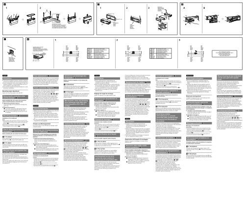
Mounting angle adjustment<br />
Adjust the mounting angle to less than 45°.<br />
Removing the protection collar<br />
and the bracket ( )<br />
Before installing the unit, remove the protection<br />
collar and the bracket from the unit.<br />
1 Remove the protection collar .<br />
Pinch both edges of the protection collar , then<br />
pull it out.<br />
2 Remove the bracket .<br />
Insert both release keys together between<br />
the unit and the bracket until they click.<br />
Pull down the bracket , then pull up the unit<br />
to separate.<br />
Mounting example ( )<br />
Installation in the dashboard<br />
Notes<br />
ˎˎBefore installing, make sure that the catches on both sides of the<br />
bracket are bent inwards 2 mm ( 3 /32 in). If the catches are straight<br />
or bent outwards, the unit will not be installed securely and may<br />
spring out (-1).<br />
ˎˎBend these claws outward for a tight fit, if necessary (-2).<br />
ˎˎMake sure that the 4 catches on the protection collar are<br />
properly engaged in the slots of the unit (-3).<br />
How to detach and attach the<br />
front panel ( )<br />
Before installing the unit, detach the front panel.<br />
-A To detach<br />
Before detaching the front panel, be sure to press and<br />
hold OFF. Press , and pull it off towards you.<br />
-B To attach<br />
Engage part of the front panel with part of the<br />
unit, as illustrated, and push the left side into position<br />
until it clicks.<br />
Warning if your car’s ignition has<br />
no ACC position<br />
Be sure to set the Auto Off function. For details, see<br />
the supplied Operating Instructions.<br />
The unit will shut off completely and automatically in<br />
the set time after the unit is turned off, which prevents<br />
battery drain.<br />
If you do not set the Auto Off function, press and hold<br />
OFF until the <strong>di</strong>splay <strong>di</strong>sappears each time you turn<br />
the ignition off.<br />
Fuse replacement ( )<br />
When replacing the fuse, be sure to use one matching<br />
the amperage rating stated on the original fuse. If the<br />
fuse blows, check the power connection and replace<br />
the fuse. If the fuse blows again after replacement,<br />
there may be an internal malfunction. In such a case,<br />
consult your nearest <strong>Sony</strong> dealer.<br />
Power connection <strong>di</strong>agram ( )<br />
Auxiliary power connector may vary depen<strong>di</strong>ng on the<br />
car. Check your car’s auxiliary power connector<br />
<strong>di</strong>agram to make sure the connections match<br />
correctly. There are three basic types (-1, -2, -3).<br />
You may need to switch the positions of the red and<br />
yellow leads in the car stereo’s power supply lead.<br />
After matching the connections and switched power<br />
supply leads correctly, connect the unit to the car’s<br />
power supply. If you have any questions and problems<br />
connecting your unit that are not covered in this<br />
manual, please consult the car dealer.<br />
Deutsch<br />
Sicherheitshinweise<br />
ˎˎWählen Sie den Einbauort sorgfältig so aus, dass das<br />
Gerät beim Fahren nicht hinderlich ist.<br />
ˎˎBauen Sie das Gerät so ein, dass es keinen hohen<br />
Temperaturen (keinem <strong>di</strong>rekten Sonnenlicht, keiner<br />
Warmluft von der Heizung), keinem Staub, keinem<br />
Schmutz und keinen starken Vibrationen ausgesetzt<br />
ist.<br />
ˎˎFür eine sichere Befestigung verwenden Sie stets <strong>di</strong>e<br />
mitgelieferten Montageteile.<br />
Hinweis zum Montagewinkel<br />
Das Gerät sollte in einem Winkel von weniger als 45°<br />
montiert werden.<br />
Abnehmen der Schutzumrandung<br />
und der Halterung ( )<br />
Nehmen Sie vor dem Installieren des Geräts <strong>di</strong>e<br />
Schutzumrandung und <strong>di</strong>e Halterung vom<br />
Gerät ab.<br />
1 Entfernen Sie <strong>di</strong>e Schutzumrandung .<br />
Fassen Sie <strong>di</strong>e Schutzumrandung mit den<br />
Fingern an den Seitenkanten und ziehen Sie sie<br />
heraus.<br />
2 Entfernen Sie <strong>di</strong>e Halterung .<br />
Führen Sie beide Löseschlüssel zwischen<br />
dem Gerät und der Halterung ein, bis sie mit<br />
einem Klicken einrasten.<br />
Ziehen Sie <strong>di</strong>e Halterung nach unten und das<br />
Gerät nach oben, um <strong>di</strong>e beiden zu trennen.<br />
Montagebeispiel ( )<br />
Installation im Armaturenbrett<br />
Hinweise<br />
ˎˎVergewissern Sie sich vor dem Installieren, dass <strong>di</strong>e Verriegelungen<br />
an beiden Seiten der Halterung um 2 mm nach innen gebogen<br />
sind. Wenn <strong>di</strong>e Verriegelungen gerade oder nach außen gebogen<br />
sind, lässt sich das Gerät nicht sicher installieren und kann<br />
herausspringen (-1).<br />
ˎˎFalls erforderlich, biegen Sie <strong>di</strong>ese Klammern für einen sicheren<br />
Halt nach außen (-2).<br />
ˎˎAchten Sie darauf, <strong>di</strong>e 4 Verriegelungen an der Schutzumrandung<br />
korrekt in <strong>di</strong>e Aussparungen am Gerät einzusetzen (-3).<br />
Abnehmen und Anbringen der<br />
Frontplatte ( )<br />
Nehmen Sie <strong>di</strong>e Frontplatte vor dem Einbau des<br />
Geräts ab.<br />
-A Abnehmen<br />
Halten Sie vor dem Abnehmen der Frontplatte<br />
unbe<strong>di</strong>ngt OFF gedrückt. Drücken Sie und ziehen<br />
Sie <strong>di</strong>e Frontplatte auf sich zu und heraus.<br />
-B Anbringen<br />
Setzen Sie Teil der Frontplatte wie in der Abbildung<br />
dargestellt an Teil des Geräts an und drücken Sie<br />
<strong>di</strong>e linke Seite der Frontplatte an, bis sie mit einem<br />
Klicken einrastet.<br />
Warnhinweis, wenn <strong>di</strong>e Zündung<br />
Ihres Fahrzeugs nicht über eine<br />
Zubehörposition (ACC oder I)<br />
verfügt<br />
Aktivieren Sie unbe<strong>di</strong>ngt <strong>di</strong>e Abschaltautomatik.<br />
Näheres dazu finden Sie in der mitgelieferten<br />
Be<strong>di</strong>enungsanleitung.<br />
Nach dem Ausschalten wird das Gerät dann nach der<br />
voreingestellten Zeit automatisch vollstän<strong>di</strong>g<br />
abgeschaltet, so dass der Autobatterie kein Strom<br />
mehr entzogen wird.<br />
Wenn Sie <strong>di</strong>e Abschaltautomatik nicht aktivieren,<br />
müssen Sie jedes Mal, wenn Sie <strong>di</strong>e Zündung<br />
ausschalten, <strong>di</strong>e Taste OFF gedrückt halten, bis <strong>di</strong>e<br />
Anzeige ausgeblendet wird.<br />
Austauschen der Sicherung ( )<br />
Wenn Sie eine Sicherung austauschen, achten Sie<br />
darauf, eine Ersatzsicherung mit dem gleichen<br />
Ampere-Wert wie <strong>di</strong>e Originalsicherung zu<br />
verwenden. Dieser ist auf der Originalsicherung<br />
angegeben. Wenn <strong>di</strong>e Sicherung durchbrennt,<br />
überprüfen Sie den Stromanschluss und tauschen <strong>di</strong>e<br />
Sicherung aus. Brennt <strong>di</strong>e neue Sicherung ebenfalls<br />
durch, kann eine interne Fehlfunktion vorliegen.<br />
Wenden Sie sich in einem solchen Fall an Ihren<br />
<strong>Sony</strong>-Händler.<br />
Stromanschluss<strong>di</strong>agramm ( )<br />
Der Hilfsstromanschluss kann je nach Fahrzeugtyp<br />
unterschiedlich sein. Sehen Sie im Hilfsstromanschluss<strong>di</strong>agramm<br />
für Ihr Fahrzeug nach, wie <strong>di</strong>e<br />
Verbindung ordnungsgemäß vorgenommen werden<br />
muss. Es gibt drei grundlegende Typen (-1, -2,<br />
-3). Sie müssen möglicherweise <strong>di</strong>e rote und gelbe<br />
Leitung des Stromversorgungskabels der<br />
Autostereoanlage vertauschen.<br />
Stellen Sie <strong>di</strong>e Anschlüsse her, schließen Sie <strong>di</strong>e<br />
geschalteten Stromversorgungsleitungen richtig an<br />
und verbinden Sie dann das Gerät mit der<br />
Stromversorgung Ihres Fahrzeugs. Wenn beim<br />
Anschließen des Geräts Fragen oder Probleme<br />
auftreten, <strong>di</strong>e in <strong>di</strong>eser Anleitung nicht erläutert<br />
werden, wenden Sie sich bitte an den Autohändler.<br />
Français<br />
Précautions<br />
ˎˎChoisir soigneusement l’emplacement de<br />
l’installation afin que l’appareil ne gêne pas la<br />
conduite normale du véhicule.<br />
ˎˎEviter d’installer l’appareil dans un endroit exposé à<br />
de la poussière, de la saleté, des vibrations violentes<br />
ou à des températures élevées, comme en plein<br />
soleil ou à proximité d’un conduit de chauffage.<br />
ˎˎPour garantir un montage sûr, n’utiliser que le<br />
matériel fourni.<br />
Réglage de l’angle de montage<br />
Ajuster l’inclinaison à un angle inférieur à 45°.<br />
Retrait du tour de protection et<br />
du support ( )<br />
Avant d’installer l’appareil, retirez le tour de<br />
protection et le support de l’appareil.<br />
1 Retirez le tour de protection .<br />
Saisissez les deux bords du tour de protection ,<br />
puis tirez pour l'extraire.<br />
2 Retirez le support .<br />
Insérez les deux clés de déblocage <br />
simultanément entre l’appareil et le support <br />
jusqu’au déclic in<strong>di</strong>quant qu’elles sont en place.<br />
Tirez le support vers le bas, puis tirez<br />
l’appareil vers le haut pour les séparer.<br />
Exemple de montage ( )<br />
Installation dans le tableau de bord<br />
Remarques<br />
ˎˎAvant l’installation, assurez-vous que les loquets des deux côtés du<br />
support sont bien pliés de 2 mm vers l’intérieur. Si les loquets<br />
sont droits ou pliés vers l’extérieur, l’appareil ne peut pas être fixé<br />
solidement et peut se détacher (-1).<br />
ˎˎPliez ces griffes vers l’extérieur pour assurer une prise correcte si<br />
nécessaire (-2).<br />
ˎˎAssurez-vous que les 4 loquets du tour de protection sont<br />
correctement insérés dans les fentes de l’appareil (-3).<br />
Retrait et fixation de la façade<br />
( )<br />
Avant d’installer l’appareil, retirez la façade.<br />
-A Pour la retirer<br />
Avant de retirer la façade, veillez à appuyer sur la<br />
touche OFF et à la maintenir enfoncée. Appuyez sur<br />
et détachez-la en la tirant vers vous.<br />
-B Pour la fixer<br />
Fixez la partie de la façade sur la partie de<br />
l’appareil, comme in<strong>di</strong>qué sur l’illustration, puis<br />
appuyez sur le côté gauche jusqu’au déclic.<br />
Avertissement au cas où le<br />
contact de votre voiture ne<br />
<strong>di</strong>spose pas d’une position ACC<br />
Veillez à régler la fonction de mise hors tension<br />
automatique. Pour obtenir davantage d’informations,<br />
reportez-vous au mode d’emploi fourni.<br />
L’appareil s’éteint complètement et automatiquement<br />
après le laps de temps choisi une fois qu’il a été mis<br />
hors tension afin d’éviter que la batterie ne se<br />
décharge.<br />
Si vous ne réglez pas la fonction de mise hors tension<br />
automatique, appuyez sur la touche OFF et<br />
maintenez-la enfoncée jusqu’à ce que l’affichage<br />
<strong>di</strong>sparaisse à chaque fois que vous coupez le contact.<br />
Remplacement du fusible ( )<br />
Lorsque vous remplacez le fusible, veillez à utiliser un<br />
fusible dont l’intensité, en ampères, correspond à la<br />
valeur in<strong>di</strong>quée sur le fusible usagé. Si le fusible saute,<br />
vérifiez le branchement de l’alimentation et<br />
remplacez-le. Si le nouveau fusible saute également, il<br />
est possible que l’appareil soit défectueux. Dans ce<br />
cas, consultez votre revendeur <strong>Sony</strong> le plus proche.<br />
Schéma de raccordement<br />
d’alimentation ( )<br />
Le connecteur d’alimentation auxiliaire peut varier<br />
suivant le type de voiture. Vérifiez le schéma du<br />
connecteur d’alimentation auxiliaire de votre voiture<br />
pour vous assurer que les connexions correspondent.<br />
Il en existe trois types de base (-1, -2, -3). Il se<br />
peut que vous deviez commuter la position des fils<br />
rouge et jaune du câble d’alimentation de l’autora<strong>di</strong>o.<br />
Après avoir établi les connexions et commuté<br />
correctement les câbles d’alimentation, raccordez<br />
l’appareil à l’alimentation de la voiture. Si vous avez<br />
des questions ou des <strong>di</strong>fficultés à propos de cet<br />
appareil qui ne sont pas abordées dans le présent<br />
mode d’emploi, consultez votre concessionnaire<br />
automobile.<br />
Italiano<br />
Precauzioni<br />
ˎˎScegliere con attenzione la posizione per<br />
l’<strong>installazione</strong> in modo che l’apparecchio non<br />
interferisca con le operazioni <strong>di</strong> guida del<br />
conducente.<br />
ˎˎEvitare <strong>di</strong> installare l’apparecchio dove sia soggetto<br />
ad alte temperature, come alla luce solare <strong>di</strong>retta o<br />
al getto <strong>di</strong> aria calda dell’impianto <strong>di</strong> riscaldamento,<br />
o dove possa essere soggetto a polvere, sporco e<br />
vibrazioni eccessive.<br />
ˎˎUsare solo il materiale <strong>di</strong> montaggio in dotazione<br />
per un’<strong>installazione</strong> stabile e sicura.<br />
Regolazione dell’angolo <strong>di</strong> montaggio<br />
Regolare l’angolo <strong>di</strong> montaggio in modo che sia<br />
inferiore a 45°.<br />
Rimozione della staffa e della<br />
cornice protettiva ( )<br />
Prima <strong>di</strong> installare l’apparecchio, rimuovere la<br />
cornice protettiva e la staffa dall’apparecchio.<br />
1 Rimuovere la cornice protettiva .<br />
Afferrare la cornice <strong>di</strong> protezione dai bor<strong>di</strong><br />
laterali, quin<strong>di</strong> estrarla.<br />
2 Rimuovere la staffa .<br />
Inserire contemporaneamente entrambe le<br />
chiavette <strong>di</strong> rilascio tra l’apparecchio e la<br />
staffa fino a che non scattano in posizione.<br />
Estrarre la staffa , quin<strong>di</strong> sollevare<br />
l’apparecchio per rimuoverlo.<br />
Esempio <strong>di</strong> montaggio ( )<br />
Installazione nel cruscotto<br />
Note<br />
ˎˎPrima <strong>di</strong> installare l’unità, accertarsi <strong>di</strong> ripiegare i fermi presenti su<br />
entrambi i lati della staffa verso l’interno <strong>di</strong> 2 mm. Se i fermi sono<br />
<strong>di</strong>ritti o ripiegati verso l’esterno, l’apparecchio non verrà installato in<br />
modo sicuro e potrebbe fuoriuscire (-1).<br />
ˎˎPiegare verso l’esterno questi morsetti per un’<strong>installazione</strong> più<br />
sicura, se necessario (-2).<br />
ˎˎAssicurarsi che i 4 fermi sulla cornice protettiva siano<br />
correttamente inseriti negli alloggiamenti dell’apparecchio (-3).<br />
Come rimuovere e reinserire il<br />
pannello anteriore ( )<br />
Prima <strong>di</strong> installare l’apparecchio rimuovere il<br />
pannello anteriore.<br />
-A Per rimuoverlo<br />
Prima <strong>di</strong> rimuovere il pannello anteriore, assicurarsi <strong>di</strong><br />
tenere premuto OFF. Premere , quin<strong>di</strong> tirare il<br />
pannello verso <strong>di</strong> sé.<br />
-B Per reinserirlo<br />
Applicare la parte del pannello anteriore alla parte<br />
dell’apparecchio come mostrato nell’illustrazione e<br />
premere il lato sinistro fino a sentire uno scatto.<br />
Avvertenza relativa<br />
all’<strong>installazione</strong> su un’auto<br />
sprovvista della posizione ACC<br />
(accessoria) sul blocchetto <strong>di</strong><br />
accensione<br />
Accertarsi <strong>di</strong> impostare la funzione <strong>di</strong> spegnimento<br />
automatico. Per ulteriori informazioni, fare riferimento<br />
alle istruzioni per l’uso in dotazione.<br />
L’apparecchio si spegne completamente e<br />
automaticamente all’ora impostata dopo che è stato<br />
<strong>di</strong>sattivato, onde evitare che la batteria si scarichi.<br />
Se la funzione <strong>di</strong> spegnimento automatico non è stata<br />
impostata, ogni volta che il motore viene spento<br />
tenere premuto OFF finché il <strong>di</strong>splay non viene<br />
<strong>di</strong>sattivato.<br />
Sostituzione del fusibile ( )<br />
Per la sostituzione del fusibile, assicurarsi <strong>di</strong> utilizzare<br />
un fusibile dello stesso amperaggio <strong>di</strong> quello in<strong>di</strong>cato<br />
sull’originale. Se il fusibile si brucia, controllare i<br />
collegamenti dell’alimentazione e sostituire il fusibile.<br />
Se dopo la sostituzione il fusibile si brucia <strong>di</strong> nuovo, è<br />
possibile che si tratti <strong>di</strong> un problema interno. In tal<br />
caso, rivolgersi al più vicino riven<strong>di</strong>tore <strong>Sony</strong>.<br />
Diagramma dei collegamenti <strong>di</strong><br />
alimentazione ( )<br />
Il connettore <strong>di</strong> alimentazione ausiliaria può variare a<br />
seconda della macchina. Controllare il <strong>di</strong>agramma del<br />
connettore <strong>di</strong> alimentazione ausiliaria della macchina<br />
per essere sicuri che i collegamenti corrispondano<br />
correttamente. Vi sono tre tipi <strong>di</strong> base (-1, -2,<br />
-3). Potrebbe essere necessario cambiare le<br />
posizioni dei fili rosso e giallo nel cavo <strong>di</strong><br />
alimentazione dello stereo della macchina.<br />
Dopo aver fatto corrispondere i collegamenti e aver<br />
commutato i cavi <strong>di</strong> alimentazione, collegare<br />
l’apparecchio all’alimentazione della macchina. Se si<br />
hanno domande o se sorgono problemi che non sono<br />
stati trattati nel manuale nel collegare l’apparecchio,<br />
contattare l’autoconcessionario.<br />
Nederlands<br />
Voorzorgsmaatregelen<br />
ˎˎKies de installatieplaats zorgvul<strong>di</strong>g zodat het<br />
apparaat de bestuurder niet hindert tijdens het<br />
rijden.<br />
ˎˎInstalleer het apparaat niet op plaatsen waar het<br />
blootgesteld wordt aan hoge temperaturen, bv. in<br />
<strong>di</strong>rect zonlicht of bij de warme luchtstroom van de<br />
autoverwarming, aan sterke trillingen, of waar het in<br />
contact komt met veel stof of vuil.<br />
ˎˎGebruik voor het veilig en stevig monteren van het<br />
apparaat uitsluitend de bijgeleverde montageonderdelen.<br />
Maximale montagehoek<br />
Installeer het apparaat nooit in een hoek van meer<br />
dan 45° met het horizontale vlak.<br />
De beschermende rand en de<br />
beugel verwijderen ( )<br />
Voordat u het apparaat gaat installeren, moet u de<br />
beschermende rand en de beugel verwijderen<br />
van het apparaat.<br />
1 Verwijder de beschermende rand .<br />
Druk beide zijden van de beschermende rand in<br />
en trek de rand naar u toe.<br />
2 Verwijder de beugel .<br />
Plaats de ontgrendelingssleutels tussen het<br />
apparaat en de beugel tot deze vastklikken.<br />
Trek de beugel omlaag en trek het apparaat<br />
omhoog om deze van elkaar te scheiden.<br />
Montagevoorbeeld ( )<br />
Montage in het dashboard<br />
Opmerkingen<br />
ˎˎVoordat u het apparaat installeert, moet u de grepen aan beide<br />
zijden van de beugel 2 mm naar binnen buigen. Als de grepen<br />
recht zijn of naar buiten gebogen, kan het apparaat niet goed<br />
worden bevestigd en kan <strong>di</strong>t losschieten (-1).<br />
ˎˎIn<strong>di</strong>en no<strong>di</strong>g kunt u deze klemhaken ombuigen voor een stevigere<br />
bevestiging (-2).<br />
ˎˎDe 4 grepen op de beschermende rand moeten goed in de<br />
sleuven van het apparaat zijn geplaatst (-3).<br />
Het voorpaneel verwijderen en<br />
bevestigen ( )<br />
Verwijder, alvorens met het installeren te beginnen,<br />
het afneembare voorpaneel.<br />
-A Verwijderen<br />
Voordat u het voorpaneel verwijdert, moet u OFF<br />
ingedrukt houden. Druk op en trek het voorpaneel<br />
naar u toe.<br />
-B Bevestigen<br />
Breng deel van het voorpaneel aan op deel van<br />
het apparaat zoals afgebeeld en druk op de linkerzijde<br />
tot deze vastklikt.<br />
Waarschuwing als het contactslot<br />
van de auto geen ACC-positie<br />
heeft<br />
Zorg ervoor dat u de functie voor automatisch<br />
uitschakelen instelt. Raadpleeg de bijgeleverde<br />
gebruiksaanwijzing voor meer informatie.<br />
Het apparaat wordt na de ingestelde tijd automatisch<br />
volle<strong>di</strong>g uitgeschakeld nadat het apparaat is<br />
uitgeschakeld. Zo wordt voorkomen dat de accu<br />
leegloopt.<br />
Als u de functie voor automatisch uitschakelen niet<br />
instelt, moet u OFF ingedrukt houden tot het <strong>di</strong>splay<br />
verdwijnt telkens wanneer u het contact uitschakelt.<br />
Zekering vervangen ( )<br />
Vervang een zekering altijd door een exemplaar van<br />
eenzelfde ampèrage als op de oorspronkelijke<br />
zekering wordt vermeld. Als de zekering doorbrandt,<br />
moet u de voe<strong>di</strong>ngsaansluiting controleren en de<br />
zekering vervangen. Brandt de zekering vervolgens<br />
nogmaals door, dan kan er sprake zijn van een defect<br />
in het apparaat. Raadpleeg in dat geval de <strong>Sony</strong>dealer<br />
bij u in de buurt.<br />
Voe<strong>di</strong>ngsaansluitschema ( )<br />
De hulpvoe<strong>di</strong>ngsaansluiting kan verschillen<br />
afhankelijk van de auto. Controleer het<br />
hulpvoe<strong>di</strong>ngsaansluitschema dat bij <strong>di</strong>t apparaat<br />
wordt geleverd om te zien of de aansluitingen<br />
kloppen. Er zijn drie basistypes (-1, -2, -3). Het<br />
is mogelijk dat u de posities van de rode en gele<br />
kabels in de voe<strong>di</strong>ngskabel van het autoau<strong>di</strong>osysteem<br />
moet omwisselen.<br />
Als de aansluitingen en geschakelde voe<strong>di</strong>ngskabels<br />
kloppen, sluit u het apparaat aan op de voe<strong>di</strong>ng van<br />
de auto. In<strong>di</strong>en u nog vragen of problemen hebt in<br />
verband met het aansluiten van het apparaat <strong>di</strong>e niet<br />
in deze handlei<strong>di</strong>ng worden behandeld, raadpleeg<br />
dan de autodealer.


