

catalogo RINVII_CHQ_2015_it_eng

Create successful ePaper yourself
Turn your PDF publications into a flip-book with our unique Google optimized e-Paper software.
CONDIZIONI DI CARICO<br />
Per scegliere il rinvio angolare più appropriato in base alla potenza o coppia che deve trasmettere, si dovranno fare alcune considerazioni.<br />
Per prima cosa si parte dal valore nominale che il rinvio dovrà garantire durante l’arco della sua v<strong>it</strong>a. Nella tabella A che riportiamo vi sono<br />
indicazioni di potenze (KW) e momenti torcenti (Nm) massimi consigliati in rapporto al numero di giri di rotazione a cui verrà applicato il<br />
carico. Questi valori sono considerati con un fattore di sicurezza mai inferiore a 3 per il particolare più debole del rinvio, che esso sia rifer<strong>it</strong>o<br />
ai cuscinetti o agli ingranaggi o ancora ai trascinamenti di trazione come linguette o altro.<br />
Il tutto è calcolato per una v<strong>it</strong>a minima di 5000 ore per i particolari soggetti ad usura ad un regime di rotazione costante di 1000 giri/min.<br />
sull’asse lento. Questi parametri definiscono quello che può essere l’eventuale cadenza delle ispezioni del rinvio.<br />
Si consideri che queste durate sono con condizioni di carico costante (Fattore di servizio =1) e al massimo del carico ammesso dal rinvio,<br />
con condizioni di lavoro comprese tra -20° e +80° C. Con condizioni di sovraccarico o di carichi ridotti la durata degli organi meccanici non<br />
ha una proporzional<strong>it</strong>à lineare.<br />
Ad esempio con sovraccarico del 130 - 140% rispetto al carico nominale si può avere una durata molto inferiore. Così come se il carico ha<br />
un andamento non lineare e di conseguenza varierà il fattore di servizio.<br />
Al contrario un uso a carico ridotto all’ 80 - 90% allunga in modo esponenziale la durata, in particolar modo a p<strong>it</strong>ting degli ingranaggi.<br />
Nella tabella viene riassunto come individuare il fattore di servizio in base al tipo di carico applicato e di conseguenza di quanto può<br />
aumentare la gravos<strong>it</strong>à del carico stesso.<br />
LOAD CONDITIONS<br />
You will have to make some considerations before choosing the most appropriate right-angle gear drive according to the power or torque <strong>it</strong><br />
must transm<strong>it</strong>. First of all, begin from the nominal value that the right-angle gear drive must ensure during <strong>it</strong>s lifespan. The table A indicates<br />
the max powers (kW) and torques (Mt) recommended in relation to the number of rpms at which the load is applied. These values are<br />
considered w<strong>it</strong>h a safety factor that is never less than 3 for the right-angle gear drive’s weakest part, whether <strong>it</strong> refers to the bearings or gears<br />
or other drive gears such as splines or other. Everything is calculated for a minimum life of 5000 hours for parts subject to wear at a constant<br />
rotation speed of 1000 rpm on the slow axis. These parameters define what can be the rate of the right-angle gear drive inspections.<br />
Consider that these rates are carried out w<strong>it</strong>h constant load cond<strong>it</strong>ions (Service Factor = 1) and w<strong>it</strong>h the maximum load allowed by the rightangle<br />
gear drive, w<strong>it</strong>h working cond<strong>it</strong>ions between -20° and +80° C. Under overload or low load cond<strong>it</strong>ions, the duration of the mechanical<br />
components does not have a linear proportional<strong>it</strong>y. For example, <strong>it</strong> may last much less w<strong>it</strong>h an overload of 130 to 140% as compared to the<br />
nominal load. Likewise, if the load has a non-linear pattern the service factor will vary accordingly. On the contrary, a reduced load use of 80<br />
to 90% l<strong>eng</strong>thens the duration exponentially, especially the right-angle gear drive’s p<strong>it</strong>ting.<br />
The table summarizes how to locate the service factor based on the type of load applied and consequently by how much you can increase<br />
the heaviness of the load <strong>it</strong>self.<br />
Tables A and B on following pages show the 5 ratios available for each size.<br />
There are two rows of values for all sizes in the 1:1 ratios.<br />
This differentiation is due to the size of input shafts A or D which, even if “normal”, w<strong>it</strong>hstand less transmissible torque or power as compared<br />
to the R “reinforced” ones.<br />
This distinction was not present in the previous versions but became essential after the new design w<strong>it</strong>h the use of larger bearings and gears<br />
that, size being the same, have enabled the transmissibil<strong>it</strong>y of greater torques and powers, compelling us to review the differences found<br />
between reinforced shafts/grooved profiles and small standard shafts, no longer sufficient to explo<strong>it</strong> the entire power increase of the new<br />
project.<br />
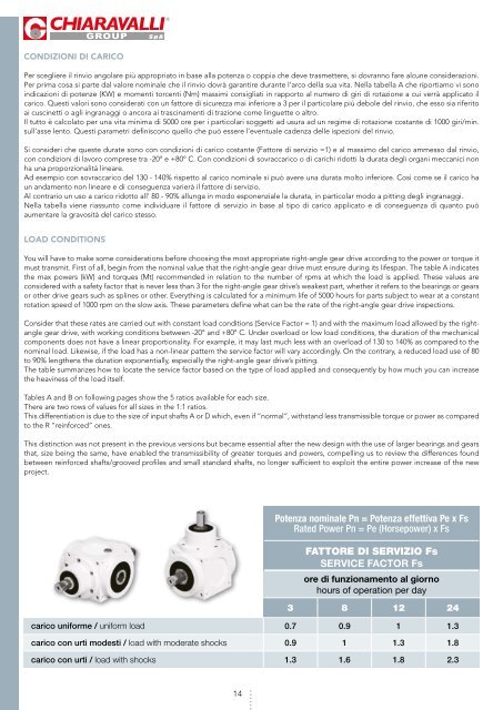
Potenza nominale Pn = Potenza effettiva Pe x Fs<br />
Rated Power Pn = Pe (Horsepower) x Fs<br />
FATTORE DI SERVIZIO Fs<br />
SERVICE FACTOR Fs<br />
ore di funzionamento al giorno<br />
hours of operation per day<br />
carico uniforme / uniform load<br />
carico con urti modesti / load w<strong>it</strong>h moderate shocks<br />
carico uniforme / uniform load<br />
carico con urti / load w<strong>it</strong>h shocks<br />
carico con urti modesti / load w<strong>it</strong>h moderate shocks<br />
3<br />
0.7<br />
0.9<br />
8<br />
0.9<br />
1<br />
12<br />
1<br />
1.3<br />
24<br />
1.3<br />
1.8<br />
carico con urti / load w<strong>it</strong>h shocks 1.3 1.6 1.8 2.3<br />
14