

KitchenAid JLG61P - JLG61P EN (F084155) Istruzioni per l'Uso
KitchenAid JLG61P - JLG61P EN (F084155) Istruzioni per l'Uso
KitchenAid JLG61P - JLG61P EN (F084155) Istruzioni per l'Uso

Create successful ePaper yourself
Turn your PDF publications into a flip-book with our unique Google optimized e-Paper software.
Installation<br />
LEVELLING<br />
Four skid feet are fitted which can be adjusted up or<br />
down to level the cooker.<br />
CONVERSION FOR USE ON BUTANE<br />
(G30) OR PROPANE (G31)<br />
Each burner requires the injector to be replaced and<br />
bypass screws adjusted or replaced as follows:<br />
STABILITY CHAIN<br />
A hole in the gas inlet valve bracket can be used to<br />
engage a stability chain.<br />
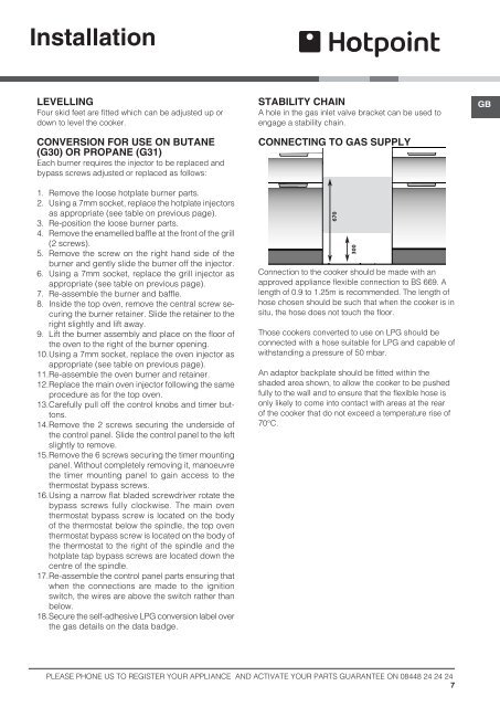
CONNECTING TO GAS SUPPLY<br />
GB<br />
1. Remove the loose hotplate burner parts.<br />
2. Using a 7mm socket, replace the hotplate injectors<br />
as appropriate (see table on previous page).<br />
3. Re-position the loose burner parts.<br />
4. Remove the enamelled baffle at the front of the grill<br />
(2 screws).<br />
5. Remove the screw on the right hand side of the<br />
burner and gently slide the burner off the injector.<br />
6. Using a 7mm socket, replace the grill injector as<br />
appropriate (see table on previous page).<br />
7. Re-assemble the burner and baffle.<br />
8. Inside the top oven, remove the central screw securing<br />
the burner retainer. Slide the retainer to the<br />
right slightly and lift away.<br />
9. Lift the burner assembly and place on the floor of<br />
the oven to the right of the burner opening.<br />
10. Using a 7mm socket, replace the oven injector as<br />
appropriate (see table on previous page).<br />
11. Re-assemble the oven burner and retainer.<br />
12. Replace the main oven injector following the same<br />
procedure as for the top oven.<br />
13. Carefully pull off the control knobs and timer buttons.<br />
14. Remove the 2 screws securing the underside of<br />
the control panel. Slide the control panel to the left<br />
slightly to remove.<br />
15. Remove the 6 screws securing the timer mounting<br />
panel. Without completely removing it, manoeuvre<br />
the timer mounting panel to gain access to the<br />
thermostat bypass screws.<br />
16. Using a narrow flat bladed screwdriver rotate the<br />
bypass screws fully clockwise. The main oven<br />
thermostat bypass screw is located on the body<br />
of the thermostat below the spindle, the top oven<br />
thermostat bypass screw is located on the body of<br />
the thermostat to the right of the spindle and the<br />
hotplate tap bypass screws are located down the<br />
centre of the spindle.<br />
17. Re-assemble the control panel parts ensuring that<br />
when the connections are made to the ignition<br />
switch, the wires are above the switch rather than<br />
below.<br />
18. Secure the self-adhesive LPG conversion label over<br />
the gas details on the data badge.<br />
670<br />
300<br />
Connection to the cooker should be made with an<br />
approved appliance flexible connection to BS 669. A<br />
length of 0.9 to 1.25m is recommended. The length of<br />
hose chosen should be such that when the cooker is in<br />
situ, the hose does not touch the floor.<br />
Those cookers converted to use on LPG should be<br />
connected with a hose suitable for LPG and capable of<br />
withstanding a pressure of 50 mbar.<br />
An adaptor backplate should be fitted within the<br />
shaded area shown, to allow the cooker to be pushed<br />
fully to the wall and to ensure that the flexible hose is<br />
only likely to come into contact with areas at the rear<br />
of the cooker that do not exceed a tem<strong>per</strong>ature rise of<br />
70°C.<br />
PLEASE PHONE US TO REGISTER YOUR APPLIANCE AND ACTIVATE YOUR PARTS GUARANTEE ON 08448 24 24 24<br />
7


