
You also want an ePaper? Increase the reach of your titles
YUMPU automatically turns print PDFs into web optimized ePapers that Google loves.
INDEX<br />
238 Aldo Bernardi G l i O t t o n i<br />
G l i O t t o n i Aldo Bernardi<br />
239<br />
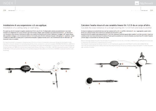
Installazione di una sospensione o di una applique.<br />
Installation of a ceiling lamp or wall lamp.<br />
Per questi due articoli è necessario scegliere canalette da ø 10 mm o da ø 16 mm. È indispensabile calcolare precedentemente il cavo totale<br />
necessario al collegamento tra il corpo luminoso e gli articoli ad esso collegati, quali ad esempio una scatola di derivazione A , un interruttore I<br />
o un successivo corpo luminoso. Posizionare la staffa a muro avendo l’accortezza di porre le barre filettate per il fissaggio a 45° rispetto all’asse<br />
della canaletta G. Collegare i cavi di conduzione elettrica H al morsetto posto all’interno della base lampada o dell’applique M , rispettando i simboli<br />
L (LINEA) ed N (NEUTRO). A questo punto si posizionerà la lampada o l’applique facendo uscire i cavi di alimentazione dai fori della base L ed<br />
inserendoli dentro la canaletta.<br />
For these two articles it is necessary to choose ducting of 10 mm ø or 16 mm ø. It is essential to previously calculate the total length of cable<br />
required for connection between the illuminating body and the articles connected to it, such as for example a DISTRIBUTION BOX (A), a SWITCH (I)<br />
or another illuminating body. Position the bracket on the wall taking care to place the threaded bars for fixing at 45° to the axis of the DUCTING (G).<br />
Connect the electrical WIRES (H) to the terminal located inside the base of the lamp or of the WALL LAMP (M), following the symbols L (LINE) and<br />
N (NEUTRAL). At this point position the lamp or the wall lamp bringing the feed cables out of the holes of the BASE (L) and inserting them inside<br />
the ducting.<br />
Calcolare l’esatta misura di una canaletta lineare (lin 1-2-3) da un corpo all’altro.<br />
Caculate the exact distance of a straight ducting (lin 1-2-3) from one body to another.<br />
Si misura la lunghezza tra le estremità dei due corpi (per esempio da CIL a CIL O, o da RAC a interruttore R , etc...) aggiungendo a questo valore<br />
50 mm se si utilizza l’articolo LIN 3 e 60 mm se si utilizzano gli articoli LIN 1 o LIN 2.<br />
Quindi far entrare la canaletta scelta dalla parte del CIL L sino a far combaciare l’estremità opposta della canaletta P con l’altro raccordo Q. Inserire la<br />
canaletta avendo l’accortezza di bilanciare l’eccedenza. Fissare quindi la canaletta ai vari raccordi utilizzando una chiave fissa. Per rendere l’impianto<br />
a tenuta stagna si raccomanda l’uso del teflon per isolare.<br />
Measure the length between the ends of the two bodies (for example from cil to CIL (O), or from RAC to SWITCH (R), etc.) adding 50 mm to this value<br />
if using article LIN 3 and 60 mm if using articles LIN 1 or LIN 2.<br />
Then bring the chosen ducting from the part of the CIL (L) until matching the opposite end of DUCTING (P) with the other CONNECTOR (Q).<br />
Then insert the ducting taking care to balance the excess then fixing the ducting to the various connectors using a fixed spanner. To make the system<br />
tight, use teflon to insulate.<br />
A<br />
H<br />
Q<br />
L<br />
M<br />
G<br />
P<br />
O<br />
R<br />
I