VBV-750B CCTV VOERTUIGSYSTEEM SYSTEME ... - Braun & Braun
VBV-750B CCTV VOERTUIGSYSTEEM SYSTEME ... - Braun & Braun
VBV-750B CCTV VOERTUIGSYSTEEM SYSTEME ... - Braun & Braun

Create successful ePaper yourself
Turn your PDF publications into a flip-book with our unique Google optimized e-Paper software.
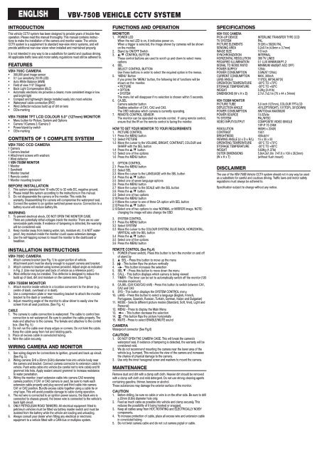
ENGLISH<br />
INTRODUCTION<br />
This vehicle <strong>CCTV</strong> system has been designed to provide years of trouble-free<br />
operation. Please read this manual thoroughly. This manual contains instructions<br />
to make the installation of the camera and monitor easier. The vehicle<br />
<strong>CCTV</strong> system is a supplement to standard rear-view mirror systems, and will<br />
provide additional rear-view vision when installed and maintained properly.<br />
It is not intended in any way to be a substitute for careful and cautious driving.<br />
All applicable traffic laws and motor safety regulations must still be adhered to.<br />
FEATURES<br />
<strong>VBV</strong>-700C CAMERA<br />
• 300,000 pixel image sensor<br />
• 0.1 Lux sensitivity (18 IR-LED)<br />
• Auto White Balance (AWB)<br />
• Field of view 110° Diagonal<br />
• Back Light Compensation (BLC)<br />
• Automatic electronic iris provides a clearer, more consistent image in low<br />
and bright light<br />
• Compact and lightweight design installed easily into most vehicles<br />
• Waterproof cable connection (IP67)<br />
• Wind deflector reduces build up of dirt on lens<br />
• CE/e-marking<br />
<strong>VBV</strong>-<strong>750B</strong>M TFT LCD COLOUR 5.0" (127mm) MONITOR<br />
• Menu button for Picture, System and Options<br />
• Camera 1/Camera 2 /Camera 3<br />
• Power/stand-by switch<br />
• CE/e-marking<br />
CONTENTS OF 1 COMPLETE SYSTEM<br />
<strong>VBV</strong>-700C CCD CAMERA<br />
1 Camera<br />
1 Camera bracket<br />
4 Attachment screws with washers<br />
1 Wind deflector<br />
1 <strong>VBV</strong>-<strong>750B</strong>M MONITOR<br />
1 Monitor<br />
1 Sunshield<br />
1 Monitor bracket<br />
1 Remote control<br />
1 Monitor mounting bracket<br />
BEFORE INSTALLATION<br />
1. This system operates from 10 volts DC to 32 volts DC, negative ground.<br />
2. Please install this system according to the instructions in this manual.<br />
3. Do not disassemble the camera or the monitor. This voids the<br />
warranty. Disassembling the camera will compromise the waterproof seal.<br />
4. Connect the system to an ignition switched power source. Connection to a<br />
battery source will reduce battery life.<br />
WARNING<br />
1. To prevent electrical shock, DO NOT OPEN THE MONITOR CASE.<br />
There are potentially lethal voltages inside the monitor. There are no user<br />
serviceable parts inside. If evidence of tampering is detected, the warranty<br />
will be considered void.<br />
2. Keep monitor away from leaking water, rain, moisture etc. It is NOT waterproof.<br />
Any moisture inside the monitor could cause extensive damage.<br />
3. Use the self-tapping screws to mount the monitor to the dashboard or<br />
headliner.<br />
INSTALLATION INSTRUCTIONS<br />
<strong>VBV</strong>-700C CAMERA<br />
1. Attach camera bracket (see Fig. 1) to upper portion of vehicle.<br />
Attachment point must be sturdy enough to support camera and bracket.<br />
2. Attach camera to bracket using screws provided. Adjust angle as indicated<br />
in Fig. 2. (Use rear bumper and back of vehicle as a reference point.)<br />
3. Wind deflector may be installed. This deflector is designed to reduce the<br />
build up of dust, dirt and moisture on the camera lens. (See Fig.3)<br />
<strong>VBV</strong>-<strong>750B</strong>M MONITOR<br />
1. Attach monitor inside vehicle in a location convenient to the driver (e.g.<br />
centre of dash, overhead or in dash).<br />
2. Use a compression plate or rear-mounting bracket to attach the monitor<br />
bracket to the dash or overhead.<br />
3. Adjust mounting angle of the monitor to allow driver to easily view the<br />
screen from all seat positions. (See Fig. 4.)<br />
CABLE<br />
1. The camera to cable connection is waterproof. The cable to control box<br />
connection is not waterproof. Be sure to position the cable properly. The<br />
male end attaches to the camera. The female end attaches to the control<br />
box. (See Fig. 5.)<br />
2. Do not run the cable over sharp edges or corners. Do not kink the cable.<br />
Keep the cable away from hot and rotating parts.<br />
3. Place all excess cable in convoluted tubing.<br />
4. Wire the cable securely.<br />
WIRING CAMERA AND MONITOR<br />
1. See wiring diagram for connections to ignition, ground and back up circuit.<br />
(See Fig. 5.)<br />
2. Wiring camera: Drill a 20mm (0.8in) diameter hole into vehicle body near<br />
the camera and bracket. Connect camera connector to extension cable in<br />
vehicle. Push extra cable into vehicle (be careful not to kink cable) and fit<br />
grommet into hole. Apply sealant around grommet to increase resistance<br />
to water penetration.<br />
3. Wiring the monitor: insert extension cable into camera CA3 reversing<br />
camera position; if CA1 or CA2 camera is used, be sure to mark each<br />
extension cable properly and plug second and third cable into camera<br />
CA1 or CA2 position. Bundle excess cable together using a cable tie or<br />
vinyl tape. This will avoid possible damage to cable during operation.<br />
4. The red wire is connected to an ignition power source, the black wire is<br />
connected to chassis ground, the brown wire is connected to the vehicle's<br />
back light circuit.<br />
5. ONLY PETROLEUM ROAD TANKERS: All electrical equipment fitted to<br />
petroleum vehicles must be fitted via battery master switch and must be<br />
isolated from the battery while the vehicle are loading and unloading.<br />
6. Always consult your dealer when fitting any electrical or electronic<br />
equipment to a vehicle fitted with a CAN-bus or multiplex system.<br />
<strong>VBV</strong>-<strong>750B</strong> VEHICLE <strong>CCTV</strong> SYSTEM<br />
FUNCTIONS AND OPERATION<br />
MONITOR<br />
1. POWER LED<br />
When the red LED is on, it indicates power on.<br />
When a trigger is selected, the image shown by cameras will be shown<br />
on the monitor.<br />
2. Stand by ON/OFF Switch<br />
3. ▲ /▼ CONTROL BUTTON<br />
These control buttons are used to scroll up and down to select menu<br />
options<br />
4. SEL.<br />
SELECT CONTROL BUTTON<br />
Use these buttons in order to select the required option in the menus.<br />
5. ‘MENU’ Button<br />
If you press the 'MENU' button, the following list of functions will be<br />
shown on the monitor.<br />
• PICTURE<br />
• OPTION<br />
• SYSTEM<br />
The menu list will disappear if no selection is chosen within 5 seconds.<br />
6. CA.SEL<br />
Camera selector button<br />
Enables selection of CA1, CA2 and CA3.<br />
The OSD indicates which camera is currently operating.<br />
7. REMOTE-CONTROL SENSOR<br />
The monitor can be operated via remote control. If using remote control,<br />
ensure that the IR on the remote control is facing the monitor.<br />
HOW TO SET YOUR MONITOR TO YOUR REQUIREMENTS<br />
1. PICTURE CONTROL<br />
1.1 Press the MENU button<br />
1.2 Select PICTURE<br />
1.3 Move the cursor to the VOLUME, BRIGHT, CONTRAST, COLOUR and<br />
SHARP with the SEL button<br />
1.4 Press the ▲ /▼ button<br />
1.5 Select one of five options<br />
1.6 Press the MENU button<br />
2. OPTION CONTROL<br />
2.1 Press the MENU button<br />
2.2 Select SEL<br />
2.3 Move the cursor to the LANGUAGE with the SEL button<br />
2.4 Press the ▲ /▼ button<br />
2.5 Select one of seven language options<br />
2.6 Press the MENU button<br />
2.7 Move the cursor to the SCALE with the SEL button<br />
2.8 Press the ▲ /▼ button<br />
2.9 Select one of two options<br />
2.10Press the MENU button<br />
2.11Move the cursor to one of three CA option with SEL button<br />
2.12Press the ▲ /▼ button<br />
2.13Select one of two options to view NORMAL or MIRROR image. NOTE:<br />
changing the image will also change the OSD<br />
3. SYSTEM CONTROL<br />
3.1 Press the MENU button<br />
3.2 Select SYSTEM<br />
3.3 Move the cursor to the COLOUR SYSTEM, BLUE BACK, HORIZONTAL,<br />
VERTICAL with the SEL button<br />
3.4 Press the ▲ /▼ button<br />
3.5 Select one of five options<br />
3.6 Press the MENU button<br />
REMOTE CONTROL (See Fig.A)<br />
1. POWER (Power switch). Press this button to turn the monitor on and off<br />
of stand by<br />
2. ▲ SEL - Press this button to move up the menu<br />
3. - This button flips the picture vertically<br />
4. + - This button increases the selection<br />
5. SEL ▼ - Press this button to move down the menu<br />
6. CALL - This button displays which camera is being viewed<br />
7. TIMER - The timer can be set to automatically switch off the monitor (120<br />
minutes maximum)<br />
8. CA.SEL (CA1/CA2/CA3 shift) - Press this button to switch between CA1,<br />
CA2 and CA3<br />
9. SYS - This button displays the SYSTEM CONTROL menu<br />
10. LANG - Press this button to select a language (English, French,<br />
Portuguese, Spanish, Russian, Turkish, German, Italian and Bulgarian)<br />
11. MODE - Selects different picture modes (Standard, Soft, Vivid, Light and<br />
Personal)<br />
12. MENU - Press to display the Main Menu<br />
13. - This button decrease the selection<br />
14. -This button flips the picture horizontally<br />
15. MUTE - Press to select ENABLE/MUTE sound<br />
▲▲<br />
CAMERA<br />
Waterproof connector (See Fig.6)<br />
CAUTION<br />
1. DO NOT OPEN THE CAMERA CASE. This will break the camera’s<br />
waterproof seal. If evidence of tampering is detected, the warranty will be<br />
considered void.<br />
2. We do not recommend mounting the camera near the lower area of the<br />
vehicle (e.g. bumper). This reduces the view of the camera and increases<br />
the chance of physical damage to the camera.<br />
3. Use only the inner hexagonal screw and washers to mount the camera.<br />
MAINTENANCE<br />
Remove dust and dirt with a damp soft cloth. Heavier dirt should be removed<br />
with a damp soft cloth and mild detergent. Do not use strong cleaning agents<br />
containing gasoline, thinner, benzene or alcohol.<br />
These substances may damage the exterior surface of the monitor.<br />
CAUTION<br />
1. Before drilling, be sure no cable or wire is on the other side. Be sure to drill<br />
a 20mm (0.8in) diameter hole only.<br />
2. Feed as much cable as possible into vehicle and clamp securely. This<br />
reduces the possibility of it being hooked or snagged.<br />
3. Keep all cables away from HOT, ROTATING and ELECTRICALLY NOISY<br />
components.<br />
4. To increase protection of cable, place all excess wire and extension cable<br />
in convoluted tubing.<br />
5. Do not twist camera cable and do not cut camera pigtail or cable.<br />
SPECIFICATIONS<br />
<strong>VBV</strong>-700C CAMERA<br />
PICK-UP DEVICE INTERLINE TRANSFER TYPE CCD<br />
TV SYSTEM PAL<br />
PICTURE ELEMENTS 512(H) x 582(V) PAL<br />
SENSING AREA 0.2x0.1in (4.9mm x 3.7mm)<br />
IMAGE SIZE 1/3 inch<br />
SYNCHRONIZATION INTERNAL<br />
HORIZONTAL RESOLUTION 380 TV LINES<br />
REQUIRED ILLUMINATION 0.1 LUX MINIMUM/F1.2<br />
SIGNAL TO NOISE RATIO MINIMUM 48dB(AT AGC OFF)<br />
POWER SUPPLY 12Vdc<br />
POWER CONSUMPTION 3.5W(AT 12Vdc)<br />
CURRENT CONSUMPTION MAX. 300mA<br />
LENS ANGLE 110º(D), 88º(H),66º(V)<br />
OPERATION TEMPERATURE -20ºC TO +70ºC<br />
STORAGE TEMPERATURE -30ºC TO +60ºC<br />
WEIGHT 0.2Kg (0.41lb)<br />
DIMENSIONS (W x H x D) 2.7x1.7x2.1in (70 x 44 x 54mm)<br />
<strong>VBV</strong>-<strong>750B</strong>M MONITOR<br />
PICTURE TUBE 5.0 inch (127mm), COLOUR TFT-LCD<br />
DEFLECTION ANGLE 45°(LEFT/RIGHT), 10°(TOP), 30°(DOWN)<br />
POWER CONSUMPTION 8W/700mA MAXIMUM<br />
POWER SOURCE 10-32Vdc<br />
TV SYSTEM PAL/NTSC<br />
VIDEO INPUT/OUTPUT COMPOSITE VIDEO SINGLE<br />
1VP-P 75 OHM<br />
RESOLUTION 960(H) x 234(V)<br />
CONTRAST 150:1<br />
BRIGHTNESS 400cd/m 2<br />
VIEWING ANGLE (U x D x R/L) 15 x 35 x 50<br />
OPERATING TEMPERATURE -20°C TO +70°C<br />
STORAGE TEMPERATURE -30°C TO +80°C<br />
WEIGHT 0.63Kg (1.37lb)<br />
OUTER DIMENSIONS 5.8x4.3x1.0in (147.6 x 109 x 26,5mm)<br />
(W x H x T) (without flush mount)<br />
DISCLAIMER<br />
The use of the <strong>VBV</strong>-<strong>750B</strong> Vehicle <strong>CCTV</strong> system should not in any way be used<br />
as a substitute for careful and cautious driving. Traffic laws and motor safety<br />
regulations must always be adhered to.<br />
Specification subject to change without any notice.