Download Vol.4 issue 3 - cchmedia.nl
Download Vol.4 issue 3 - cchmedia.nl
Download Vol.4 issue 3 - cchmedia.nl

Create successful ePaper yourself
Turn your PDF publications into a flip-book with our unique Google optimized e-Paper software.
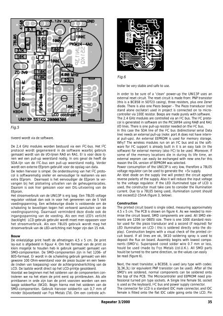
Fig.5<br />
tiveerd wordt via de software.<br />
De 2,4 GHz modules worden bestuurd via een I 2 C-bus. Het I 2 C<br />
protocol wordt gegenereerd in de software waarbij gebruik<br />
gemaakt wordt van de I/O-lijnen RA0 en RA1. Er is voor deze lijnen<br />
wel een pull-up weerstand nodig. In ons geval de heeft de<br />
SDA-lijn van de I 2 C-bus een pull-up weerstand nodig. Verder<br />
wordt een externe EEprom gebruikt voor de opslag van data.<br />
De reden hiervoor is simpel. De ondersteuning van het I 2 C protocol<br />
is softwarematig sneller en eenvoudiger te realiseren via een<br />
extra EEprom. Daarnaast is het eenvoudiger de EEprom te vervangen<br />
bij het plotseling uitvallen van de geheuge<strong>nl</strong>ocaties.<br />
Daarom is ook hier gekozen voor een DIL-uitvoering van de<br />
EEprom.<br />
Het stroomverbruik van de UNI13P is erg laag. Een 78L05 voltage<br />
regulator volstaat dan ook in voor het genereren van de 5 Volt<br />
voedingspanning. Een willekeurige diode is voldoende om de<br />
schakeling te beveiligen tegen het verkeerd aansluiten van de<br />
voedingsspanning. Daarnaast verminderd deze diode ook de<br />
ingangsspanning van de voeding. Als een met LED’s verlicht<br />
(backlight) LCD gebruik gebruikt wordt moet men oppassen voor<br />
het stroomverbruik. Als een 78L05 gebruik wordt mag het<br />
stroomverbruik van de LED-verlichting niet hoger zijn dan 15 mA.<br />
Bouw<br />
De enkelzijdige print heeft de afmetingen 4,5 x 5 cm. De print<br />
lay-out is afgebeeld in figuur 4. Om het formaat van de print zo<br />
klein mogelijk te houden heb ik gebruik gemaakt gemaakt van<br />
SMD-componenten. De SMD-componenten zijn in het 1206- of<br />
805-formaat. Er wordt in de schakeling gebruik gemaakt van één<br />
gewone 100 Ohm-weerstand voor de piezo buzzer en een tweede<br />
(indien van toepassing) voor de achtergrondverlichting van de<br />
LCD. De laatste wordt direct op het LCD-printje gesoldeerd.<br />
Voordat we beginnen met het solderen van de componenten controleren<br />
we na het etsen de print eerst op printbreuken. Als alle<br />
printbanen in orde zijn kan de print voorzien worden van een<br />
laagje soldeerflux (SK10). Begin hierna met het solderen van de<br />
SMD-componenten. Gebruik hiervoor soldeertin van 0,7 mm of<br />
minder (bijvoorbeeld van Frys Metals LTd). Om een controle ach-<br />
Fig.6<br />
troller be very stable and safe to use.<br />
In order to be sure of a 'clean' power-up the UNI13P uses an<br />
external reset circuit. The reset circuit is made from: PNP transistor<br />
(this is a BC858 in SOT23 casing), three resistors, plus one Zener<br />
diode. There is also one Piezo beeper - The Piezo transducer (not<br />
stand alone oscilator) used in project is connected on to microcontroller<br />
via 100E resistor. Beeps are made purely with software.<br />
The 2.4 GHz modules are controlled via an I 2C bus. The I 2C protocol<br />
is generated in software on the PIC16F84 using RAØ and RA1<br />
I/O lines. There is one pull-up resistor needed on the I 2C bus.<br />
In this case the SDA line of the I 2C bus (bidirectional serial Data<br />
line) needs an external pull-up (note: port A does not have internal<br />
pull-ups). An external EEPROM is used for memory storage.<br />
Why? The wireless modules run on an I 2C bus and as the software<br />
for I 2C support is already built in it is an easy task (in the<br />
software) for external memory (also I 2C) to be used. Moreover, if<br />
some of the memory locations die in during its life time, an<br />
external eeprom can easily be exchanged with new one.For this<br />
reason the DIL version of EEPROM was selected.<br />
Power consumption of the UNI13P is very low, therefore a 78L05<br />
voltage regulator can be used to generate the +5v supply.<br />
An Idiot diode on the supply line will protect the circuit against<br />
reverse polarity of the supply. Also it will reduce the input voltage<br />
to the voltage regulator. If the LED illuminated type of LCD is<br />
used, the constructor must take care to consider the illumination<br />
current. Due to a 78L05 being used, illumination current should<br />
not exceed12-15mA (figure 3, below).<br />
Construction<br />
The printed circuit board is single sided, measuring approximately<br />
4.5 x 5 cm. The PCB is shown on figure 4. As we needed to minimise<br />
the circuit board, SMD components are used. All SMD elements<br />
are 1206 (or 0805) size. There is one 100E standard resistor<br />
used for the piezo transducer and a second (if required) for<br />
LED illumination on LCD ( this is soldered directly onto the display).<br />
Construction begins with a visual check of the printed circuit<br />
board. If all lines are ok, SK10 soldering spray is used to<br />
deposit the flux on board. Assembly begins with lowest components<br />
(SMD's). Superspeed cored solder wire 0.7 mm or less,<br />
hould be used (made by Frys Metals Ltd.U.K.). All SMD parts<br />
hould be turned to the same direction, so the values can easily<br />
be read (figure 6).<br />
Next, the reset transistor, a BC858, is used (any type with codes:<br />
3J,3K,3L) (or equivalent PNP transistor can be used). After all the<br />
SMD's are soldered, normal components can be soldered onto<br />
the top of the PCB. The Microcontroller and EEPROM need professional<br />
turned pin type sockets. A Single line female SIL socket<br />
is used as the keyboard, I 2C bus and power supply connector.<br />
The connector for LCD is a standard IDC male connector, and IDC<br />
female is fitted onto the flat IDC cable going onto the LCD. Pin<br />
Repeater 3/2000 35