Handleiding montage - Termico
Handleiding montage - Termico
Handleiding montage - Termico

Create successful ePaper yourself
Turn your PDF publications into a flip-book with our unique Google optimized e-Paper software.
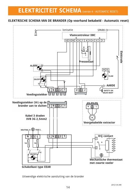
ELEKTRICITEIT SCHEMA (versie 4 - AUTOMATIC RESET)ELEKTRISCHE SCHEMA VAN DE BRANDER (Op voorhand bekabeld - Automatic reset)IonisatieSPARKVlamcontroleur DBCNN12 11 10 9 8 7 6 5 4 3 2 1Nc NocPressostaatElektrodeALARM14 13NVLAMON/OFFAARDEVoedingsstekker3N21NfLfSAFETY ONVALVE BODYVoedingsstekker (Vr) op debrander aan te sluiten3N21NLKabel 3 dradenXVB 3G 2,5mm2MVoorgekabelde extractorNEUTRAL NFASE LNL3N211Vrij contact1A1ACON/OFFSchakelkast type EEARMechanische thermostaatmet zwarte voelerUitwendige elektrische aansluiting van de brander142012-V4-AR