GB Cordless Driver Drill Instruction Manual F Perceuse ... - Makita
GB Cordless Driver Drill Instruction Manual F Perceuse ... - Makita
GB Cordless Driver Drill Instruction Manual F Perceuse ... - Makita

Create successful ePaper yourself
Turn your PDF publications into a flip-book with our unique Google optimized e-Paper software.
3. Charge the battery cartridge with room temperature<br />
at 10°C – 40°C (50°F – 104°F). Let a hot battery<br />
cartridge cool down before charging it.<br />
4. Charge the Nickel Metal Hydride battery cartridge<br />
when you do not use it for more than six<br />
months.<br />
OPERATING INSTRUCTIONS<br />
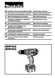
Installing or removing battery cartridge (Fig. 1)<br />
Always switch off the tool before insertion or removal of<br />
the battery cartridge.<br />
To remove the battery cartridge, withdraw it from the tool<br />
while pressing the buttons on both sides of the cartridge.<br />
To insert the battery cartridge, align the tongue on the<br />
battery cartridge with the groove in the housing and slip<br />
it into place. Always insert it all the way until it locks in<br />
place with a little click. If not, it may accidentally fall out<br />
of the tool, causing injury to you or someone around you.<br />
Do not use force when inserting the battery cartridge. If<br />
the cartridge does not slide in easily, it is not being<br />
inserted correctly.<br />
Installing or removing driver bit or drill bit (Fig. 2)<br />
Important:<br />
Always be sure that the tool is switched off and the battery<br />
cartridge is removed before installing or removing the bit.<br />
Hold the ring and turn the sleeve counterclockwise to<br />
open the chuck jaws. Place the bit in the chuck as far as<br />
it will go. Hold the ring firmly and turn the sleeve clockwise<br />
to tighten the chuck. To remove the bit, hold the ring<br />
and turn the sleeve counterclockwise.<br />
Switch action (Fig. 3)<br />
CAUTION:<br />
Before inserting the battery cartridge into the tool, always<br />
check to see that the switch trigger actuates properly and<br />
returns to the “OFF” position when released.<br />
To start the tool, simply pull the trigger. Tool speed is<br />
increased by increasing pressure on the trigger. Release<br />
the trigger to stop.<br />
Reversing switch action (Fig. 4)<br />
CAUTION:<br />
Always check the direction of rotation before operation.<br />
Use the reversing switch only after the tool comes to a<br />
complete stop. Changing the direction of rotation<br />
before the tool stops may damage the tool.<br />
This tool has a reversing switch to change the direction of<br />
rotation. Slide the reversing switch to the left for clockwise<br />
rotation or to the right for counterclockwise rotation.<br />
Adjusting fastening torque (Fig. 5)<br />
The fastening torque can be adjusted in six stages by<br />
turning the adjusting ring so that the pointer on the<br />
adjusting ring points to a number on the tool body. The<br />
fastening torque is minimum when the pointer points to<br />
the number 1 and maximum when it points to the<br />
u marking. The clutch will slip at varying torque<br />
levels when the pointer is set at the numbers 1 to 5. The<br />
clutch is designed not to slip at the u marking.<br />
Before actual operation, drive a trial screw into your<br />
material or a piece of duplicate material to determine<br />
which torque level is required for a particular application.<br />
4<br />
NOTE:<br />
The adjusting ring cannot be locked with the pointer positioned<br />
half-way between the numbers.<br />
Installing set plate (Fig. 6)<br />
Always install the set plate when using battery cartridges<br />
9100, 9102 or 9102A. Install the set plate on the tool with<br />
the screw provided as shown in Fig. 6.<br />
Screwdriving operation (Fig. 7)<br />
Place the point of the driver bit in the screw head and<br />
apply pressure to the tool. Start the tool slowly and then<br />
increase the speed gradually. Release the trigger as<br />
soon as the clutch cuts in.<br />
NOTE:<br />
Make sure that the driver bit is inserted straight in the<br />
screw head, or the screw and/or bit may be damaged.<br />
When driving wood screws, predrill pilot holes to make<br />
driving easier and to prevent splitting of the workpiece.<br />
See the chart.<br />
Nominal diameter<br />
of wood screw (mm)<br />
Recommended size<br />
of pilot hole (mm)<br />
3.1 2.0 – 2.2<br />
3.5 2.2 – 2.5<br />
3.8 2.5 – 2.8<br />
4.5 2.9 – 3.2<br />
4.8 3.1 – 3.4<br />
5.1 3.3 – 3.6<br />
<strong>Drill</strong>ing operation<br />
First, turn the adjusting ring so that the pointer on the<br />
adjusting ring points to the u marking. Then proceed<br />
as follows.<br />
<strong>Drill</strong>ing in wood<br />
When drilling in wood, best results are obtained with<br />
wood drills equipped with a guide screw. The guide<br />
screw makes drilling easier by pulling the bit into the<br />
workpiece.<br />
<strong>Drill</strong>ing in metal<br />
To prevent the bit from slipping when starting a hole,<br />
make an indentation with a centre-punch and hammer<br />
at the point to be drilled. Place the point of the bit in the<br />
indentation and start drilling.<br />
Use a cutting lubricant when drilling metals. The exceptions<br />
are iron and brass which should be drilled dry.<br />
CAUTION:<br />
Pressing excessively on the tool will not speed up the<br />
drilling. In fact, this excessive pressure will only serve<br />
to damage the tip of your bit, decrease the tool performance<br />
and shorten the service life of the tool.<br />
There is a tremendous force exerted on the tool/bit at the<br />
time of hole breakthrough. Hold the tool firmly and exert<br />
care when the bit begins to break through the workpiece.<br />
A stuck bit can be removed simply by setting the reversing<br />
switch to reverse rotation in order to back out. However,<br />
the tool may back out abruptly if you do not hold it firmly.<br />
Always secure small workpieces in a vice or similar<br />
hold-down device.