Fiat Bravo D Montage- und Betriebsanleitung Montage - Rameder ...
Fiat Bravo D Montage- und Betriebsanleitung Montage - Rameder ...
Fiat Bravo D Montage- und Betriebsanleitung Montage - Rameder ...

You also want an ePaper? Increase the reach of your titles
YUMPU automatically turns print PDFs into web optimized ePapers that Google loves.
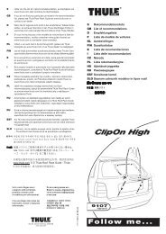
Installation Instructions:<br />
1.) Remove the rear bumper. Using the enclosed template, cut away the cutout from below.<br />
Remove the foam rubber parts from the rear apron.<br />
Remove the bolted metal supports from the rear apron; they are no longer required after<br />
the towing bracket has been fitted.<br />
Remove the rear exhaust bracket.<br />
Take the bottom covering out of the luggage compartment and lift up or remove the side trim<br />
panels.<br />
Remove the spare wheel from the spare-wheel well in the luggage compartment.<br />
Remove the blind rivet nuts and threaded studs at positions "c" where towing bracket "1"<br />
will make contact with the body.<br />
2.) Hold towing bracket "1" against the vehicle from the rear and below and align it exactly. Mark/<br />
prick-punch the positions for drilling the holes at positions "a" and "c" and take towing bracket<br />
"1" away again.<br />
Drill a Ø 11-mm hole at position "a" and a Ø 9-mm hole at positions "c". If necessary, drill<br />
out the holes at "c" to Ø 11 mm.<br />
3.) Lay reinforcement bracket "3" in the luggage compartment and align it at/bring it into contact<br />
with "a" and "b". Drill a Ø 9-mm hole at positions "b". Bolt towing bracket "1" loosely to the<br />
body and reinforcement bracket "3" at positions "a" using the M 10 x 30 hexagon bolts and<br />
M 10 hexagon nuts.<br />
At positions "b", bolt fishplate "8" to the body, towing bracket "1" and reinforcement bracket<br />
"3" using an M 8 x 25 hexagon bolt, 8.4 x 16 x 1.6 washers and M 8 hexagon nuts.<br />
Tightening torque at "b": M 8 = 20 Nm.<br />
Then bolt at "a" to:<br />
Tightening torque for M 10 = 40 Nm.<br />
Make sure the holes in towing bracket "1" at positions "c" align with the body.<br />
4.) Hold mounting brackets "5" (left) and "6" (right) beneath the vehicle and align it with the holes<br />
in the body at positions "c". The upper side of the mounting brackets must make contact with<br />
the <strong>und</strong>erside of the vehicle floor pan and the longitudinal axis of the mounting brackets must<br />
run parallel to the frame side member.<br />
Mark the position of the holes through the mounting brackets on the floor pan. Remove the<br />
brackets and drill a Ø 9-mm hole at positions "d". Pay attention to the cables laid in the<br />
luggage compartment. The hole clearance above the frame side members is 90 mm.<br />
At positions "d", play plates "4" in the luggage compartment, hold the mounting brackets<br />
against the floor pan from below and bolt loosely at positions "c" and "d" using the M 8 x 25<br />
hexagon bolts, 8.4 x 30 x 2 or 8.4 x 16 x 1.6 washers and M 8 hexagon nuts.<br />
Bolt first at positions "c" and then positions "d" to a<br />
tightening torque for M 8 = 20 Nm.<br />
5.) Slide towbar with mounting pipe "2" between the mounting plates and bolt is loosely at position<br />
"e" using the M 12 x 90 hexagon bolts, 13-mm washers and M 12 hexagon nuts. Bolt socket<br />
holder "7" in place in the rearward position.<br />
6.) Align the towing bracket and tighten all the nuts and bolts.<br />
Tightening torque at "e" for M 12 = 95 Nm<br />
7.) Put the spare wheel back in its well and refit the side trims panels and bottom covering.<br />
Refit the exhaust bracket.<br />
If possible, refit the foam rubber parts in the rear apron, cutting them to size.<br />
Refit the bumper.<br />
Subject to change.<br />
26<br />
GB<br />
Operating Instructions<br />
Note: • The lock nut is tightened and loosened without additional tools (i.e. by hand).<br />
• The supplied wrench is provided to assist, if necessary, in loosening the lock nut.<br />
• The mechanism is to be checked on a regular basis.<br />
• To ensure proper functioning and a long dependable operating life of the moving parts<br />
in the receiver pipe, the tow bar should be always be removed and the sealing plug fitted<br />
during journeys without a trailer.<br />
• If the visibility of the licence plate or the lights is impaired by the towing hitch, the towing<br />
hitch must be removed when a trailer is not being towed.<br />
• Always grease the tow bar before inserting.<br />
• The tow bar (even when not installed) must always be in the vehicle.<br />
• Attach the sign provided to the vehicle near the support tube or on the inside of the<br />
luggage compartment in a clearly visible location.<br />
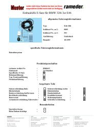
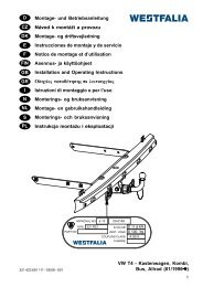
Bracket<br />
Marking (red)<br />
Coiled spring<br />
Balls<br />
Lock nut with<br />
cone thrust collar<br />
Stop ring<br />
Coiled spring<br />
Safety bore for<br />
coiled spring<br />
Receiver pipe<br />
Lock nut<br />
Spherical<br />
caps<br />
Marking (red)<br />
Tow bar<br />
Sealing plug<br />
GB<br />
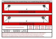
Tow Bar Removal and Installation<br />
Tow bar removal<br />
1.) Pull coiled spring out of safety bore.<br />
2.) Turn lock nut counterclockwise to stop<br />
ring.<br />
3.) Pull out tow bar.<br />
4.) Push in sealing plug and tighten lock nut by<br />
turning clockwise.<br />
Tow bar installation<br />
1.) Turn sealing nut counterclockwise to stop<br />
ring and pull out sealing plug.<br />
2.) Insert tow bar into receiver pipe as far as it<br />
will go. The red ring marking must no longer<br />
be visible.<br />
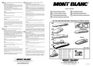
3.) Tighten lock nut by turning clockwise.<br />
The lock nut must be screwed on far enough<br />
that the coiled spring can pass through the<br />
safety bore (directly in front of the lock<br />
nut) through the receiver pipe and tow<br />
bar without difficulty (see illustration).<br />
Only when these conditions are fulfilled is the<br />
tow bar properly locked in place and may it<br />
be used.<br />
If the coiled spring does not fully protrude<br />
through the safety bore, the tow bar is not<br />
properly locked in place and, because of the<br />
associated accident risk, it must not be used<br />
<strong>und</strong>er any circumstances.<br />
To determine and rectify possible damage,<br />
consult an appropriate service center.<br />
27