Jøtul FS 280 Series - Jøtul stoves and fireplaces
Jøtul FS 280 Series - Jøtul stoves and fireplaces
Jøtul FS 280 Series - Jøtul stoves and fireplaces

Create successful ePaper yourself
Turn your PDF publications into a flip-book with our unique Google optimized e-Paper software.
English<br />
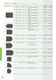
4.3 The surround consists of the following<br />
parts (Fig. 1C):<br />
Part Designation<br />
Quantity<br />
1 Bottom plate x1<br />
2 Screw, hexagon with flange M8 x 40 DIN6921 x8<br />
3 Leg x4<br />
4 Screw hexagon, M8x30 Elzn DIN 933 x4<br />
5 Protective hood, M8 6K black x4<br />
6 Threaded bar, M8 x 70 x4<br />
7 Long nut, M8 x 30 x4<br />
8 Allen nut with flange M8 untreated DIN 6923 x4<br />
9 Side plate x2<br />
10 Blind rivet nut M6 x8<br />
11 Mounting bracket x1<br />
12 Spacer sleeve heat shield x4<br />
13 Screw, hexagon with flange M6 x 10 special x4<br />
14 Nut M6 DIN 934 x4<br />
15 Heat shield front x1<br />
16 Sleeve Ø 10/6.2 x 10 x4<br />
17 Top plate x1<br />
18 Screw, machine countersunk poz M6 x 25<br />
black chrome DIN965<br />
x4<br />
19 Approval label x1<br />
20 Front plate x2<br />
21 Steel shelf x1<br />
22 Door damper Ø7, thickness 1.5 x3<br />
23 Ash lip, steel x1<br />
24 Rear piece x1<br />
25 Screw plate pan head poz 4.8 x 16 Elzn DIN 7981 x10<br />
Installation using top outlet<br />
The product is supplied from the factory with the smoke outlet<br />
fitted for the top outlet. See Fig. 5.<br />
• Thread the flue pipe (optional extra) through the top plate<br />
grate <strong>and</strong> place it in the smoke outlet.<br />
• Make sure that the gasket is properly seated between the flue<br />
pipe <strong>and</strong> the smoke outlet.<br />
• Fit the connection in the flue pipe.<br />
See measurements under “3.7 Steel chimney”.<br />
NB: It is important for the joints/flue pipes to be sealed completely.<br />
Air leaks may prevent them from operating properly.<br />
2. Screw the threaded bars onto the burn chamber. Tighten the<br />
screws (Fig. 8).<br />
3. Secure the console to the burn chamber using four nuts. Do<br />
not completely tighten the nuts. Allow a play of 3-4 mm. Adjust<br />
the long nuts to leave approximately 33-34 mm between the<br />
bottom plate (part 1) <strong>and</strong> the burn chamber. See Fig. 9.<br />
4. St<strong>and</strong> the burn chamber up with the help of another person.<br />
NB: Cover the floor to protect it from sharp edges.<br />
5. Refit the rear heat shield (cast iron) by first hanging it on the<br />
upper screws. Raise it slightly <strong>and</strong> slide it down onto the lower<br />
screws. Tighten the screws.<br />
6. Check that the fireplace is level.<br />
Measurements: There should be approx. 60 mm between the front<br />
of the console <strong>and</strong> the edge of the door. See Fig. 9.<br />
Installation of steel surrounding set (surround)<br />
1. Unscrew the four screws on the top of the burn chamber<br />
(Fig.10).<br />
2. Hold one of the side plates (part 9) <strong>and</strong> turn it so that the<br />
transversal holes are on the front.<br />
3. Fold down the lap at the bottom of the side (inside).<br />
4. Lift <strong>and</strong> turn the side approx. 45 o . Push it in between the legs<br />
of the console <strong>and</strong> angle it downwards.<br />
5. Do the same on the opposite side.<br />
6. Secure the sides with the mounting brackets (part 11). Hook<br />
the laps on the mounting brackets to the sides. Push the spacer<br />
sleeves under the plate <strong>and</strong> secure with screws.<br />
7. Fit four nuts <strong>and</strong> screws on the upper part of the sides (inside).<br />
See Fig. 11 A.<br />
8. Install the heat shield by attaching it in the keyhole opening.<br />
See Fig. 11 B.<br />
9. Mount both the front panels (part 20). See Fig. 12.<br />
10. Adjust the burn chamber, if necessary, by screwing the long<br />
nuts between the burn chamber <strong>and</strong> bottom plate. The<br />
distance between the burn chamber door <strong>and</strong> the upper front<br />
is 6 - 8 mm.<br />
11. Push the shelf (part 21) in from the side <strong>and</strong> let it rest against<br />
the bottom plate.<br />
12. Place door dampers (part 22) on the shelf <strong>and</strong> put the ash lip<br />
in place (part 23).<br />
13. Screw the rear plate into position with the screws supplied.<br />
14. With a rear outlet, remove the knockout.<br />
15. Fit the top plate as illustrated in Fig. 13.<br />
16. Fit the top grate on the knobs in the top plate. Turn the top<br />
grate so that the slots fit onto the knobs.<br />
Installation using a rear outlet<br />
Rear outlet can be installed in accordance with Fig. 1A+1B.<br />
Installation of console (Fig. 6)<br />
1. Secure an adjustment screw with protective hood into each<br />
of the four legs. Fit the bottom plate (part 1) to the legs. Use<br />
the four screws provided. Make sure that the legs are straight.<br />
Tighten the screws.<br />
Installation of console on the burn chamber<br />
1. Screw a long nut on each of the four threaded bars (part 7).<br />
The threaded bars must go 8-10 mm through the long nuts.<br />
See Fig. 7.<br />
16