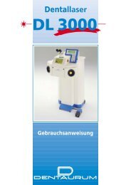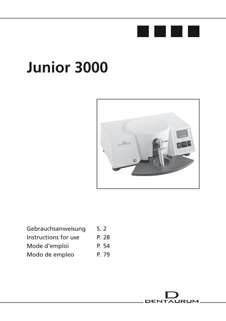
Junior 3000 Gebrauchsanweisung - DENTAURUM
Junior 3000 Gebrauchsanweisung - DENTAURUM
Junior 3000 Gebrauchsanweisung - DENTAURUM

Create successful ePaper yourself
Turn your PDF publications into a flip-book with our unique Google optimized e-Paper software.
<strong>Junior</strong> <strong>3000</strong><br />
<strong>Gebrauchsanweisung</strong> S. 2<br />
Instructions for use P. 28<br />
Mode d’emploi P. 54<br />
Modo de empleo P. 79
Hiermit erklären wir,<br />
<strong>DENTAURUM</strong> GmbH & Co. KG<br />
Turnstraße 31<br />
75228 Ispringen<br />
EG-Konformitätserklärung<br />
dass das nachfolgend bezeichnete Laborgerät aufgrund seiner Konzipierung und Bauart<br />
sowie in der von uns in Verkehr gebrachten Ausführung den einschlägigen grundlegenden<br />
Sicherheits- und Gesundheitsanforderungen der EG-Richtlinien entspricht.<br />
Bezeichnung des Laborgerätes: <strong>Junior</strong> <strong>3000</strong> (REF 077-000-00 / REF 077-000-01)<br />
Gerätetyp: Punktschweiß- und Lötgerät<br />
Ab Geräte-Nr.: 102-001 / 103-001<br />
EG-Richtlinien: EG-Richtlinie Elektromagnetische Verträglichkeit<br />
(89/336/EWG; i.d.F. 92/031/EWG)<br />
EG-Richtlinie Elektrische Betriebsmittel zur<br />
Verwendung innerhalb bestimmter Spannungs-<br />
grenzen<br />
(73/023/EWG)<br />
Änderungsrichtlinie für o.g. RL<br />
(93/068/EWG)<br />
Angewandte<br />
harmonisierte Normen: EN 55011/B<br />
EN 61000-4-2/4<br />
Datum/Hersteller-Unterschrift: 01.01.2010 ......................................................<br />
Angaben zum Unterzeichner: - i.V. Dipl. Ing. (FH) K. Merkle -<br />
Fertigungsleiter Gerätebau<br />
Druckdatum: 10.03.10<br />
DE<br />
junior <strong>3000</strong> de
Inhaltsverzeichnis Seite<br />
1. Sicherheitshinweise 5<br />
1.1 Bestimmungsgemäße Verwendung 5<br />
1.2 Symbole und Kennzeichnung von Gefahrenquellen 5<br />
1.3 Allgemeine Hinweise 6<br />
1.4 Entsorgung 6<br />
2. Einsatzbereich und Beschreibung 6<br />
2.1 Anwendung 6<br />
3. Technische Daten 6<br />
4. Lieferumfang 6<br />
5. Auspacken / Inbetriebnahme 7<br />
6. Bedienung des Gerätes 7<br />
6.1 Punktschweißen 7<br />
6.1.1 Punktschweißen mit dem „Click-Stop“-Elektrodenhalter 8<br />
6.1.2 Punktschweißen mit Handelektroden (Sonderzubehör) 9<br />
6.2 Löten 11<br />
6.2.1 Löten mit dem „Click-Stop“-Elektrodenhalter 12<br />
6.2.2 Löten mit Handelektroden (Sonderzubehör) 13<br />
6.2.3 Löten auf Modell 14<br />
6.3 Wärmebehandlung 14<br />
6.3.1 Weichglühen von Drähten 14<br />
6.3.2 Vergüten von Drähten 15<br />
6.3.3 Entspannen von Drähten 15<br />
6.3.4 Arbeitsablauf für Weichglühen, Vergüten, Entspannen 16<br />
7. Fehler und deren Behebung 17<br />
8. Dentaurum Technischer Kundendienst – Geräte 17<br />
9. Wartung und Pflege 17<br />
10. Ersatzteile für „Click-Stop“ Halterungen 18<br />
11. Sonderzubehör 19<br />
11.1 Ersatzteile für Handelektroden 19<br />
11.2 Montage der Halter für Handelektroden 20<br />
12. Blockschaltbild 21<br />
13. Schweißtabellen 23<br />
13.1 Noninium ® -Drähte 23<br />
13.2 remanium ® -Drähte 24<br />
13.3 remaloy ® -Drähte 25<br />
13.4 rematitan ® SPECIAL-Drähte 26<br />
13.5 Andere Materialien 27<br />
DE<br />
junior <strong>3000</strong> de 2
Bedienungselemente<br />
Gesamtabbildung<br />
<br />
<br />
<br />
<br />
<br />
<br />
<br />
b<br />
<br />
<br />
a<br />
<br />
<br />
DE<br />
junior <strong>3000</strong> de 3
Beschreibung<br />
Handauflage mit Elektrodenöffnungsmechanismus<br />
Unterer „Click-Stop“-Elektrodenhalter<br />
Oberer „Click-Stop“-Elektrodenhalter<br />
Handauslösetaste<br />
Netzkontroll-Lampe<br />
Schalter zur Auswahl der Betriebsart „Schweißen“ (Schweißsymbol a)<br />
oder „Löten“ (Lötsymbol b)<br />
Schalter zum Auswählen der Schweißstufen (I oder II)<br />
Steckbuchse für Handelektroden<br />
Steckbuchse für Handelektroden<br />
Kombistecker mit Netzschalter, Netzstecker und Sicherungsschalter<br />
Steckbuchse für Fußschalter<br />
Gehäuse mit Ablagemulde<br />
DE<br />
junior <strong>3000</strong> de 4
<strong>Gebrauchsanweisung</strong> <strong>Junior</strong> <strong>3000</strong><br />
230 V 50 / 60 Hz REF 077-000-00<br />
115 V 50 / 60 Hz REF 077-000-01<br />
Sehr geehrte Kundin, sehr geehrter Kunde<br />
Vielen Dank, dass Sie sich für ein Qualitätsprodukt aus dem Hause Dentaurum entschieden haben.<br />
Damit Sie dieses Produkt sicher und einfach zum größtmöglichen Nutzen für sich und die Patienten<br />
einsetzen können, muss diese Gebrauchs an wei sung sorgfältig gelesen und beachtet werden.<br />
In einer <strong>Gebrauchsanweisung</strong> können nicht alle Gegebenheiten einer möglichen Anwendung beschrieben<br />
werden. Deshalb steht Ihnen unsere Hotline gerne für Fragen und Anregungen zur Verfügung.<br />
Aufgrund der ständigen Weiterentwicklung unserer Produkte empfehlen wir Ihnen auch bei häufiger<br />
Verwendung des gleichen Produktes immer wieder das aufmerksame Durchlesen der jeweils aktuell<br />
beiliegenden bzw. im Internet unter www.dentaurum.de hinterlegten <strong>Gebrauchsanweisung</strong>.<br />
1. Sicherheitshinweise<br />
1.1 Bestimmungsgemäße Verwendung<br />
Das Gerät „<strong>Junior</strong> <strong>3000</strong>“ ist ausschließlich zum Schweißen und Löten von kieferorthopädischen<br />
Apparaturen bestimmt. Eine andere oder darüber hinausgehende Benutzung gilt als nicht<br />
bestimmungsgemäß. Zur bestimmungsgemäßen Verwendung gehört auch<br />
• das Beachten aller Hinweise aus der <strong>Gebrauchsanweisung</strong><br />
Das Punktschweißgerät „<strong>Junior</strong> <strong>3000</strong>“ ist nicht geeignet für den Einsatz bei prothetischen<br />
Arbeiten, insbesondere nicht zur Verarbeitung von<br />
- Edelmetalllegierungen<br />
- Modellgusslegierungen oder edelmetallfreien Legierungen für Keramik<br />
Bei der endgültigen Außerbetriebnahme des Dentaurum-Gerätes sind die entsprechenden<br />
landesspezifischen Vorschriften einzuhalten. Fragen zur sachgerechten Entsorgung des<br />
Dentaurum-Gerätes beantwortet Dentaurum oder der dentale Fachhandel.<br />
1.2 Symbole und Kennzeichnung von Gefahrenquellen<br />
In der <strong>Gebrauchsanweisung</strong> werden folgende Zeichen für Gefährdungen verwendet:<br />
Dieses Symbol bedeutet eine unmittelbare Gefahr für das Leben und die Gesundheit<br />
!! von Personen. Das Nichtbeachten dieser Hinweise kann schwere gesundheitsschädliche Auswirkungen<br />
zur Folge haben.<br />
! Dieses Symbol weist auf wichtige Anweisungen zur Sicherheit hin.<br />
Das Nichtbeachten dieser Hinweise kann die Sicherheit Ihres Gerätes und / oder das Eigentum<br />
anderer in Gefahr bringen.<br />
i<br />
Dieses Symbol gibt wichtige Hinweise für den sachgerechten Umgang mit dem Gerät.<br />
Das Nichtbeachten dieser Hinweise kann zu Störungen am Gerät führen.<br />
DE<br />
junior <strong>3000</strong> de 5
1.3 Allgemeine Hinweise<br />
• Tragen Sie bei jedem Schweiß- oder Lötvorgang eine Schutzbrille.<br />
!! • Um alle Einsatzmöglichkeiten des „<strong>Junior</strong> <strong>3000</strong>“ optimal nutzen zu können, beachten<br />
Sie vor Inbetriebnahme die nachfolgenden Hinweise sorgfältig.<br />
• Das Gerät arbeitet mit Hochspannung. Um Unfälle zu vermeiden, darf das Gerät<br />
nur vom Dentaurum Technischer Kundendienst – Geräte oder vom autorisierten<br />
Servicetechniker geöffnet werden.<br />
1.4 Entsorgung<br />
Hinweis:<br />
Dieses Symbol zeigt an, dass das damit gekennzeichnete Produkt nicht als normaler Haushaltsabfall<br />
entsorgt werden soll. Der Gesetzgeber verwehrt gewerblichen Kunden die Rückgabe<br />
von Altgeräten über kommunale Sammelstellen. Nähere Informationen erhalten Sie von<br />
Dentaurum oder dem dentalen Fachhandel.<br />
2. Einsatzbereich und Beschreibung<br />
2.1 Anwendung<br />
Das Punktschweißgerät „<strong>Junior</strong> <strong>3000</strong>“ erfüllt alle Voraussetzungen für das Herstellen von optimalen<br />
Schweiß- oder Lötverbindungen bei kieferorthopädischen Apparaturen:<br />
• Einstellen der Schweißenergie in 2 Stufen<br />
• Eine fest eingestellte Lötstufe<br />
• Ergonomisches Design<br />
• Anschlussmöglichkeit für Sonderzubehör<br />
3. Technische Daten<br />
Netzanschluss 230 V 50 / 60 Hz REF 077-000-00<br />
115 V 50 / 60 Hz REF 077-000-01<br />
Nennleistung 115 W<br />
Impulsstrom 1200 A<br />
Sicherung 2 A, träge (für 230 V); 3,15 A, träge (für 115 V)<br />
Isolierstoffklasse B<br />
Maße 335 x 310 x 130 mm (B x T x H)<br />
Gewicht ca. 7 kg<br />
Farbe Gehäuse RAL 9001 weiß<br />
Sockel und Handauflage RAL 1515 blau<br />
Auslösetaste RAL 9006 weiß-aluminium<br />
Das Typenschild mit der Gerätenummer befindet sich auf der Geräterückseite.<br />
4. Lieferumfang<br />
In der Grundausstattung sind enthalten:<br />
• „<strong>Junior</strong> <strong>3000</strong>“ Gerät • Netzkabel<br />
• Schraubendreher für Elektrodenwechsel • Schmirgelfeile für Lötelektroden<br />
• 1 x Ersatzsicherung • <strong>Gebrauchsanweisung</strong><br />
DE<br />
junior <strong>3000</strong> de 6
5. Auspacken / Inbetriebnahme<br />
Falls Sie wider Erwarten einen Transportschaden an Ihrem Gerät feststellen sollten, benachrichtigen<br />
Sie sofort den Dentaurum Technischer Kundendienst – Geräte (Seite 17) oder den Fachhändler,<br />
über den Sie das Gerät bezogen haben.<br />
! Achten Sie unbedingt vor Inbetriebnahme darauf, dass die Netzspannung mit den auf dem<br />
Typenschild (Geräterückwand) angegebenen Betriebsspannungen des Gerätes übereinstimmt.<br />
Stecken Sie das Netzkabel in den Netzkabelanschluss und schließen Sie das Gerät an das Netz<br />
an. Das Gerät ist danach betriebsbereit.<br />
6. Bedienung des Gerätes<br />
6.1 Punktschweißen<br />
Bei allen Schweißarbeiten Schutzbrille verwenden.<br />
!!<br />
! Bei Verwendung der Handelektroden zum Schweißen dürfen sich die Elektroden an den<br />
Elektrodenhaltern nicht berühren. Ansonsten fließt der Strom über die Elektrodenhalter<br />
und durch die Handelektroden, was zu schlechten Schweißergebnissen führt.<br />
Um den vielfältigen Erfordernissen beim Aufbau kieferorthopädischer Vorrichtungen gerecht<br />
zu werden, ist der „<strong>Junior</strong> <strong>3000</strong>“ mit 6 verschiedenen Kupferelektroden zum Schweißen<br />
ausgerüstet, die jeweils mit speziellen Kontaktspitzen oder -flächen versehen sind.<br />
Die „Click-Stop“-Elektrodenhalter , erlauben einen schnellen und einfachen Übergang von<br />
einer Elektrode zur anderen. Durch Drehen des Halters in die gewünschte Stellung rasten die<br />
Elektroden in der richtigen Position zueinander ein.<br />
Maximale Belastbarkeit des Gerätes:<br />
Soll das Gerät über mehrere Stunden betrieben werden, darf max. alle 5 Sekunden ein Schweißimpuls<br />
ausgelöst werden.<br />
Wird das Gerät jedoch nur einige Minuten betrieben (max. 30 min), so kann jede Sekunde ein<br />
Impuls erfolgen.<br />
Elektrodenkombinationen und Ausführungen<br />
zum Schweißen von:<br />
Brackets, Röhrchen,<br />
Häkchen und Ösen<br />
Obere Elektrode<br />
REF 085-000-00<br />
Untere Elektrode<br />
REF 086-000-00<br />
zum Schweißen von:<br />
Draht auf Draht<br />
Obere Elektrode<br />
REF 085-200-00<br />
Untere Elektrode<br />
REF 086-100-00 oder<br />
REF 086-300-00<br />
zum Schweißen von:<br />
Draht auf Bänder<br />
Obere Elektrode<br />
REF 085-100-00<br />
Untere Elektrode<br />
REF 086-200-00<br />
DE<br />
junior <strong>3000</strong> de 7
i Empfehlungen für Schweißstärkeneinstellung siehe gesonderte Tabelle (S. 22ff)<br />
i Hinweise:<br />
• Elektroden immer sauber halten.<br />
Saubere, polierte und richtig eingestellte Elektrodenspitzen sind für die Ausführung einwandfreier<br />
Schweißungen unerlässlich.<br />
• Zu schweißende Objekte sollten stets schmutz- und fettfrei sein und eine metallisch<br />
saubere Oberfläche aufweisen.<br />
Polieren der Spitzen<br />
Ein Stück Sandpapier (Körnung 600) mit der Schmirgelseite nach außen falten. Zwischen die<br />
Elektroden einführen. Sandpapier zwischen den Spitzen hin- und herdrehen, bis die ganze Ober fläche<br />
beider Spitzen poliert ist. Entstehenden Grat an Elektroden entfernen. Sollten die Elektroden nach<br />
längerer Betriebszeit nicht mehr voll funktionsfähig sein, können sie in den meisten Fällen zunächst<br />
mit der Elektrodenfeile REF 083-300-00 etwas nachgearbeitet werden. Sobald jedoch damit ein<br />
stärkerer Dimensionsverlust verbunden ist, wechseln Sie diese gegen neue Elektroden aus.<br />
Anwendungen:<br />
Brackets auf Band schweißen<br />
Beim Schweißen von Brackets auf Bandmaterial und vorgeformte Bänder ist darauf zu achten,<br />
dass die obere Elektrode ganz auf dem Aufschweißflansch des Brackets steht.<br />
Röhrchen auf Draht schweißen<br />
Die Röhrchenwand muss Kontakt mit dem Draht haben. Genügt der Elektrodendruck nicht, um<br />
den Kontakt herzustellen, empfiehlt es sich, das Röhrchen an der Kontaktstelle mit einer Zange<br />
etwas flachzudrücken.<br />
Draht auf Draht kreuzweise schweißen<br />
Normalerweise reicht eine Punktschweißung, bei der die Drähte kreuzweise aufeinandergelegt<br />
werden, aus, um eine optimale Verbindung zu erhalten. In vielen Einzelfällen kann es sinnvoll<br />
sein, die geschweißten Drähte zusätzlich noch zu verlöten. Hierbei ist aber zu berücksichtigen,<br />
dass der verstärkte Verbund durch das Löten einhergeht mit einer Verschlechterung der<br />
mechanischen Eigenschaften der Drähte infolge der Erwärmung beim Löten.<br />
Überprüfung einer Schweißung<br />
Eine qualitative Überprüfung der Schweißparameter für eine bestimmte Punktschweißung, z. B.<br />
Aufschweißteil (Bracket) auf Band, führt man am einfachsten optisch durch. Deutlich sichtbare<br />
hellbraune Punkte auf der Bandinnenseite zeugen von einer gelungenen Schweißung.<br />
6.1.1 Punktschweißen mit den „Click-Stop“-Elektrodenhaltern<br />
Arbeitsablauf:<br />
1. Netzschalter in Stellung „I“ bringen. Die grüne<br />
Netzkontrolllampe leuchtet. Das Gerät ist betriebsbereit.<br />
a<br />
2. Durch Drücken des Schalters auf Schaltposition a<br />
die Betriebsart „Schweißen” auswählen.<br />
<br />
<br />
<br />
DE<br />
b<br />
junior <strong>3000</strong> de 8
3. Die gewünschte Schweißenergie wird mittels Schalter eingestellt (Stufe I oder II).<br />
4. Handauflage nach unten drücken und Kupferelektroden in der gewünschten Kombination<br />
an den „Click-Stop“-Elektrodenhaltern und einrasten.<br />
5. Handauflage nach unten drücken und Schweißobjekt einlegen. Durch Verringerung des<br />
Handdruckes schließen sich die Elektroden exakt zueinander und fixieren das Schweißobjekt.<br />
6. Durch Betätigen des Handauslösers oder des Fußschalters (Sonderzubehör) wird der<br />
Schweißimpuls ausgelöst. 2 – 3 nebeneinandergesetzte Schweißimpulse genügen für eine<br />
einwandfreie Schweißverbindung.<br />
7. Schweißobjekt durch Druck auf die Handauflage lösen und gegebenenfalls Schweißung<br />
wiederholen.<br />
8. Nach Beenden des Schweißvorgangs wird das Gerät ausgeschaltet. Netzschalter in Stellung<br />
„0“ bringen.<br />
6.1.2 Punktschweißen mit Handelektroden (Sonderzubehör)<br />
Dieser Ablauf wird empfohlen, wenn z. B. Drähte gegeneinander auf dem Modell fixiert werden.<br />
Anschließend sollten die vom Modell abgenommenen Teile an den „Click-Stop“-Elektroden<br />
nachgeschweißt oder verlötet werden.<br />
Arbeitsablauf:<br />
1. Oberen Elektrodenkopf an der „Click-Stop“-<br />
Halterung um eine halbe Umdrehung nach<br />
rechts oder links (45°) schwenken.<br />
! Die obere und untere Elektrode dürfen<br />
sich nicht berühren.<br />
2. Die Stecker der Handelektroden in die Steckbuchsen<br />
und stecken.<br />
3. Netzschalter in Stellung „I“ bringen. Die<br />
grüne Netzkontrolllampe leuchtet. Das Gerät<br />
ist betriebsbereit.<br />
4. Durch Drücken des Schalters auf Schaltposition<br />
a die Betriebsart „Schweißen”<br />
auswählen.<br />
<br />
<br />
<br />
<br />
DE<br />
a<br />
<br />
<br />
b<br />
junior <strong>3000</strong> de 9
5. Die gewünschte Schweißenergie wird mittels des Schalters eingestellt (Stufe I oder Stufe II).<br />
6. Je eine gekerbte Elektrode REF 081-501-00 in die Spannhülsen der Handelektroden<br />
einspannen und dann mit den gekerbten Spitzen die zu schweißenden Objekte in kurzem<br />
Abstand zur Schweißstelle berühren. Die Kerben der Elektroden verhindern ein Abrutschen<br />
vom Drahtelement.<br />
7. Durch Betätigen des Handauslösers oder des Fußschalters wird der Schweißimpuls<br />
ausgelöst. 2 bis 3 Schweißimpulse genügen für eine einwandfreie Schweißverbindung.<br />
8. Nach Beenden des Schweißvorgangs wird das Gerät ausgeschaltet. Netzschalter in Stellung<br />
„0“ bringen.<br />
i Hinweis:<br />
Bei Handelektrodenschweißung ist die Schweißenergie höher einzustellen (Stufe 2) als bei der<br />
„Click-Stop“-Elektrodenhalterung. Die Einstellung der Schweißenergie richtet sich nach den<br />
jeweils zu bearbeitenden Materialquerschnitten, siehe gesonderte Tabelle (S. 22ff).<br />
Empfehlenswertes Sonderzubehör:<br />
Fußschalter REF 080-116-00 an Buchse anschließen.<br />
DE<br />
junior <strong>3000</strong> de 10
6.2 Löten<br />
Bei allen Lötarbeiten Schutzbrille verwenden. Dauert der Lötvorgang zu lange, wird<br />
!! die Lötkohle beschädigt.<br />
! Bei Verwendung der Handelektroden zum Löten oder zur Wärmebehandlung dürfen<br />
sich die Elektroden an den Elektrodenhaltern nicht berühren.<br />
Falls sich dennoch die Kupferelektroden berühren, erfolgt eine Fehlermeldung. Falls<br />
die Kohleelektrode eingesetzt wird, fließt der Strom über die Elektrodenhalter und<br />
durch die Handelektroden, was zu schlechten Lötergebnissen führt.<br />
• Beim Löten wird eine der Kupferelektroden gegen eine Kohleelektrode (Lötelektrode<br />
REF 085-300-00) ausgetauscht. Die elektrische Widerstandswärme speichert sich vorwiegend in<br />
der Kohlespitze, während die Metallteile selbst in geringem Maße Wärme aufnehmen. Durch<br />
die Mitverwendung von Lot und Flussmittel unterscheidet sich der Lötvorgang anordnungsgemäß<br />
vom Schweißen.<br />
• Beim elektrischen Löten erfolgt, bedingt durch die Kohleelektrode, eine kontinuierliche Erwärmung<br />
bis zur Verflüssigung des Lotes, wobei dieses dann die miterwärmten und durch das<br />
Flussmittel vor Oxidation geschützten Metallteile umfließt.<br />
• Vor jedem Löten muss die Kohleelektrode mit der Schmirgelfeile REF 083-300-00 gereinigt<br />
werden, um Flussmittelreste zu beseitigen, die infolge ihrer isolierenden Wirkung den Stromfluss<br />
bei der nächsten Lötung verhindern würden. Die Kohleelektrode muss rechtzeitig erneuert<br />
werden, bevor die Messingbuchse und der Elektrodenschaft anschmoren.<br />
• Zum Anspitzen der Lötkohle REF 081-601-00 empfehlen wir einen Bleistiftanspitzer. Die Leitfähigkeit<br />
der Lötkohle wird erhöht, wenn die Spitze vor dem Löten in Wasser getaucht wird.<br />
• Die Handelektroden sind nicht für Dauerlötungen geeignet.<br />
• Die Lötkohle setzt dem Strom einen größeren Widerstand entgegen als die Klemmelektrode<br />
REF 081-701-00. Die Hitze bildet sich also am Berührungspunkt der Lötkohle. Es ist daher<br />
darauf zu achten, dass die Lötkohlenspitze möglichst dort platziert wird, wo die Hitzeentwicklung<br />
die Teile nicht beschädigt.<br />
Lote<br />
Lötplättchen mit Flussmittelfüllung<br />
Arbeitstemperatur: 700 °C<br />
rund 25 Stück REF 381-001-00<br />
Fixieren des Lötplättchens auf dem Arbeitsstück<br />
mittels der Lötelektroden des Schweiß- und Lötgerätes.<br />
Die Kerbe vermeidet ein Abrutschen<br />
z. B. bei zu verlötenden Drähten.<br />
Universal Silberlot in Röhrenform, mit Flussmittel 1,2 g REF 380-604-50<br />
Arbeitstemperatur: 700 °C auf der Rolle, ohne Flussmittel 10 g REF 380-704-50<br />
Universal Silberlotpaste<br />
Arbeitstemperatur: 630 °C<br />
in Spritze, mit Flussmittel 7,5 g REF 380-804-50<br />
Dentaflux ® 50 g REF 681-100-00<br />
Universal-Lötpaste. Für alle Lötarbeiten in der<br />
Kieferorthopädie. Wenn erforderlich, mit wenig<br />
Wasser verdünnen.<br />
Weißgoldlot<br />
Arbeitstemperatur: 950 °C<br />
in Röhrenform, mit Flussmittel 1,8 g REF 380-600-50<br />
DE<br />
junior <strong>3000</strong> de 11
6.2.1 Löten mit „Click-Stop“-Elektrodenhalter<br />
Die zu verlötenden Teile zuvor mit einem Schweißpunkt heften.<br />
Arbeitsablauf:<br />
1. Netzschalter in Stellung „I“ bringen. Die grüne Netzkontrolllampe leuchtet.<br />
2. Durch Drücken des Schalters die Betriebsart ”Löten” auswählen (Schalterposition b).<br />
Schalter ist in der Betriebsart Löten ohne Funktion.<br />
3. Elektroden auf Elektrodenkombination A oder B einstellen (vgl. Abb. unten).<br />
4. Das Lötobjekt mit Flussmittel bestreichen und Lot auflegen bzw. Universal Silberlotpaste<br />
(REF 380-804-50) auftragen.<br />
5. Handauflage nach unten drücken und das Lötobjekt zwischen die Elektroden einlegen.<br />
6. Die Kohleelektrode ohne Druck auf das Lötobjekt richten.<br />
7. Handauslöser oder den Fußschalter so lange betätigen, bis das Lot geschmolzen und der<br />
Lötvorgang beendet ist.<br />
i<br />
<br />
a<br />
<br />
<br />
b<br />
Hinweis: Es darf nur mit der Kohleelektrode gelötet werden.<br />
<br />
Elektrodenkombination:<br />
A<br />
B<br />
DE<br />
junior <strong>3000</strong> de 12
6.2.2 Löten mit Handelektroden (Sonderzubehör)<br />
Arbeitsablauf:<br />
! Die obere und untere Elektrode dürfen sich nicht berühren.<br />
1. Oberen Elektrodenkopf des „Click-Stop“-Elektrodenhalters um eine halbe Stufe (45°) nach<br />
rechts oder links schwenken.<br />
Die Sicherung schmilzt durch.<br />
<br />
2. Stecker der Handelektroden in die Buchsen und stecken.<br />
3. In die Spannbuchse der rechten und linken Handelektrode wird jeweils die Klemmelektrode<br />
REF 081-701-00 zum Halten des Lötobjektes und die Lötkohle REF 081-601-00 eingespannt<br />
(vgl. Abb. unten).<br />
4. Netzschalter in Stellung „I“ bringen. Die grüne Netzkontrolllampe leuchtet.<br />
5. Durch Drücken des Schalters die Betriebsart „Löten” auswählen (Schaltposition b). Der<br />
Schalter ist in der Betriebsart „Löten” ohne Funktion.<br />
6. Die durch Heftschweißung verbundenen Teile in der Klemmelektrode so nah wie möglich an<br />
der Lötstelle festklemmen.<br />
7. a) Bei Verwendung von Lot in Stangen- oder Rollenform, z. B. REF 380-604-50, REF 380-600-50<br />
oder REF 380-704-50, Flussmittel auftragen.<br />
b) Bei Verwendung von Pastenlot, z. B. REF 380-804-50, entfällt das Auftragen von<br />
Flussmittel, da die Paste dieses bereits enthält.<br />
8. Spitze der Lötkohle so nah wie möglich mit der Lötstelle in Kontakt bringen.<br />
9. Je nach verwendeter Lotart mit a) oder b) fortfahren.<br />
a) Fußschalter betätigen. Wenn die Lötstelle sich rötlich zu färben beginnt, Lot zugeben.<br />
b) Fußschalter betätigen, bis das Lot restlos geschmolzen ist.<br />
10. Wird das Gerät nicht weiter benutzt, Netzschalter in Stellung „0“ bringen.<br />
Handelektrode mit<br />
Lötkohle<br />
Handelektrode<br />
mit Klemmelektrode<br />
a<br />
<br />
<br />
b<br />
DE<br />
junior <strong>3000</strong> de 13
6.2.3 Löten auf Modell<br />
Für das Löten auf dem Modell wird die Klemmelektrode REF 081-701-00 gegen eine gekerbte<br />
Elektrode REF 081-501-00 ersetzt. Mit den beiden Handelektroden kann dann an jeder<br />
beliebigen Stelle am Modell gelötet werden. Hand-oder Fußschalterbetätigung.<br />
Elektrode, gekerbt REF 081-501-00<br />
6.3 Wärmebehandlung<br />
6.3.1 Weichglühen von Drähten<br />
Federharte Chrom-Nickel-Edelstahldrähte, z. B. remanium ® , können bei einer Temperatur von<br />
ca. 1100 °C (Glutfarbe hellrot) weichgeglüht werden.<br />
Weichgeglühte CoCr-Drähte können nicht mehr vergütet (gehärtet) werden!<br />
Starke Verformungen, besonders Biegungen um enge Radien bei dicken Drähten, z. B. Außenbogen<br />
von Face Bows, sollten nicht ohne vorhergehendes lokales Weichglühen der vorgesehenen<br />
Biegestelle durchgeführt werden. Das Weichglühen empfiehlt sich auch, um einem Draht über<br />
eine bestimmte Länge die Elastizität zu nehmen, z. B. bei einem passiven Lingual- oder Palatinalbogen.<br />
Weiterer Ablauf siehe 6.3.4.<br />
DE<br />
junior <strong>3000</strong> de 14
6.3.2 Vergüten von Drähten<br />
Cobalt-Basislegierungen, z. B. remaloy ® oder Crozat-Drähte, können vergütet (gehärtet) werden.<br />
Die Vergütung der Drahtelemente ist abhängig von der Zeit und von der Temperatur. Das zu<br />
vergütende Drahtelement mit den Handelektroden nur kurz erwärmen (Glutfarbe dunkelbraun).<br />
Temperatur ca. 470 °C.<br />
Es wird geraten, wegen der verschiedenen Drahtabmessungen über Versuche die optimalen<br />
Bedingungen zu erproben. Weiterer Ablauf siehe 6.3.4.<br />
6.3.3 Entspannen von Drähten<br />
Beim Biegen federharter Drähte entstehen Spannungen im kristallinen Gefüge. Mit der Wärmebehandlung<br />
kann das gebogene Drahtelement entspannt werden. Die Entspannung erfolgt,<br />
indem der Draht während einer kurzen Zeitspanne auf ungefähr 550 °C erhitzt wird (Glutfarbe<br />
dunkelrot).<br />
Bitte beachten, dass bei einer Entspannung von Drahtteilen auf dem Modell die Erwärmung<br />
länger dauert, da der Gips erhebliche Wärme absorbiert. Weiterer Ablauf siehe 6.3.4.<br />
DE<br />
junior <strong>3000</strong> de 15
6.3.4 Arbeitsablauf für Weichglühen, Vergüten, Entspannen<br />
Wichtig!<br />
1. Oberen Elektrodenkopf des „Click-Stop“-Elektrodenhalters um eine halbe Stufe (45°) nach<br />
rechts oder links schwenken.<br />
! Die obere und untere Elektrode dürfen sich nicht berühren.<br />
<br />
a<br />
<br />
<br />
b<br />
2. Handelektroden in Buchse und anschließen und die gekerbten Elektroden REF 081-501-00 in<br />
die Spannbuchsen spannen.<br />
3. Fußschalter an Buchse anschließen.<br />
4. Netzschalter in Stellung „I“ bringen. Die grüne Netzkontrolllampe leuchtet.<br />
5. Durch Drücken des Schalters die Betriebsart „Löten” auswählen (Schaltposition b).<br />
Der Schalter ist in der Betriebsart „Löten” ohne Funktion.<br />
6. Die gekerbten Elektrodenspitzen in dem Bereich des Drahtes, der wärmebehandelt werden<br />
soll, aufsetzen.<br />
7. Fußschalter nur so lange betätigen, bis der Draht die für die gewünschte Funktion erforderliche<br />
Temperatur-Farbe erreicht hat.<br />
Hellrot ca. 1100 °C Weichglühen<br />
Dunkelrot ca. 550 °C Entspannen<br />
Dunkelbraun ca. 470 °C Vergüten<br />
8. Schnell die Elektroden vom Draht entfernen. Fußschalter loslassen.<br />
9. Nach Beendigung der Wärmebehandlung Netzschalter in Stellung „0“ bringen.<br />
i Hinweis:<br />
• Zum Weichglühen von dicken Drähten empfehlen wir, diese auf eine wärmeleitfähige, hitzebeständige<br />
Unterlage zu legen, z. B. Graphitplatte.<br />
• Anstatt der gekerbten Elektrode REF 081-501-00 kann auch die Klemmelektrode REF 081-701-00<br />
in einer Handelektrode zum Halten des Drahtelementes verwendet werden.<br />
• Es empfiehlt sich, die beschriebenen Arbeitsabläufe für Weichglühen, Vergüten und<br />
Entspannen an verschiedenen Drähten zu erproben, um sich auf die Wärmebehandlungstechniken<br />
einzuarbeiten.<br />
! Vorsicht: Fußschalter bei dünnen Drähten nur kurz betätigen, damit die Drähte nicht verbrennen<br />
oder schmelzen!<br />
DE<br />
junior <strong>3000</strong> de 16
7. Fehler und deren Behebung<br />
Fehler Ursache Behebung<br />
1.0 Gerät eingeschaltet. 1.1 Netzverbindung fehlt 1.1.1 Gerät über das Netzkabel<br />
mit dem Netz verbinden<br />
Netzkontrolllampe an<br />
Gerät leuchtet nicht 1.1.2 Sicherung der Netz-<br />
steckdose überprüfen<br />
3.0 Eingestellte Schweiß- 3.1 Schweißstärke 3.1.1 Schalter auf<br />
leistung zu gering am Gerät zu schwach<br />
eingestellt<br />
Stufe II setzen<br />
!! Das Gerät arbeitet mit Hochspannung!<br />
Um Unfälle zu vermeiden, darf das Gerät nicht geöffnet werden. Ist ein Fehler nicht durch<br />
o.g. Maßnahmen zu beheben, wenden Sie sich bitte an unseren Dentaurum Technischer<br />
Kundendienst – Geräte (siehe unten).<br />
*Auswechseln der Sicherung:<br />
1.2 Gerätesicherung defekt 1.2.1 Sicherung austauschen.<br />
* Sicherungswechsel<br />
(siehe unten)<br />
2.0 Schweiß- und 2.1 Elektroden oder Lötkohle 2.1.1 Elektroden, Lötkohle<br />
Lötleistung zu gering verschmutzt bzw. säubern oder aus-<br />
abgenutzt tauschen<br />
Dazu den Sicherungseinsatz an der rechten Seite des Kombisteckers entriegeln und herausziehen.<br />
Sicherung ist nun zugänglich und kann dem Sicherungseinsatz entnommen werden.<br />
! Vor dem Herausziehen des Sicherungseinsatzes Netzstecker ziehen!<br />
8. Dentaurum Technischer Kundendienst – Geräte<br />
Dentaurum Technischer Kundendienst – Geräte<br />
Dentaurum GmbH & Co. KG · Turnstraße 31 · 75228 Ispringen · Germany<br />
(P.O.B. 100 440, 75104 Pforzheim)<br />
Telefon + 49 72 31 / 803 - 211<br />
Telefax + 49 72 31 / 803 - 295<br />
E-Mail: info@dentaurum.de<br />
9. Wartung und Pflege<br />
Das Gerät ist wartungsfrei.<br />
Lediglich die Kupferelektroden sind je nach Gebrauch nachzufeilen. Ebenso empfiehlt es sich, die<br />
Kohleelektroden nach Gebrauch von Flussmittelresten zu reinigen.<br />
Bei Bedarf Haube mit trockenem oder angefeuchtetem Tuch abwischen. Keine scharfen<br />
Reinigungsmittel verwenden!<br />
i Keine heißen Gegenstände auf die Ablagemulde legen.<br />
i<br />
Die Elektroden<br />
müssen flach<br />
zueinander aufliegen.<br />
DE<br />
junior <strong>3000</strong> de 17
10. Ersatzteile für „Click-Stop“-Halterungen<br />
Obere Elektroden Untere Elektroden<br />
Lötelektrode<br />
Schrauben zum Halten der Elektroden<br />
Schraubenzieher für<br />
Elektrodenwechsel<br />
Schmirgelfeile für<br />
Lötkohle<br />
REF 085-000-00<br />
1 Stück<br />
REF 085-100-00<br />
1 Stück<br />
REF 085-200-00<br />
1 Stück<br />
REF 085-300-00<br />
1 Stück<br />
REF 084-100-00<br />
10 Stück<br />
Ersatzkohleeinsatz für Lötelektrode<br />
Ersatzsicherung 2 A, träge (für 230 V)<br />
DE<br />
REF 086-000-00<br />
1 Stück<br />
REF 086-100-00<br />
1 Stück<br />
REF 086-200-00<br />
1 Stück<br />
REF 086-300-00<br />
1 Stück<br />
REF 085-400-00<br />
10 Stück<br />
REF 907-047-10<br />
1 Stück<br />
Ersatzsicherung 3,15 A, träge (für 115 V)<br />
REF 907-037-10<br />
1 Stück<br />
REF 083-100-00<br />
1 Stück<br />
REF 083-300-00<br />
10 Stück<br />
junior <strong>3000</strong> de 18
11. Sonderzubehör<br />
Fuß- oder Knieschalter<br />
kombiniert<br />
REF 080-116-00 1 Stück<br />
Handelektrode, einzeln<br />
REF 081-101-00 1 Stück<br />
11.1 Ersatzteile für Handelektroden<br />
Lötkohle<br />
mit Kupferummantelung<br />
für Handelektrode<br />
REF 081-601-00 1 Stück<br />
Klemmelektrode<br />
REF 081-701-00 1 Stück<br />
Halter für Handelektrode<br />
REF 081-204-00 1 Paar<br />
DE<br />
REF 081-205-00 Halter rechts<br />
REF 081-206-00 Halter links<br />
Elektroden, gekerbt,<br />
zum Weichglühen, Vergüten,<br />
Schweißen<br />
REF 081-501-00 2 Stück<br />
junior <strong>3000</strong> de 19
11.2 Montage der Halter für Handelektroden<br />
REF 081-204-00 / 081-205-00 / 081-206-00<br />
Benötigtes Werkzeug: Schraubendreher (Kreuzschlitz)<br />
DE<br />
Das Schweißgerät umdrehen und auf die Oberseite<br />
legen.<br />
Achtung: Nicht auf die Elektroden legen.<br />
!!<br />
Montage der Halter.<br />
Anschließen und Einsetzen der Handelektroden.<br />
junior <strong>3000</strong> de 20
12. Blockschaltbild<br />
DE<br />
junior <strong>3000</strong> de 21
Nr. Bezeichnung REF<br />
1 Sicherung 2 At (für 230 V) 907-047-10<br />
Sicherung 3,15 At (für 115 V) 907-037-10<br />
2 Gerätefuß 908-868-00<br />
3 Netzkabel 907-027-10<br />
4 Steuer-Leistungsplatine (230 V) 908-624-00<br />
Steuer-Leistungsplatine (115 V) 908-624-10<br />
5 Kontrollleuchte (230 V) 907-443-00<br />
Kontrollleuchte (115 V) 907-447-00<br />
6 Umschalter zweipolig 908-765-00<br />
7 Umschalter einpolig 908-765-10<br />
8 Relais 908-624-50<br />
9 Widerstand 47 Ω 908-138-00<br />
10 Diode 907-214-00<br />
1<br />
9 10<br />
5 6 7<br />
8<br />
4<br />
DE<br />
junior <strong>3000</strong> de 22
13. Schweißtabellen<br />
Die nachstehenden Tabellen geben eine Auflistung von Einstellwerten der Schweißenergie für verschiedene<br />
Materialien.<br />
Je nach konkretem Anwendungsfall und den verwendeten Materialien sowie Oberflächenzustand<br />
können abweichende Einstellwerte erforderlich sein!<br />
13.1 Noninium ® -Drähte<br />
Material 1 Material 2 Elektroden- Einstellung Einstellung Einstellung<br />
Kombination <strong>Junior</strong> <strong>3000</strong> Assistent <strong>3000</strong> Master <strong>3000</strong><br />
Noninium ® Draht Noninium ® Draht<br />
0,7 mm hart 0,7 mm hart<br />
REF 520-070-00 REF 520-070-00<br />
Noninium ® Draht Noninium ® Draht<br />
0,7 mm hart 0,8 mm hart<br />
REF 520-070-00 REF 520-080-00<br />
Noninium ® Draht Noninium ® Draht<br />
0,8 mm hart 0,8 mm hart<br />
REF 520-080-00 REF 520-080-00<br />
Noninium ® Draht Noninium ® Draht<br />
0,8 mm hart 0,9 mm hart<br />
REF 520-080-00 REF 520-090-00<br />
Noninium ® Draht Noninium ® Draht<br />
0,9 mm hart 0,9 mm hart<br />
REF 520-090-00 REF 520-090-00<br />
Noninium ® Draht Noninium ® Draht<br />
0,9 mm hart 1,2 mm hart<br />
REF 520-090-00 REF 520-120-00<br />
Noninium ® Draht Noninium ® Draht<br />
1,2 mm hart 1,2 mm hart<br />
REF 520-120-00 REF 520-120-00<br />
Noninium ® Draht Noninium ® Draht<br />
0,7 mm federhart 0,7 mm federhart<br />
REF 520-072-00 REF 520-072-00<br />
Noninium ® Draht Noninium ® Draht<br />
0,7 mm federhart 0,8 mm federhart<br />
REF 520-072-00 REF 520-082-00<br />
Noninium ® Draht Noninium ® Draht<br />
0,8 mm federhart 0,8 mm federhart<br />
REF 520-082-00 REF 520-082-00<br />
Noninium ® Draht Noninium ® Draht<br />
0,8 mm federhart 0,9 mm federhart<br />
REF 520-082-00 REF 520-092-00<br />
Noninium ® Draht Noninium ® Draht<br />
0,9 mm federhart 0,9 mm federhart<br />
REF 520-092-00 REF 520-092-00<br />
REF 085-200-00 und<br />
REF 086-100-00<br />
REF 085-200-00 und<br />
REF 086-100-00<br />
Stufe 2<br />
Stufe 2<br />
Stufe 3 – 4<br />
46 – 48<br />
Stufe 4 – 5 48 – 50<br />
REF 085-200-00 und Stufe 2<br />
Stufe 4 – 5 62 – 64<br />
REF 086-100-00 nur zum Fixieren<br />
REF 085-200-00 und Stufe 2<br />
Stufe 4 – 5 64 – 66<br />
REF 086-100-00 nur zum Fixieren<br />
REF 085-200-00 und Stufe 2<br />
Stufe 6 75 – 77<br />
REF 086-100-00 nur zum Fixieren<br />
REF 085-200-00 und Stufe 2<br />
Stufe 6 77 – 79<br />
REF 086-100-00 nur zum Fixieren<br />
DE<br />
REF 085-200-00 und Stufe 2 Stufe 6 88<br />
REF 086-100-00 nur zum Fixieren nur zum Fixieren nur zum Fixieren<br />
REF 085-200-00 und<br />
REF 086-100-00<br />
REF 085-200-00 und<br />
REF 086-100-00<br />
Stufe 2<br />
Stufe 2<br />
Stufe 4<br />
Stufe 5<br />
REF 085-200-00 und Stufe 2<br />
Stufe 5<br />
REF 086-100-00 nur zum Fixieren<br />
REF 085-200-00 und Stufe 2<br />
Stufe 6<br />
REF 086-100-00 nur zum Fixieren<br />
REF 085-200-00 und Stufe 2<br />
Stufe 6<br />
REF 086-100-00 nur zum Fixieren<br />
45 – 47<br />
49 – 51<br />
57 – 59<br />
71 – 73<br />
77 – 79<br />
junior <strong>3000</strong> de 23
13.2 remanium ® -Drähte<br />
Material 1 Material 2 Elektroden- Einstellung Einstellung Einstellung<br />
Kombination <strong>Junior</strong> <strong>3000</strong> Assistent <strong>3000</strong> Master <strong>3000</strong><br />
remanium ® Draht remanium ® Draht<br />
0,7 mm hart 0,7 mm hart<br />
REF 513-070-00 REF 513-070-00<br />
remanium ® Draht remanium ® Draht<br />
0,7 mm hart 0,8 mm hart<br />
REF 513-070-00 REF 513-080-00<br />
remanium ® Draht remanium ® Draht<br />
0,8 mm hart 0,8 mm hart<br />
REF 513-080-00 REF 513-080-00<br />
remanium ® Draht remanium ® Draht<br />
0,8 mm hart 0,9 mm hart<br />
REF 513-080-00 REF 513-090-00<br />
remanium ® Draht remanium ® Draht<br />
0,9 mm hart 0,9 mm hart<br />
REF 513-090-00 REF 513-090-00<br />
remanium ® Draht remanium ® Draht<br />
0,5 mm federhart 0,5 mm federhart<br />
REF 523-050-00 REF 523-050-00<br />
remanium ® Draht remanium ® Draht<br />
0,5 mm federhart 0,6 mm federhart<br />
REF 523-050-00 REF 523-060-00<br />
remanium ® Draht remanium ® Draht<br />
0,6 mm federhart 0,6 mm federhart<br />
REF 523-060-00 REF 523-060-00<br />
remanium ® Draht remanium ® Draht<br />
0,6 mm federhart 0,7 mm federhart<br />
REF 523-060-00 REF 523-070-00<br />
remanium ® Draht remanium ® Draht<br />
0,7 mm federhart 0,7 mm federhart<br />
REF 523-070-00 REF 523-070-00<br />
remanium ® Draht remanium ® Draht<br />
0,7 mm federhart 0,8 mm federhart<br />
REF 523-070-00 REF 523-080-00<br />
remanium ® Draht remanium ® Draht<br />
0,8 mm federhart 0,8 mm federhart<br />
REF 523-080-00 REF 523-080-00<br />
remanium ® Draht remanium ® Draht<br />
0,8 mm federhart 0,9 mm federhart<br />
REF 523-080-00 REF 523-090-00<br />
remanium ® Draht remanium ® Draht<br />
0,9 mm federhart 0,9 mm federhart<br />
REF 523-090-00 REF 523-090-00<br />
REF 085-200-00 und Stufe 2<br />
Stufe 5<br />
REF 086-100-00 nur zum Fixieren<br />
REF 085-200-00 und Stufe 2<br />
Stufe 5<br />
REF 086-100-00 nur zum Fixieren<br />
REF 085-200-00 und Stufe 2<br />
Stufe 6<br />
REF 086-100-00 nur zum Fixieren<br />
REF 085-200-00 und Stufe 2<br />
Stufe 6<br />
REF 086-100-00 nur zum Fixieren<br />
REF 085-200-00 und Stufe 2 Stufe 6<br />
REF 086-100-00 nur zum Fixieren nur zum Fixieren 88<br />
REF 085-200-00 und<br />
REF 086-100-00<br />
REF 085-200-00 und<br />
REF 086-100-00<br />
59 – 61<br />
61 – 63<br />
81 – 83<br />
85 – 87<br />
Stufe 2 Stufe 3 – 4 35 – 40<br />
Stufe 2 Stufe 3 – 4 43 – 47<br />
REF 085-200-00 und Stufe 2<br />
Stufe 4 47 – 50<br />
REF 086-100-00 nur zum Fixieren<br />
REF 085-200-00 und Stufe 2<br />
Stufe 4 47 – 50<br />
REF 086-100-00 nur zum Fixieren<br />
REF 085-200-00 und Stufe 2<br />
Stufe 4 – 5 60 – 63<br />
REF 086-100-00 nur zum Fixieren<br />
REF 085-200-00 und Stufe 2<br />
Stufe 6 63 – 65<br />
REF 086-100-00 nur zum Fixieren<br />
REF 085-200-00 und Stufe 2<br />
Stufe 6 73 – 78<br />
REF 086-100-00 nur zum Fixieren<br />
REF 085-200-00 und<br />
REF 086-100-00<br />
REF 085-200-00 und<br />
REF 086-100-00<br />
nein<br />
Stufe 6<br />
78 – 80<br />
nur zum Fixieren<br />
nein<br />
Stufe 6<br />
88<br />
nur zum Fixieren<br />
DE<br />
junior <strong>3000</strong> de 24
13.3 remaloy ® -Drähte<br />
Material 1 Material 2 Elektroden- Einstellung Einstellung Einstellung<br />
Kombination <strong>Junior</strong> <strong>3000</strong> Assistent <strong>3000</strong> Master <strong>3000</strong><br />
remaloy<br />
REF 085-200-00 und<br />
Stufe 2 Stufe 5 35 – 40<br />
® Draht remaloy ® Draht REF 086-100-00<br />
0,7 mm hart 0,8 mm hart<br />
REF 528-070-00 REF 528-080-00 Handelektroden<br />
REF 081-501-00<br />
nein<br />
Stufe 6 61 – 63<br />
nur zum Fixieren nur zum Fixieren<br />
remaloy<br />
REF 085-200-00 und<br />
Stufe 2 Stufe 6 40 – 45<br />
® Draht remaloy ® Draht REF 086-100-00<br />
0,7 mm hart 1,0 mm hart<br />
REF 528-070-00 REF 528-100-00 Handelektroden<br />
REF 081-501-00<br />
nein<br />
Stufe 6 65 – 67<br />
nur zum Fixieren nur zum Fixieren<br />
remaloy<br />
REF 085-200-00 und<br />
nein Stufe 6 45 – 50<br />
® Draht remaloy ® Draht REF 086-100-00<br />
0,8 mm hart 1,0 mm hart<br />
REF 528-080-00 REF 528-100-00 Handelektroden<br />
REF 081-501-00<br />
nein<br />
Stufe 6 73 – 75<br />
nur zum Fixieren nur zum Fixieren<br />
remaloy<br />
REF 085-200-00 und<br />
nein<br />
Stufe 6<br />
45 – 50<br />
® Draht remaloy ® Draht REF 086-100-00 nur zum Fixieren<br />
0,9 mm hart 0,9 mm hart<br />
REF 528-090-00 REF 528-090-00 Handelektroden<br />
REF 081-501-00<br />
nein<br />
Stufe 6 79 – 81<br />
nur zum Fixieren nur zum Fixieren<br />
remaloy<br />
REF 085-200-00 und<br />
nein<br />
Stufe 6<br />
50 – 55<br />
® Draht remaloy ® Draht REF 086-100-00 nur zum Fixieren<br />
0,9 mm hart 1,3 mm hart<br />
REF 528-090-00 REF 528-130-00 Handelektroden<br />
REF 081-501-00<br />
nein<br />
Stufe 6 83 – 86<br />
nur zum Fixieren nur zum Fixieren<br />
DE<br />
junior <strong>3000</strong> de 25
13.4 rematitan ® SPECIAL-Drähte<br />
Material 1 Material 2 Elektroden- Einstellung Einstellung Einstellung<br />
Kombination <strong>Junior</strong> <strong>3000</strong> Assistent <strong>3000</strong> Master <strong>3000</strong><br />
rematitan ® SPECIAL rematitan ® SPECIAL<br />
Draht Draht REF 085-200-00 und Stufe 1 Stufe 1 8 – 10<br />
0,40 mm 0,40 mm REF 086-300-00<br />
REF 766-600-00 REF 766-600-00<br />
rematitan ® SPECIAL rematitan ® SPECIAL<br />
Draht Draht REF 085-200-00 und Stufe 1 Stufe 1 10 – 12<br />
0,40 mm 0,45 mm REF 086-300-00<br />
REF 766-600-00 REF 766-601-00<br />
rematitan ® SPECIAL rematitan ® SPECIAL<br />
Draht Draht REF 085-200-00 und Stufe 1 Stufe 1 – 2 13 – 15<br />
0,45 mm 0,45 mm REF 086-300-00<br />
REF 766-601-00 REF 766-601-00<br />
rematitan ® SPECIAL rematitan ® SPECIAL<br />
Draht Draht REF 085-200-00 und Stufe 1 Stufe 2 19 – 22<br />
0,45 mm 0,41 x 0,56 mm REF 086-300-00<br />
REF 766-601-00 REF 766-602-00<br />
rematitan ® SPECIAL rematitan ® SPECIAL<br />
Draht Draht REF 085-200-00 und Stufe 1 Stufe 2 24 – 26<br />
0,45 mm 0,43 x 0,64 mm REF 086-300-00<br />
REF 766-601-00 REF 766-603-00<br />
rematitan ® SPECIAL rematitan ® SPECIAL<br />
Draht Draht REF 085-200-00 und Stufe 2 Stufe 2 22 – 24<br />
0,45 mm 0,48 x 0,64 mm REF 086-300-00 nur zum Fixieren<br />
REF 766-601-00 REF 766-604-00<br />
rematitan ® SPECIAL rematitan ® SPECIAL<br />
Draht Draht REF 085-200-00 und Stufe 2 Stufe 2 – 3 40 – 45<br />
0,43 x 0,64 mm 0,43 x 0,64 mm REF 086-300-00<br />
REF 766-603-00 REF 766-603-00<br />
rematitan ® SPECIAL rematitan ® SPECIAL<br />
Draht Draht REF 085-200-00 und Stufe 2 Stufe 3 40 – 45<br />
0,43 x 0,64 mm 0,48 x 0,64 mm REF 086-300-00 nur zum Fixieren<br />
REF 766-603-00 REF 766-604-00<br />
rematitan ® SPECIAL rematitan ® SPECIAL<br />
Draht Draht REF 085-200-00 und Stufe 2 Stufe 3 45 – 47<br />
0,48 x 0,64 mm 0,48 x 0,64 mm REF 086-300-00 nur zum Fixieren<br />
REF 766-604-00 REF 766-604-00<br />
DE<br />
junior <strong>3000</strong> de 26
13.5 Andere Materialien<br />
Material 1 Material 2 Elektroden- Einstellung Einstellung Einstellung<br />
Kombination <strong>Junior</strong> <strong>3000</strong> Assistent <strong>3000</strong> Master <strong>3000</strong><br />
Standard Prämolaren- Stufe 5 78 – 80<br />
Bänder REF 860-012-00 nur zum Fixieren nur zum Fixieren<br />
Hyrax ® II 12/10 und Dentaform ® REF 602-808-00<br />
Snap<br />
1. Molarenbänder<br />
Handelektroden<br />
REF 081-501-00<br />
nein<br />
REF 878-013-00 bzw. Stufe 6 88<br />
REF 879-013-00 nur zum Fixieren nur zum Fixieren<br />
Standard Prämolaren- Stufe 6 69 – 71<br />
Goshgarian Bänder REF 860-012-00 nur zum Fixieren nur zum Fixieren<br />
Palatinalbügel und Dentaform ® 0,9 mm<br />
Snap<br />
1. Molarenbänder<br />
Handelektroden<br />
REF 081-501-00<br />
nein<br />
REF 728-020-00 REF 878-013-00 bzw. Stufe 6 69 – 71<br />
REF 879-013-00 nur zum Fixieren nur zum Fixieren<br />
Standard Prämolaren- Stufe 6 69 – 71<br />
® remanium<br />
Quad Helix<br />
Bänder REF 860-012-00 nur zum Fixieren nur zum Fixieren<br />
und Dentaform® REF 728-100-01<br />
Snap Handelektroden<br />
1. Molarenbänder REF 081-501-00<br />
REF 878-013-00 bzw.<br />
nein<br />
Stufe 6 69 – 71<br />
REF 879-013-00 nur zum Fixieren nur zum Fixieren<br />
Lingual-/ Dentaform Snap II<br />
Palatinalschloss Band<br />
REF 728-110-00 REF 881-226-00<br />
Knöpfchen, Dentaform Snap II<br />
kurz Band<br />
REF 750-101-00 REF 881-226-00<br />
Häkchen Dentaform Snap II<br />
mit Setzlasche Band<br />
REF 750-401-00 REF 881-226-00<br />
Dentaform Snap II<br />
Knopfhäkchen<br />
REF 750-701-00 Band<br />
REF 881-226-00<br />
Bukkalröhrchen Dentaform Snap II<br />
konvertierbar Band<br />
REF 724-013-00 REF 881-226-00<br />
REF 085-200-00 und<br />
Stufe 2 Stufe 4 55 – 60<br />
REF 086-300-00<br />
REF 085-200-00 und<br />
Stufe 2 Stufe 4 55 – 60<br />
REF 086-300-00<br />
REF 085-200-00 und<br />
Stufe 2 Stufe 4 55 – 60<br />
REF 086-300-00<br />
REF 085-200-00 und<br />
Stufe 2 Stufe 4 55 – 60<br />
REF 086-300-00<br />
REF 085-200-00 und<br />
Stufe 2 Stufe 4 55 – 60<br />
REF 086-300-00<br />
DE<br />
junior <strong>3000</strong> de 27
<strong>DENTAURUM</strong> GmbH & Co. KG<br />
Turnstraße 31<br />
75228 Ispringen<br />
EEC-Declaration of Conformity<br />
hereby declares that the design and construction of the laboratory equipment described<br />
below, including the version marketed by us, comply with the basic regulations governing<br />
safety and health as stated in the EEC Guidelines. This declaration will become invalid if the<br />
laboratory equipment is modified or altered in any way without our prior consent.<br />
Unit: <strong>Junior</strong> <strong>3000</strong> (REF 077-000-00 / 077-000-01)<br />
Description of unit: Orthodontic spot welder and solderer<br />
Start with unit No.: 102-001 / 103-001<br />
EEC guidelines: 73/023/EEC Electrical equipment used within<br />
certain voltage limits<br />
Applied unified standards: EN 55011/B<br />
EN 61000-4-2/4<br />
89/336/EEC Electromagnetic compatibility<br />
92/031/EEC Modified Guideline<br />
93/068/EEC Modifications of the above<br />
guidelines<br />
Date and manufacturers signature: 01.01.2010 ------------------------------------------<br />
Signatory: - i.V. Dipl. Ing. (FH) K. Merkle -<br />
Production Manager Mechanic<br />
Printing Date: 10.03.10<br />
EN<br />
junior <strong>3000</strong> en
Contents page<br />
1. Safety information 31<br />
1.1 Appropriate handling 31<br />
1.2 Danger symbols and markings 31<br />
1.3 Safety notes 32<br />
1.4 Disposal 32<br />
2. Description and usage 32<br />
2.1 Application 32<br />
3. Technical data 32<br />
4. Components supplied 32<br />
5. Unpacking and start-up procedure 33<br />
6. Operating instructions 33<br />
6.1 Spot welding 33<br />
6.1.1 Spot welding with “click-stop” electrodes 34<br />
6.1.2 Spot welding with hand electrodes (optional accessory) 35<br />
6.2 Soldering 37<br />
6.2.1 Soldering with “click-stop” electrodes 38<br />
6.2.2 Soldering with hand electrodes (optional accessory) 39<br />
6.2.3 Soldering on the model 40<br />
6.3 Heat treatment 40<br />
6.3.1 Annealing of wires 40<br />
6.3.2 Tempering wires 41<br />
6.3.3 Stress relieving of wires 41<br />
6.3.4 Procedure for soft annealing, tempering and stress relieving 42<br />
7. Troubleshooting 43<br />
8. Dentaurum Customer Service 43<br />
9. Care and maintenance 43<br />
10. Spare parts for “click-stop” holders 44<br />
11. Optional accessories 45<br />
11.1 Spare parts for hand electrodes 45<br />
11.2 Installation of the holder for hand electrodes 46<br />
12. Schematic 47<br />
13. Welding chart 49<br />
13.1 Noninium ® wires 49<br />
13.2 remanium ® wires 50<br />
13.3 remaloy ® wires 51<br />
13.4 rematitan ® SPECIAL wires 52<br />
13.5 Other materials 53<br />
EN<br />
junior <strong>3000</strong> en 28
Features and Controls<br />
Overall View<br />
<br />
<br />
<br />
<br />
<br />
<br />
<br />
b<br />
<br />
<br />
a<br />
<br />
<br />
EN<br />
junior <strong>3000</strong> en 29
Description<br />
Hand operated platform with electrode opening mechanism<br />
Lower “click-stop” electrode holder<br />
Upper “click-stop” electrode holder<br />
Manual button<br />
On / Off light<br />
Switch for selecting “Welding” (weld symbol a)<br />
or “Soldering” (solder symbol b) modes<br />
Switch for selecting welding strength (I or II)<br />
Outlet for hand electrodes<br />
Outlet for hand electrodes<br />
Combination outlet with power-supply switch, power plug and fuse switch<br />
Outlet for foot switch<br />
Housing with tray<br />
EN<br />
junior <strong>3000</strong> en 30
Instructions for Use <strong>Junior</strong> <strong>3000</strong><br />
230 V 50 / 60 Hz REF 077-000-00<br />
115 V 50 / 60 Hz REF 077-000-01<br />
Dear Customer<br />
Thank you for having chosen a quality product from Dentaurum.<br />
In order to use this product at its best for you and your patients, it is important to study and follow<br />
these directions for use carefully.<br />
The written instructions cannot cover all eventualities during operation. For this reason our Hotline is<br />
available to answer any other questions and ideas that may arise.<br />
Due to a constant development we recommend, even when you use the same products frequently, to<br />
study the enclosed latest issue of the instructions for use or refer to our website at www.dentaurum.de.<br />
1. Safety information<br />
1.1 Appropriate handling<br />
The <strong>Junior</strong> <strong>3000</strong> is only intended for welding and soldering of orthodontic appliances.<br />
The use of the unit for any other purpose is prohibited.<br />
The use of the unit for its correct purpose also includes<br />
• compliance with all the instructions contained in this handbook.<br />
The <strong>Junior</strong> <strong>3000</strong> is not suitable for prosthetics work, in particular:<br />
- precious metal alloys<br />
- model casting alloys or non-precious metal alloys for ceramics.<br />
When a Dentaurum product is finally no longer in use the disposal regulations of that particular<br />
country apply. Dentaurum or the dental trade is available to answer questions regarding the<br />
correct disposal of any specific product.<br />
1.2 Danger symbols and markings<br />
In the instructions for use, the following symbols are used to indicate sources of danger to the<br />
user:<br />
This symbol indicates direct danger to the life or health of the user.<br />
!! Disregarding this warning may involve a serious risk to health.<br />
! This symbol indicates important safety instructions.<br />
Disregarding this warning may cause damage to the unit and/or other property.<br />
i<br />
This symbol gives important information on the correct use of the unit. Disregarding this<br />
information may cause the unit to malfunction.<br />
EN<br />
junior <strong>3000</strong> en 31
1.3 Safety notes<br />
!! • Always wear safety goggles when soldering or welding.<br />
• To use the <strong>Junior</strong> <strong>3000</strong> to its full advantage, study the following notes carefully<br />
before using it for the first time.<br />
• The unit requires high voltage. The unit should only be opened by Dentaurum<br />
Customer Service’s personnel or authorised service technicians to avoid accidents.<br />
1.4 Disposal<br />
Note:<br />
This symbol indicates, products marked with it should not be disposed off together with<br />
garbage of households. The legislator disallows commercial customers to return electronic<br />
waste via municipial collection points. Further information is available through Dentaurum or<br />
the dental trade.<br />
2. Description and usage<br />
2.1 Application<br />
The <strong>Junior</strong> <strong>3000</strong> spot-welding unit fulfils all the requirements for producing optimum weld or<br />
solder joints in orthodontic appliances:<br />
• 2-stage setting of welding energy<br />
• soldering stage with fixed setting<br />
• Ergonomic design<br />
• Outlets for special accessories<br />
3. Technical data<br />
Mains connection 230 V 50 / 60 Hz REF 077-000-00<br />
115 V 50 / 60 Hz REF 077-000-01<br />
Rated power 115 W<br />
Impulse current 1200 A<br />
Fuse 2 A, time-delay fuse (for 230 V); 3.15 A, time-delay fuse (for 115 V)<br />
Insulation class B<br />
Dimensions 335 x 310 x 130 mm (13 1/4’’ x 8’’ x 5 1/4’’) (W x D x H)<br />
Weight approx. 7 kg / 17 lbs.<br />
Color housing RAL 9001 white<br />
Base and hand rest RAL 1515 blue<br />
Manual button RAL 9006 white-aluminum<br />
The rating plate with the number is on the back of the unit.<br />
4. Components supplied<br />
The basic set contains the following items:<br />
• <strong>Junior</strong> <strong>3000</strong> unit • Power cable<br />
• Screwdriver for changing electrodes • File for solder electrodes<br />
• 1 x spare fuse • Instructions for use<br />
EN<br />
junior <strong>3000</strong> en 32
5. Unpacking and start-up procedure<br />
Should you notice any damage which may have occurred in transit, notify Dentaurum Customer<br />
Service (page 43) or the dealer you got the unit from without delay.<br />
! Before using the unit, ensure that the power supply voltage corresponds to the operating<br />
voltage stated on the rating plate on the back of the unit.<br />
Plug the power cable into the power cable outlet and then into the power supply outlet.<br />
The unit is now ready for operation.<br />
6. Operating instructions<br />
6.1 Spot welding<br />
Always wear goggles for welding work.<br />
!!<br />
! When using the hand electrodes for welding, the electrodes must not touch<br />
each other at the electrode holders, otherwise electric current will flow through the<br />
electrode holders and the hand electrodes, and cause poor welding results.<br />
In order to meet the complex requirements for constructing orthodontic appliances, the <strong>Junior</strong><br />
<strong>3000</strong> is fitted with six different copper electrodes for welding. These have special contact tips or<br />
surfaces.<br />
The “click-stop” electrode holders , permit quick and easy changing from one electrode to<br />
the other. When the holder is turned to the desired position, the electrodes click into the correct<br />
position with reference to one another.<br />
Maximum load on unit<br />
If the unit is being used over several hours, only one welding pulse at the most should be<br />
activated every 5 seconds.<br />
However, if it is only being used for a few minutes (max. 30 minutes) a pulse can be activated<br />
every second.<br />
Electrode combinations and designs<br />
for welding:<br />
brackets, tubes, hooks<br />
and loops<br />
Upper electrode<br />
REF 085-000-00<br />
Lower electrode<br />
REF 086-000-00<br />
for welding:<br />
wire to wire<br />
Upper electrode<br />
REF 085-200-00<br />
Lower electrode<br />
REF 086-100-00 or<br />
REF 086-300-00<br />
for welding:<br />
wires to bands<br />
Upper electrode<br />
REF 085-100-00<br />
Lower electrode<br />
REF 086-200-00<br />
EN<br />
junior <strong>3000</strong> en 33
i<br />
For recommended welding settings, see separate table (p. 48ff)<br />
i Notes:<br />
• Electrodes must always be clean.<br />
Clean, polished and correctly set electrode tips are essential for good welds.<br />
• Objects being welded must always be free of dirt and grease and have a clean metallic<br />
surface.<br />
Polishing the tips<br />
Fold a piece of sandpaper (grain 600) with the rough side outwards and push it between the<br />
electrodes. Draw the sandpaper back and forth between the tips until the entire surface of<br />
both tips is polished. Remove any burrs which are created on the electrodes. If the electrodes no<br />
longer function correctly after a longer period, they can generally be re-worked slightly using the<br />
electrode file REF 083-300-00. However, if the size of the electrode tip is affected, replace the<br />
electrode with a new one.<br />
Applications:<br />
Welding brackets to bands<br />
When welding brackets to band material or pre-formed bands, ensure that the upper electrode is<br />
positioned fully on the welding flange of the bracket.<br />
Welding tubes to wire<br />
The wall of the tube must be in contact with the wire. If the pressure of the electrode is not<br />
sufficient to make contact, it is suggested flattening the tube slightly at the contact point with<br />
pliers.<br />
Spot-welding crossed wires<br />
Where the wires are simply crossed, a single spot-weld is usually adequate to connect them<br />
properly. In many cases, it is advisable to solder the wires in addition to welding. In this case, take<br />
into account that heating the wires when soldering them to strengthen the joint also causes the<br />
mechanical properties of the wires to deteriorate.<br />
Checking a weld<br />
The simplest method is to make a visual check of the weld quality of a specific spot-weld, e.g.<br />
a weld-on component (bracket) onto a band. Clearly visible light brown points on the inside of<br />
the band indicate a successful weld.<br />
6.1.1 Spot welding with the “click-stop” electrodes<br />
Procedure:<br />
1. Turn power switch to position “I”. The green<br />
pilot light turns on. The unit is now ready for<br />
use.<br />
2. Press switch to position a to select the<br />
“Welding” mode.<br />
3. Set the desired welding energy at switch <br />
(stage I or II)<br />
<br />
EN<br />
a<br />
<br />
<br />
b<br />
junior <strong>3000</strong> en 34
4. Press hand rest down and set the desired combination of copper electrodes on the<br />
“click-stop” electrode holders and .<br />
5. Press hand rest down and insert workpiece. When the pressure on the hand rest is reduced,<br />
the electrodes close and fix the workpiece in position.<br />
6. Activate the welding pulse with the manual button or foot switch (special accessory).<br />
2-3 adjacent welding pulses are enough to create a perfect welded joint.<br />
7. Release the workpiece by pressing the hand rest and repeat the welding process if necessary.<br />
8. After completing the welding process, turn the unit off and turn the power switch to<br />
position “0”.<br />
6.1.2 Spot welding with hand electrodes (optional accessory)<br />
This process is recommended when wires have to be fixed against one another on the model.<br />
The components removed from the model should then be re-welded or soldered on the<br />
“click-stop” electrodes.<br />
Procedure:<br />
1. Turn the upper electrode head on the “click-stop”<br />
holder one half turn (45°) to left or right.<br />
! The upper and lower electrodes must<br />
not touch each other.<br />
2. Push the plugs of the hand electrodes into the<br />
outlets and .<br />
3. Turn power switch to position “I”. The green<br />
pilot light turns on. The unit is now ready for<br />
use.<br />
4. Press switch to position a to select the “Welding”<br />
mode.<br />
5. Set the desired welding energy at switch <br />
(stage I or II).<br />
<br />
<br />
<br />
<br />
EN<br />
a<br />
<br />
<br />
b<br />
junior <strong>3000</strong> en 35
6. Clamp a notched electrode REF 081-501-00 into each of the clamping sleeves of the manual<br />
electrodes and then touch the workpiece with the notched tips at a short distance from the<br />
welding point. The notches of the electrode prevent it from slipping off the wire element.<br />
7. Activate the welding pulse with the manual button or foot switch. 2 – 3 welding pulses are<br />
enough to create a perfect welded joint.<br />
8. After completing the welding process, turn the unit off and turn the power switch to<br />
position “0”.<br />
i Note:<br />
When welding with the hand electrodes, the welding power must be set higher (stage 2)<br />
than with the “click-stop” holder. The weld-thickness setting depends on the cross section of<br />
the material being welded. (See separate table, p. 48ff).<br />
Recommended accessory:<br />
Connect foot switch REF 080-116-00 to outlet .<br />
EN<br />
junior <strong>3000</strong> en 36
6.2 Soldering<br />
When soldering, always wear safety goggles. If soldering takes too long, the soldering<br />
!! carbon is damaged.<br />
! When using hand electrodes for soldering or heat-treating, the electrodes must not<br />
touch each other at the electrode holders. However, if they do touch one another, a<br />
fault signal is given. If the carbon electrode is used, the current flows through the<br />
electrode holder and through the hand electrodes, causing poor soldering results.<br />
• For soldering purposes, one of the copper electrodes is replaced by a carbon electrode<br />
(soldering electrode REF 085-300-00). The heat created by the electrical resistance is stored<br />
mainly in the carbon tip, whereas the metal parts themselves absorb only a slight amount of<br />
heat. The soldering process differs from the welding process by using solder and flux.<br />
• During electric soldering, the carbon electrode leads to continuous heating until the solder is<br />
melted. This then flows around the metal parts which are also heated and protected from<br />
oxidation by the flux.<br />
• Before soldering, the carbon electrode should be cleaned with the emery file, REF 083-300-00<br />
to remove any flux residues, which have an insulating effect and would hinder the flow of<br />
current during the next soldering operation. Replace the carbon electrode before the brass<br />
sleeve and the electrode shaft begin to char.<br />
• We recommend using a pencil sharpener to sharpen the soldering carbon REF 081-601-00.<br />
To increase the conductivity of the soldering carbon, dip the tip in water before beginning<br />
the soldering operation.<br />
• The hand electrodes are not suitable for continuous soldering.<br />
• The soldering carbon offers more resistance to the current than the clamping electrode<br />
REF 081-701-00, thus causing heat to build up in the tip of the soldering carbon. Always<br />
ensure that the carbon tip is placed where the heat cannot damage the parts.<br />
Solders<br />
Solder pellets with flux filling round 25 pcs REF 381-001-00<br />
Working temperature: 700 °C / 1292 °F<br />
Fix the solder tablet on the workpiece<br />
using the solder electrodes of the welding<br />
and soldering unit. The notch prevents it<br />
from slipping, e.g. when welding wires.<br />
Universal silver solder in rods, ready fluxed 1.2 g REF 380-604-50<br />
in rolls, without flux 10 g REF 380-704-50<br />
Working temperature: 700 °C / 1292 °F<br />
Universal silver solder paste<br />
Working temperature: 630 °C / 1166 °F<br />
in syringe with flux 7.5 g REF 380-804-50<br />
Dentaflux ® Universal soldering flux. For all types of<br />
orthodontic soldering. If necessary, dilute<br />
slightly with water.<br />
50 g REF 681-100-00<br />
White gold solder<br />
Working temperature: 950 °C / 1742 °F<br />
in rods, ready fluxed 1.8 g REF 380-600-50<br />
EN<br />
junior <strong>3000</strong> en 37
6.2.1 Soldering with the “click-stop” electrodes<br />
First tack weld the parts together with a weld spot.<br />
Procedure:<br />
1. Turn power switch to position “I”. The green pilot light turns on.<br />
2. Press switch to position b to select the “Soldering” mode. In “Soldering” mode, the switch <br />
has no function.<br />
3. Set the electrodes to combination A or B (cf. fig. below).<br />
4. Apply flux to the section to be soldered and add the solder or apply universal silver soldering<br />
paste (REF 380-804-50).<br />
5. Press the hand rest down and place the workpiece between the electrodes.<br />
6. Align the carbon electrode on the workpiece without applying pressure.<br />
7. Press the manual button or the foot switch until the solder is melted and the soldering<br />
process finished.<br />
i<br />
<br />
a<br />
<br />
<br />
b<br />
<br />
Note: Please always use the carbon soldering electrode.<br />
Electrode combination:<br />
A<br />
B<br />
EN<br />
junior <strong>3000</strong> en 38
6.2.2 Soldering with hand electrodes (optional accessory)<br />
Procedure:<br />
1. Turn the upper electrode head on the “click-stop” holder one half turn (45°) to left or right.<br />
! The upper and lower electrodes must not touch each other. The fuse will blow.<br />
<br />
2. Push the plugs of the hand electrodes into the outlets and .<br />
3. Clamp the electrode REF 081-701-00 for holding the workpiece and clamp the soldering<br />
carbon REF 081-601-00 into the clamping sleeve of the right and left hand electrode.<br />
(cf. fig. below)<br />
4. Turn power switch to position “I”. The green pilot light turns on.<br />
5. Press switch to position b to select the “Soldering” mode.<br />
In “Soldering” mode, the switch has no function.<br />
6. Clamp the tack-welded parts in the clamping electrode as close as possible to the soldering point.<br />
7. a) Apply flux when using solder in rods or in a roll, REF 380-604-50, REF 380-600-50 or<br />
REF 380-704-50.<br />
b) Flux is not applied when using soldering paste, REF 380-804-50, as the paste already<br />
contains flux.<br />
8. Place the tip of the soldering carbon as close as possible to the soldering point.<br />
9. Proceed as below a) or b) depending on the type of solder used.<br />
a) Press the foot switch. Apply the solder when the solder joint begins to turn red.<br />
b) Press the foot switch until the solder has completely melted.<br />
10. If the unit is no longer required, turn power switch to position “0”.<br />
Hand electrode with<br />
soldering carbon<br />
Hand electrode with<br />
clamping electrode<br />
a<br />
<br />
<br />
b<br />
EN<br />
junior <strong>3000</strong> en 39
6.2.3 Soldering on the model<br />
To solder on the model, replace the clamping electrode REF 081-701-00 with a notched electrode<br />
REF 081-501-00. Using both hand electrodes, it is now possible to solder at any position on the<br />
model. Operate with manual or foot switch.<br />
Notched electrode REF 081-501-00<br />
6.3 Heat treatment<br />
6.3.1 Annealing of wires<br />
Spring hard chrome nickel stainless steel wires (e.g. remanium ® ) can be soft annealed at a<br />
temperature of approx. 1100 °C / 2012 °F (heat color bright red).<br />
Soft annealed CoCr wires cannot be tempered (hardened)!<br />
Complex bending operations (especially around tight radii with thick wires, e.g. outer wires<br />
of face bows) should not be done without previous local annealing of the bending area. Soft<br />
annealing is also recommended for removing the elasticity from a wire over a certain length, e.g.<br />
with a passive lingual or palatal bow. Refer to 6.3.4 for the subsequent procedure.<br />
EN<br />
junior <strong>3000</strong> en 40
6.3.2 Tempering wires<br />
Cobalt based alloys, e.g. remaloy ® , or Crozat wires can be tempered (hardened). The tempering<br />
of the wire elements depends on the time and the temperature. Heat the wire element only<br />
briefly using the hand electrodes (heat color: dark brown) at a temperature of approx.<br />
470 °C / 878 °F.<br />
In view of the different wire dimensions, it is recommended to determine the optimum hardening<br />
conditions experimentally beforehand. Refer to 6.3.4 for the subsequent procedure.<br />
6.3.3 Stress relieving wires<br />
When spring hard wires are bent, stresses are created in their crystalline structure. The bent wire<br />
element can be stress relieved using a suitable heat treatment process. This is done by heating the<br />
wire to approx. 550 °C / 1022 °F over a short period of time. Heat color, dark red.<br />
Remember that stress relieving wire elements on the model takes longer as the plaster absorbs a<br />
considerable amount of heat. Refer to 6.3.4 for the subsequent procedure.<br />
EN<br />
junior <strong>3000</strong> en 41
6.3.4 Procedure for soft annealing, tempering and stress relieving<br />
Important!<br />
1. Turn the upper electrode head on the “click-stop” holder one half turn (45°) to left or right.<br />
! The upper and lower electrodes must not touch each other.<br />
<br />
2. Fit the hand electrodes into outlet and and clamp the notched electrodes<br />
REF 081-501-00 into the clamping sleeves.<br />
3. Connect the foot switch to outlet .<br />
a<br />
<br />
<br />
b<br />
4. Turn power switch to position “I”. The green pilot light turns on.<br />
5. Press switch to position b to select the “Soldering” mode.<br />
In “Soldering” mode, the switch has no function.<br />
6. Set the notched electrode tips in the area of the wire to be heat treated.<br />
7. Operate the foot switch until the wire has reached the temperature (color) for the desired heat<br />
treatment process.<br />
Bright red approx. 1100 °C / 2012 °F soft annealing<br />
Dark red approx. 550 °C / 1022 °F stress relieving<br />
Dark brown approx. 470 °C / 878 °F tempering<br />
8. Remove the electrodes quickly from the wire and release the foot switch.<br />
9. On completion of heat treatment, turn the power switch to position “0”.<br />
i Note:<br />
• To soft anneal thick wires, we recommend placing these on a conductive, heat-resistant<br />
base, e.g. a graphite slab.<br />
• Instead of the notched electrode REF 081-501-00, the clamping electrode REF 081-701-00<br />
in a hand electrode can be used to hold the wire element.<br />
• To practice the techniques necessary for soft annealing, tempering and stress relieving, we<br />
recommend experimenting with the different kinds of wire.<br />
! Caution: With thin wires only press the foot switch briefly to ensure the wires do<br />
not burn or melt!<br />
EN<br />
junior <strong>3000</strong> en 42
7. Troubleshooting<br />
Fault Cause Remedy<br />
1.0 Unit is switched 1.1 Not connected to 1.1.1 Connect unit to<br />
on but pilot light power supply power supply<br />
does not turn on 1.1.2 Check fuse at<br />
power outlet<br />
The unit operates under high voltage!<br />
!! To prevent accidents, never open the unit. If malfunctions cannot be corrected in the above<br />
ways, please contact Dentaurum Customer Service (see below).<br />
*Replacing the fuse:<br />
Unlock the fuse insert on the right-hand side of the combination plug and pull it out. The fuse<br />
is now accessible and can be removed from the fuse holder.<br />
! Pull out the power plug before removing the fuse holder.<br />
8. Dentaurum Customer Service<br />
1.2 Unit fuse defective 1.2.1 Replace fuse<br />
* (To change fuse,<br />
see below)<br />
2.0 Welding and 2.1 Electrodes or solder 2.1.1 Clean or replace<br />
soldering power carbon dirty electrodes or<br />
too low or worn solder carbon<br />
Dentaurum Customer Service<br />
Dentaurum GmbH & Co. KG · Turnstraße 31 · 75228 Ispringen · Germany<br />
(P.O.B. 100 440, 75104 Pforzheim)<br />
Tel. +49 72 31 / 803 - 211<br />
Fax +49 72 31 / 803 - 295<br />
E-Mail: info@dentaurum.de<br />
9. Care and maintenance<br />
The unit requires no maintenance.<br />
Only the copper electrodes require filing after use. Carbon electrodes must also be cleaned after<br />
use to remove flux residues. If necessary, wipe the cover with a dry or damp cloth. Do not use<br />
corrosive cleaning agents.<br />
i Do not place hot objects in the tray .<br />
i<br />
EN<br />
The electrodes must<br />
be positioned flat in<br />
relation to each other<br />
3.0 Welding power 3.1 Welding strength 3.1.1 Set switch to stage II<br />
set too low on unit set too low<br />
junior <strong>3000</strong> en 43
10. Spare parts for "click-stop” holders<br />
Upper electrodes Lower electrodes<br />
Soldering electrodes<br />
Screws for tightening electrodes<br />
Screwdriver for changing<br />
electrodes<br />
Emery file for soldering<br />
carbon<br />
REF 085-000-00<br />
1 piece<br />
REF 085-100-00<br />
1 piece<br />
REF 085-200-00<br />
1 piece<br />
REF 085-300-00<br />
1 piece<br />
REF 084-100-00<br />
10 pieces<br />
Spare carbon insert for soldering electrode<br />
Spare fuse 3,15 A, time-delay fuse (for 115 V)<br />
EN<br />
REF 086-000-00<br />
1 piece<br />
REF 086-100-00<br />
1 piece<br />
REF 086-200-00<br />
1 piece<br />
REF 086-300-00<br />
1 piece<br />
REF 085-400-00<br />
10 pieces<br />
Spare fuse 2 A, time-delay fuse (for 230 V)<br />
REF 907-047-10<br />
1 piece<br />
REF 907-037-10<br />
1 piece<br />
REF 083-100-00<br />
1 piece<br />
REF 083-300-00<br />
10 pieces<br />
junior <strong>3000</strong> en 44
11. Optional accessories<br />
Foot or knee switch<br />
combined<br />
REF 080-116-00 1 piece<br />
Hand electrode, single<br />
REF 081-101-00 1 piece<br />
11.1 Spare parts for hand electrodes<br />
Soldering carbon<br />
with copper jacket for<br />
hand electrode<br />
REF 081-601-00 1 piece<br />
Clamping electrode<br />
REF 081-701-00 1 piece<br />
Holder for hand electrode<br />
REF 081-204-00 1 pair<br />
REF 081-205-00 holder, right<br />
REF 081-206-00 holder, left<br />
Electrodes, notched<br />
for annealing, tempering,<br />
welding<br />
REF 081-501-00 2 pieces<br />
EN<br />
junior <strong>3000</strong> en 45
11.2 Installation of the holder for hand electrodes<br />
REF 081-204-00 / 081-205-00 / 081-206-00<br />
Tools required: Phillips screwdriver<br />
Turn the welding unit upside down.<br />
EN<br />
!! Do not place the welding unit on to the<br />
electrodes.<br />
Installation of the electrode holder.<br />
Connect the hand electrodes and place them into<br />
the holder.<br />
junior <strong>3000</strong> en 46
12. Schematic<br />
Fittings for various voltage variantes:<br />
Board<br />
Void<br />
Coil current 33 mA<br />
Selector switch<br />
Soldering/Welding<br />
Selector switch<br />
welding power<br />
Output voltage:<br />
EN<br />
junior <strong>3000</strong> en 47
N° Name REF<br />
1 Fuse 2 At (for 230 V) 907-047-10<br />
Sicherung 3,15 At (for 115 V) 907-037-10<br />
2 Unit base 908-868-00<br />
3 Power cable 907-027-10<br />
4 Control-power board (230 V) 908-624-00<br />
Control-power board (115 V) 908-624-10<br />
5 Control light (230 V) 907-443-00<br />
Control light (115 V) 907-447-00<br />
6 Change-over switch, double pole 908-765-00<br />
7 Change-over switch, double pole 908-765-10<br />
8 Relay 908-624-50<br />
9 Resistor 47 Ω 908-138-00<br />
10 Diode 907-214-00<br />
1<br />
9 10<br />
5 6 7<br />
8<br />
4<br />
EN<br />
junior <strong>3000</strong> en 48
13. Welding charts<br />
The following charts provide a list of settings of the weld energy for different materials.<br />
Different settings may be required depending on the specific application and materials as well<br />
as the condition of the surface!<br />
13.1 Noninium ® wires<br />
Material 1 Material 2 Electrode Setting Setting Setting<br />
combination <strong>Junior</strong> <strong>3000</strong> Assistent <strong>3000</strong> Master <strong>3000</strong><br />
Noninium ® wire Noninium ® wire<br />
0.7 mm hard 0.7 mm hard<br />
REF 520-070-00 REF 520-070-00<br />
Noninium ® wire Noninium ® wire<br />
0.7 mm hard 0.8 mm hard<br />
REF 520-070-00 REF 520-080-00<br />
REF 085-200-00 and<br />
REF 086-100-00<br />
REF 085-200-00 and<br />
REF 086-100-00<br />
Stage 2<br />
Stage 2<br />
Noninium ® wire Noninium ® wire<br />
Stage 2<br />
0.8 mm hard 0.8 mm hard<br />
REF 085-200-00 and<br />
only for tack<br />
REF 520-080-00 REF 520-080-00<br />
REF 086-100-00<br />
welding<br />
Noninium ® wire Noninium ® wire<br />
Stage 2<br />
0.8 mm hard 0.9 mm hard<br />
REF 085-200-00 and<br />
only for tack<br />
REF 520-080-00 REF 520-090-00<br />
REF 086-100-00<br />
welding<br />
Noninium ® wire Noninium ® wire<br />
Stage 2<br />
0.9 mm hard 0.9 mm hard<br />
REF 085-200-00 and<br />
only for tack<br />
REF 520-090-00 REF 520-090-00<br />
REF 086-100-00<br />
welding<br />
Noninium ® wire Noninium ® wire<br />
Stage 2<br />
0.9 mm hard 1.2 mm hard<br />
REF 085-200-00 and<br />
only for tack<br />
REF 520-090-00 REF 520-120-00<br />
REF 086-100-00<br />
welding<br />
Stage 3 – 4<br />
46 – 48<br />
Stage 4 – 5 48 – 50<br />
Stage 4 – 5 62 – 64<br />
Stage 4 – 5 64 – 66<br />
Stage 6 75 – 77<br />
Stage 6 77 – 79<br />
Noninium ® wire Noninium ® wire<br />
Stage 2 Stage 6 88<br />
1.2 mm hard 1.2 mm hard<br />
REF 085-200-00 and<br />
only for tack only for tack only for tack<br />
REF 520-120-00 REF 520-120-00<br />
REF 086-100-00<br />
welding welding welding<br />
Noninium ® wire Noninium ® wire<br />
0.7 mm spring hard 0.7 mm spring hard<br />
REF 085-200-00 and<br />
REF 520-072-00 REF 520-072-00<br />
REF 086-100-00<br />
Noninium ® wire Noninium ® wire<br />
0.7 mm spring hard 0.8 mm spring hard<br />
REF 085-200-00 and<br />
REF 520-072-00 REF 520-082-00<br />
REF 086-100-00<br />
Stage 2<br />
Stage 2<br />
Noninium ® wire Noninium ® wire<br />
Stage 2<br />
0.8 mm spring hard 0.8 mm spring hard<br />
REF 085-200-00 and<br />
only for tack<br />
REF 520-082-00 REF 520-082-00<br />
REF 086-100-00<br />
welding<br />
Noninium ® wire Noninium ® wire<br />
Stage 2<br />
0.8 mm spring hard 0.9 mm spring hard<br />
REF 085-200-00 and<br />
only for tack<br />
REF 520-082-00 REF 520-092-00<br />
REF 086-100-00<br />
welding<br />
Noninium ® wire Noninium ® wire<br />
Stage 2<br />
0.9 mm spring hard 0.9 mm spring hard<br />
REF 085-200-00 and<br />
only for tack<br />
REF 520-092-00 REF 520-092-00<br />
REF 086-100-00<br />
welding<br />
Stage 4<br />
Stage 5<br />
Stage 5<br />
Stage 6<br />
Stage 6<br />
45 – 47<br />
49 – 51<br />
57 – 59<br />
71 – 73<br />
77 – 79<br />
EN<br />
junior <strong>3000</strong> en 49
13.2 remanium ® wires<br />
Material 1 Material 2 Electrode Setting Setting Setting<br />
combination <strong>Junior</strong> <strong>3000</strong> Assistent <strong>3000</strong> Master <strong>3000</strong><br />
remanium ® wire remanium ® wire<br />
Stage 2<br />
0.7 mm hard 0.7 mm hard<br />
REF 085-200-00 and<br />
only for tack<br />
REF 513-070-00 REF 513-070-00<br />
REF 086-100-00<br />
welding<br />
remanium ® wire remanium ® wire<br />
Stage 2<br />
0.7 mm hard 0.8 mm hard<br />
REF 085-200-00 and<br />
only for tack<br />
REF 513-070-00 REF 513-080-00<br />
REF 086-100-00<br />
welding<br />
remanium ® wire remanium ® wire<br />
Stage 2<br />
0.8 mm hard 0.8 mm hard<br />
REF 085-200-00 and<br />
only for tack<br />
REF 513-080-00 REF 513-080-00<br />
REF 086-100-00<br />
welding<br />
remanium ® wire remanium ® wire<br />
Stage 2<br />
0.8 mm hard 0.9 mm hard<br />
REF 085-200-00 and<br />
only for tack<br />
REF 513-080-00 REF 513-090-00<br />
REF 086-100-00<br />
welding<br />
Stage 5<br />
Stage 5<br />
Stage 6<br />
Stage 6<br />
remanium ® wire remanium ® wire<br />
Stage 2 Stage 6<br />
0.9 mm hard 0.9 mm hard<br />
REF 085-200-00 and<br />
only for tack only for tack 88<br />
REF 513-090-00 REF 513-090-00<br />
REF 086-100-00<br />
welding welding<br />
remanium ® wire remanium ® wire<br />
0.5 mm spring hard 0.5 mm spring hard<br />
REF 085-200-00 and<br />
REF 523-050-00 REF 523-050-00<br />
REF 086-100-00<br />
remanium ® wire remanium ® wire<br />
0.5 mm spring hard 0.6 mm spring hard<br />
REF 085-200-00 and<br />
REF 523-050-00 REF 523-060-00<br />
REF 086-100-00<br />
59 – 61<br />
61 – 63<br />
81 – 83<br />
85 – 87<br />
Stage 2 Stage 3 – 4 35 – 40<br />
Stage 2 Stage 3 – 4 43 – 47<br />
remanium ® wire remanium ® wire<br />
Stage 2<br />
0.6 mm spring hard 0.6 mm spring hard<br />
REF 085-200-00 and<br />
only for tack Stage 4 47 – 50<br />
REF 523-060-00 REF 523-060-00<br />
REF 086-100-00<br />
welding<br />
remanium ® wire remanium ® wire<br />
Stage 2<br />
0.6 mm spring hard 0.7 mm spring hard<br />
REF 085-200-00 and<br />
only for tack Stage 4 47 – 50<br />
REF 523-060-00 REF 523-070-00<br />
REF 086-100-00<br />
welding<br />
remanium ® wire remanium ® wire<br />
Stage 2<br />
0.7 mm spring hard 0.7 mm spring hard<br />
REF 085-200-00 and<br />
only for tack Stage 4 – 5 60 – 63<br />
REF 523-070-00 REF 523-070-00<br />
REF 086-100-00<br />
welding<br />
remanium ® wire remanium ® wire<br />
Stage 2<br />
0.7 mm spring hard 0.8 mm spring hard<br />
REF 085-200-00 and<br />
only for tack Stage 6 63 – 65<br />
REF 523-070-00 REF 523-080-00<br />
REF 086-100-00<br />
welding<br />
remanium ® wire remanium ® wire<br />
Stage 2<br />
0.8 mm spring hard 0.8 mm spring hard<br />
REF 085-200-00 and<br />
only for tack Stage 6 73 – 78<br />
REF 523-080-00 REF 523-080-00<br />
REF 086-100-00<br />
welding<br />
remanium ® wire remanium ® wire<br />
Stage 6<br />
0.8 mm spring hard 0.9 mm spring hard<br />
REF 085-200-00 and<br />
no<br />
only for tack<br />
REF 523-080-00 REF 523-090-00<br />
REF 086-100-00<br />
welding<br />
remanium ® wire remanium ® wire<br />
Stage 6<br />
0.9 mm spring hard 0.9 mm spring hard<br />
REF 085-200-00 and<br />
no<br />
only for tack<br />
REF 523-090-00 REF 523-090-00<br />
REF 086-100-00<br />
welding<br />
78 – 80<br />
88<br />
EN<br />
junior <strong>3000</strong> en 50
13.3 remaloy ® wires<br />
Material 1 Material 2 Electrode Setting Setting Setting<br />
combination <strong>Junior</strong> <strong>3000</strong> Assistent <strong>3000</strong> Master <strong>3000</strong><br />
remaloy<br />
REF 085-200-00 and<br />
Stage 2 Stage 5 35 – 40<br />
® wire remaloy ® wire REF 086-100-00<br />
0.7 mm hard 0.8 mm hard<br />
REF 528-070-00 REF 528-080-00 Hand electrodes<br />
REF 081-501-00<br />
no<br />
Stage 6 only 61 – 63 only<br />
for tack welding for tack welding<br />
remaloy<br />
REF 085-200-00 and<br />
Stage 2 Stage 6 40 – 45<br />
® wire remaloy ® wire REF 086-100-00<br />
0.7 mm hard 1.0 mm hard<br />
REF 528-070-00 REF 528-100-00 Hand electrodes<br />
REF 081-501-00<br />
no<br />
Stage 6 only 65 – 67 only<br />
for tack welding for tack welding<br />
remaloy<br />
REF 085-200-00 and<br />
no Stage 6 45 – 50<br />
® wire remaloy ® wire REF 086-100-00<br />
0.8 mm hard 1.0 mm hard<br />
REF 528-080-00 REF 528-100-00 Hand electrodes<br />
REF 081-501-00<br />
no<br />
Stage 6 only 73 – 75 only<br />
for tack welding for tack welding<br />
remaloy<br />
REF 085-200-00 and<br />
no<br />
Stage 6 only<br />
45 – 50<br />
® wire remaloy ® wire REF 086-100-00 for tack welding<br />
0.9 mm hard 0.9 mm hard<br />
REF 528-090-00 REF 528-090-00 Hand electrodes<br />
REF 081-501-00<br />
no<br />
Stage 6 only 79 – 81 only<br />
for tack welding for tack welding<br />
remaloy<br />
REF 085-200-00 and<br />
no<br />
Stage 6<br />
50 – 55<br />
® wire remaloy ® wire REF 086-100-00 for tack welding<br />
0.9 mm hard 1.3 mm hard<br />
REF 528-090-00 REF 528-130-00 Hand electrodes<br />
REF 081-501-00<br />
no<br />
Stage 6 only 83 – 86 only<br />
for tack welding for tack welding<br />
EN<br />
junior <strong>3000</strong> en 51
13.4 rematitan ® SPECIAL wires<br />
Material 1 Material 2 Electrode Setting Setting Setting<br />
combination <strong>Junior</strong> <strong>3000</strong> Assistent <strong>3000</strong> Master <strong>3000</strong><br />
rematitan ® SPECIAL rematitan ® SPECIAL<br />
wire wire REF 085-200-00 and Stage 1 Stage 1 8 – 10<br />
0.40 mm 0.40 mm REF 086-300-00<br />
REF 766-600-00 REF 766-600-00<br />
rematitan ® SPECIAL rematitan ® SPECIAL<br />
wire wire REF 085-200-00 and Stage 1 Stage 1 10 – 12<br />
0.40 mm 0.45 mm REF 086-300-00<br />
REF 766-600-00 REF 766-601-00<br />
rematitan ® SPECIAL rematitan ® SPECIAL<br />
wire wire REF 085-200-00 and Stage 1 Stage 1 – 2 13 – 15<br />
0.45 mm 0.45 mm REF 086-300-00<br />
REF 766-601-00 REF 766-601-00<br />
rematitan ® SPECIAL rematitan ® SPECIAL<br />
wire wire REF 085-200-00 and Stage 1 Stage 2 19 – 22<br />
0.45 mm 0.41 x 0.56 mm REF 086-300-00<br />
REF 766-601-00 REF 766-602-00<br />
rematitan ® SPECIAL rematitan ® SPECIAL<br />
wire wire REF 085-200-00 and Stage 1 Stage 2 24 – 26<br />
0.45 mm 0.43 x 0.64 mm REF 086-300-00<br />
REF 766-601-00 REF 766-603-00<br />
rematitan ® SPECIAL rematitan ® SPECIAL<br />
wire wire REF 085-200-00 and<br />
Stage 2<br />
0.45 mm 0.48 x 0.64 mm REF 086-300-00<br />
only for tack Stage 2 22 – 24<br />
REF 766-601-00 REF 766-604-00<br />
welding<br />
rematitan ® SPECIAL rematitan ® SPECIAL<br />
wire wire REF 085-200-00 and Stage 2 Stage 2 – 3 40 – 45<br />
0.43 x 0.64 mm 0.43 x 0.64 mm REF 086-300-00<br />
REF 766-603-00 REF 766-603-00<br />
rematitan ® SPECIAL rematitan ® SPECIAL<br />
wire wire REF 085-200-00 and<br />
Stage 2<br />
0.43 x 0.64 mm 0.48 x 0.64 mm REF 086-300-00<br />
only for tack Stage 3 40 – 45<br />
REF 766-603-00 REF 766-604-00<br />
welding<br />
rematitan ® SPECIAL rematitan ® SPECIAL<br />
wire wire REF 085-200-00 and<br />
Stage 2<br />
0.48 x 0.64 mm 0.48 x 0.64 mm REF 086-300-00<br />
only for tack Stage 3 45 – 47<br />
REF 766-604-00 REF 766-604-00<br />
welding<br />
EN<br />
junior <strong>3000</strong> en 52
13.5 Other materials<br />
Material 1 Material 2 Electrode Setting Setting Setting<br />
combination <strong>Junior</strong> <strong>3000</strong> Assistent <strong>3000</strong> Master <strong>3000</strong><br />
Standard bicuspid Stage 5 only 78 – 80 only<br />
bands REF 860-012-00 for tack welding for tack welding<br />
Hyrax ® II 12/10 and Dentaform ® REF 602-808-00<br />
Snap<br />
1. molar bands<br />
Hand electrodes<br />
REF 081-501-00<br />
no<br />
REF 878-013-00 or Stage 6 only 88 only<br />
REF 879-013-00 for tack welding for tack welding<br />
Standard bicuspid Stage 6 only 69 – 71 only<br />
Goshgarian bands REF 860-012-00 for tack welding for tack welding<br />
Palatal bars and Dentaform ® 0.9 mm<br />
Snap<br />
1. molar bands<br />
Hand electrodes<br />
REF 081-501-00<br />
no<br />
REF 728-020-00 REF 878-013-00 or Stage 6 only 69 – 71 only<br />
REF 879-013-00 for tack welding for tack welding<br />
Standard bicuspid Stage 6 only 69 – 71 only<br />
® remanium<br />
Quad Helix<br />
bands REF 860-012-00 for tack welding for tack welding<br />
and Dentaform® REF 728-100-01<br />
Snap<br />
1. molar bands<br />
REF 878-013-00 or<br />
Hand electrodes<br />
REF 081-501-00<br />
no<br />
Stage 6 only 69 – 71 only<br />
REF 879-013-00 for tack welding for tack welding<br />
Lingual-/ Dentaform Snap II<br />
Palatal sheaths band<br />
REF 728-110-00 REF 881-226-00<br />
Buttons, Dentaform Snap II<br />
short band<br />
REF 750-101-00 REF 881-226-00<br />
Dentaform Snap II<br />
Lingual hooks<br />
REF 750-401-00 band<br />
REF 881-226-00<br />
Lingual button Dentaform Snap II<br />
hooks band<br />
REF 750-701-00 REF 881-226-00<br />
Buccal tubes Dentaform Snap II<br />
convertible band<br />
REF 724-013-00 REF 881-226-00<br />
REF 085-200-00 and<br />
Stage 2 Stage 4 55 – 60<br />
REF 086-300-00<br />
REF 085-200-00 and<br />
Stage 2 Stage 4 55 – 60<br />
REF 086-300-00<br />
REF 085-200-00 and<br />
Stage 2 Stage 4 55 – 60<br />
REF 086-300-00<br />
REF 085-200-00 and<br />
Stage 2 Stage 4 55 – 60<br />
REF 086-300-00<br />
REF 085-200-00 and<br />
Stage 2 Stage 4 55 – 60<br />
REF 086-300-00<br />
EN<br />
junior <strong>3000</strong> en 53
Par le présent document, nous,<br />
<strong>DENTAURUM</strong> GmbH & Co. KG<br />
Turnstraße 31<br />
75228 Ispringen<br />
Certificat de conformité CE<br />
déclarons que l´appareil de laboratoire décrit ci-après répond, tant par sa conception, que<br />
dans sa réalisation, notamment en ce qui concerne le modèle commercialisé par nos soins,<br />
aux exigences fondamentales des directives CE, en matière de sécurité et de santé. En cas<br />
de modification de cet appareil de laboratoire, exécutée sans notre consentement, ce<br />
certificat serait automatiquement caduc.<br />
Description de l´apparei / <strong>Junior</strong> <strong>3000</strong><br />
Type d´appareil:<br />
REF: 077-000-00 / 077-000-01<br />
à partir du n° de série: 102-001<br />
103-001<br />
Directives CE: 73/23/CEE sur le matériel électrique destiné à être<br />
employé dans certaines limites de tension<br />
Normes harmonisées appliquées: EN 55011/B1<br />
EN 61000-4-2/4<br />
89/336/CEE sur la compatibilité électromagnétique<br />
et 92/31/CEE<br />
et 93/68/CEE<br />
Date/signature du fabricant: 01.01.2010 ...........................................................<br />
Identité du signataire: - i.V. Dipl. Ing. (FH) K. Merkle -<br />
Chef de Mécanique<br />
Date d’imprimer: 10.03.10<br />
FR<br />
junior <strong>3000</strong> fr
Sommaire page<br />
1. Consignes de sécurité 57<br />
1.1 Utilisation conforme aux prescriptions 57<br />
1.2 Symboles des différentes sources de danger 57<br />
1.3 Recommandations d’ordre général 58<br />
1.4 Élimination 58<br />
2. Domaine d’application et description de l’appareil 58<br />
2.1 Application 58<br />
3. Données techniques 58<br />
4. Etendue de la fourniture 58<br />
5. Déballage / Mise en service 59<br />
6. Utilisation de l’appareil 59<br />
6.1 Soudage par points 59<br />
6.1.1 Soudage par points avec les porte-électrodes “ Click-Stop ” 60<br />
6.1.2 Soudage par points avec les électrodes à main (accessoire spécial) 61<br />
6.2 Brasage 63<br />
6.2.1 Brasage avec les porte-électrodes “ Click-Stop ” 64<br />
6.2.2 Brasage avec les électrodes à main (accessoire spécial) 65<br />
6.2.3 Brasage sur le modèle 66<br />
6.3 Traitement thermique 66<br />
6.3.1 Détrempe des fils 66<br />
6.3.2 Trempe des fils 67<br />
6.3.3 Détente des fils 67<br />
6.3.4 Déroulement des opérations de détrempe, trempe et détente 68<br />
7. Pannes – causes et remèdes 69<br />
8. Le Service Après-Vente de Dentaurum 69<br />
9. Entretien et maintenance 69<br />
10. Pièces détachées pour des porte-électrodes “ Click-Stop ” 70<br />
11. Accessoires spéciaux 71<br />
11.1 Pièces détachées pour des électrodes à main 71<br />
11.2 Montage des supports pour les électrodes à main 72<br />
12. Schéma des connexions 73<br />
13. Tableaux de brasage 75<br />
13.1 Fils Noninium ® 75<br />
13.2 Fils remanium ® 76<br />
13.3 Fils remaloy ® 77<br />
13.4 Fils rematitan ® SPECIAL 78<br />
13.5 Autres matériaux 79<br />
FR<br />
junior <strong>3000</strong> fr 54
Leviers de commande<br />
Vue d’ensemble de l’appareil<br />
<br />
<br />
<br />
<br />
<br />
<br />
<br />
b<br />
<br />
<br />
a<br />
<br />
<br />
FR<br />
junior <strong>3000</strong> fr 55
Description<br />
Repose-main avec mécanisme d’écartement des électrodes<br />
Porte-électrodes inférieur “ Click-Stop ”<br />
Porte-électrodes supérieur “ Click-Stop ”<br />
Touche de déclenchement manuel<br />
Témoin lumineux d’indication de mise sous tension<br />
Commutateur de sélection des modes opératoires “ Soudage ” (symbole de soudage a)<br />
ou “ Brasage ” (symbole de brasage b)<br />
Commutateur de sélection des niveaux de soudage (I ou II)<br />
Fiche femelle pour les électrodes à main<br />
Fiche femelle pour les électrodes à main<br />
Prise combinée avec commutateur principal, prise de raccordement au secteur et porte-fusible<br />
Fiche femelle pour interrupteur à pied<br />
Carter avec évidement (pour le dépôt d’objets)<br />
FR<br />
junior <strong>3000</strong> fr 56
Mode d’emploi <strong>Junior</strong> <strong>3000</strong><br />
230 V 50 / 60 Hz REF 077-000-00<br />
115 V 50 / 60 Hz REF 077-000-01<br />
Chère Cliente, Cher Client,<br />
Nous vous remercions d’avoir choisi un produit de la qualité Dentaurum.<br />
Pour une utilisation sûre et pour que vous et vos patients puissiez profiter pleinement des divers champs<br />
d’utilisation que couvre ce produit, nous vous conseillons de lire très attentivement son mode d’emploi<br />
et d’en respecter toutes les instructions.<br />
Ne pouvant décrire tous les aspects résultant de l’utilisation de ce produit dans un mode d’emploi,<br />
les techniciens de notre support technique sont à votre service pour répondre à vos questions et prendre<br />
note de vos suggestions.<br />
En raison du développement constant de nos produits, nous vous recommandons, malgré<br />
l’utilisation fréquente du même produit, la relecture attentive du mode d’emploi actualisé joint<br />
(cf. également sur internet sous www.dentaurum.de).<br />
1. Consignes de sécurité<br />
1.1 Utilisation conforme aux prescriptions<br />
Le “<strong>Junior</strong> <strong>3000</strong>” est exclusivement réservé au soudage et au brasage d’appareils d’orthodontie.<br />
Toute autre utilisation, de quelque type que ce soit, est considérée comme non conforme.<br />
Relève également de l’utilisation conforme aux prescriptions :<br />
• le respect de toutes consignes du mode d’emploi.<br />
La soudeuse “ <strong>Junior</strong> <strong>3000</strong> ” ne convient pas aux travaux prothétiques, tels que la mise en oeuvre des<br />
- alliages à base de métaux précieux<br />
- alliages pour coulées sur modèle ou encore des alliages à base de métaux non précieux pour<br />
céramique.<br />
Quand un produit Dentaurum est mis hors service de façon définitive, il convient de respecter<br />
les prescriptions d’élimination du pays pour ce produit. Pour toute question concernant une<br />
élimination appropriée d’un produit Dentaurum, veuillez vous adresser à Dentaurum ou auprès<br />
d’un commerce spécialisé en produits dentaires.<br />
1.2 Symboles des différentes sources de danger<br />
Le mode d’emploi fait référence aux risques liés à une utilisation non conforme de l’appareil, sous<br />
la forme des symboles suivants :<br />
Ce symbole signifie un danger immédiat pour la vie ou la santé des personnes.<br />
!! Le non-respect des prescriptions correspondantes peut avoir pour conséquence des effets<br />
très nocifs sur la santé.<br />
! Ce symbole attire l’attention sur des prescriptions importantes en matière de sécurité.<br />
i<br />
Le non-respect de ces prescriptions peut rendre l’appareil dangereux et / ou faire courir un<br />
risque à la propriété d’autrui.<br />
Ce symbole accompagne des indications importantes pour la bonne utilisation de l’appareil.<br />
Le non-respect de ces indications peut provoquer des pannes.<br />
FR<br />
junior <strong>3000</strong> fr 57
1.3 Recommandations d’ordre général<br />
• Lors de chaque opération de soudage ou de brasage, portez toujours des lunettes de<br />
!! protection.<br />
• Afin de pouvoir utiliser le “ <strong>Junior</strong> <strong>3000</strong> ” de façon optimale, lisez soigneusement et<br />
respectez les consignes suivantes AVANT sa mise en service.<br />
• L’appareil fonctionne sous haute tension. Afin d’éviter des accidents, l’appareil ne doit<br />
être ouvert que par les soins du service technique d’après-vente de Dentaurum ou<br />
par un technicien de maintenance dûment habilité.<br />
1.4 Élimination<br />
Note :<br />
Lorsque ce symbole figure sur un appareil électrique et électronique, cela signifie qu’il ne doit<br />
pas être éliminé en tant que déchet ménager à la fin de son cycle de vie. Vous obtiendrez<br />
des informations plus précises concernant ce sujet auprès de Dentaurum ou auprès d’un<br />
commerce spécialisé en produits dentaires.<br />
2. Domaine d’application et description de l’appareil<br />
2.1 Application:<br />
La soudeuse par points "<strong>Junior</strong> <strong>3000</strong>" remplit toutes les conditions nécessaires pour la réalisation<br />
optimale d’assemblages de dispositifs orthodontiques par soudage ou brasage.<br />
• un réglage de l’énergie de soudage selon 2 niveaux<br />
• un niveau de brasage fixe<br />
• conception ergonomique<br />
• possibilité de raccordement d’accessoires spéciaux<br />
3. Données techniques<br />
Raccordement au réseau 230 V 50 / 60 Hz REF 077-000-00<br />
115 V 50 / 60 Hz REF 077-000-01<br />
Puissance nominale 115 W<br />
Courant pulsé 1200 A<br />
Fusible 2 A, à action retardée (pour 230 V) ;<br />
3,15 A, à action retardée (pour 115 V)<br />
Classe d’isolation B<br />
Dimensions 335 x 310 x 130 mm (l x p x h)<br />
Poids env. 7 kg<br />
Couleur carter RAL 9001 blanc<br />
Socle et repose-main RAL 1515 bleu<br />
Touche de déclenchement RAL 9006 blanc métallisé (aluminium)<br />
La plaque signalétique, portant le numéro de série de l’appareil, se trouve au dos de celui-ci.<br />
4. Etendue de la fourniture<br />
L’équipement de base prévoit la fourniture des éléments suivants :<br />
• 1 “<strong>Junior</strong> <strong>3000</strong>” • 1 câble d’alimentation<br />
• 1 tournevis (pour le changement des électrodes) • 1 lime émerisée (pour les électrodes de brasage)<br />
• 1 fusible de rechange • 1 mode d’emploi<br />
FR<br />
junior <strong>3000</strong> fr 58
5. Déballage / Mise en service<br />
Si, contre toute attente, vous constatez que votre appareil a été endommagé pendant le<br />
transport, avisez-en immédiatement le Service Après-Vente de Dentaurum (voir p. 69) ou votre<br />
revendeur.<br />
! Vérifiez, impérativement avant la mise en service, que la tension du réseau corresponde bien à<br />
celle indiquée sur la plaque signalétique, au dos de l’appareil.<br />
Introduisez le câble d’alimentation dans la prise de raccordement avant de raccorder l’appareil<br />
au réseau. L’appareil est alors prêt à fonctionner.<br />
6. Utilisation de l’appareil<br />
6.1 Soudage par points<br />
Lors de tous les travaux de soudage, toujours porter des lunettes de protection.<br />
!!<br />
! En cas d’utilisation des électrodes à main, les électrodes des porte-électrodes<br />
ne doivent pas entrer en contact ; si tel est le cas, le courant passe par les<br />
porte-électrodes et les électrodes à main, ce qui donne de mauvais résultats de soudage.<br />
Afin de satisfaire aux nombreuses exigences qui se présentent lors de la réalisation de travaux<br />
orthodontiques, le “ <strong>Junior</strong> <strong>3000</strong> ” est équipé de 6 électrodes en cuivre de formes différentes<br />
(au niveau des extrémités et des surfaces de contact) pour le soudage par points.<br />
Les porte-électrodes “ Click-Stop ” , permettent de passer simplement et rapidement d’une<br />
électrode à une autre. En faisant pivoter les porte-électrodes dans la position voulue, on est<br />
assuré d’un bon positionnement des électrodes l’une par rapport à l’autre, grâce à un système<br />
d’encliquetage.<br />
Capacité de charge maximale de l’appareil:<br />
Si l’appareil doit fonctionner pendant plusieurs heures de suite, la cadence maximale de soudage<br />
ne doit pas dépasser une impulsion toutes les 5 secondes.<br />
En revanche, si l’appareil ne fonctionne que quelques minutes (30 au maximum), la cadence peut<br />
être d’une impulsion par seconde.<br />
Choix des électrodes en fonction des travaux à réaliser<br />
pour le soudage de :<br />
brackets, tubes, œillets<br />
Electrode supérieure<br />
REF 085-000-00<br />
Electrode inférieure<br />
REF 086-000-00<br />
pour le soudage de :<br />
fil sur fil<br />
Electrode supérieure<br />
REF 085-200-00<br />
Electrode inférieure<br />
REF 086-100-00 ou<br />
REF 086-300-00<br />
pour le soudage de :<br />
fil sur bagues<br />
Electrode supérieure<br />
REF 085-100-00<br />
Electrode inférieure<br />
REF 086-200-00<br />
FR<br />
junior <strong>3000</strong> fr 59
i<br />
i<br />
Pour les recommandations concernant le réglage de l’intensité de soudage, Cf. tableau<br />
spécifique (p. 74 ss).<br />
N.B. :<br />
• Les électrodes doivent toujours être propres. Pour réaliser des soudures impeccables, il est<br />
indispensable d’avoir des pointes d’électrodes propres, bien polies et reposant parfaitement<br />
l’une sur l’autre.<br />
• Les éléments à souder doivent toujours être exempts de poussière et de graisse et ne pas<br />
présenter de défectuosité sur le plan métallurgique.<br />
Polissage des pointes<br />
Plier un morceau de papier de verre (grosseur de grain : 600), face abrasive vers l’extérieur. Glisser<br />
le papier ainsi plié entre les électrodes. Imprimer au papier de verre un mouvement rotatif de<br />
va-et-vient entre les pointes, jusqu’à ce que la surface de ces dernières soit bien polie. Eliminer<br />
les barbes produites au niveau des électrodes. Si, après une durée d’utilisation prolongée, les<br />
électrodes présentent quelques défauts à leurs extrémités, il est possible, dans la plupart des cas,<br />
de les remettre d’abord en état avec la lime à électrodes REF 083-300-00. Toutefois, dès que ces<br />
retouches se traduisent par une forte réduction de la dimension des électrodes, ces dernières<br />
doivent être remplacées.<br />
Applications:<br />
Soudage de brackets sur bagues<br />
Pour le soudage de brackets sur du matériau à bagues et sur des bagues préformées, il faut veiller<br />
à ce que l’électrode supérieure repose entièrement sur l’ailette du bracket, afin d’éviter qu’un arc<br />
électrique ne se produise, qui ferait fondre le métal.<br />
Soudage de tubes sur fil<br />
Veiller à ce que la paroi du tube soit en contact avec le fil. Si la pression de l’électrode n’est pas<br />
suffisante pour établir le contact, il est recommandé d’aplatir légèrement le tube au point de<br />
contact à l’aide d’une pince.<br />
Soudage de deux fils en croix<br />
Pour obtenir une jonction optimale, un point soudé est normalement suffisant, en superposant<br />
les fils en croix. Dans beaucoup de cas isolés, il peut être utile de réaliser une brasure en plus<br />
de la soudure. Il faut alors tenir compte du fait que le renforcement de la jonction assurée par<br />
le brasage va de pair avec une diminution des propriétés mécaniques des fils, suite à l’échauffement<br />
produit lors du brasage.<br />
Examen d’une soudure<br />
Le contrôle qualitatif des paramètres concernant une soudure obtenue par soudage par points,<br />
par exemple la fixation d’un dispositif (bracket) sur une bague, se réalise le plus aisément de<br />
manière visuelle. Des points brunâtres clairs nettement visibles sur la face interne de la bague<br />
signalent la réussite du soudage.<br />
6.1.1 Soudage par points avec les porte-électrodes “ Click-stop ”<br />
Déroulement des opérations :<br />
1. Placer le commutateur principal sur la position<br />
“ I ”. Le témoin lumineux (vert) d’indication<br />
de mise sous tension s’allume. L’appareil est<br />
prêt à démarrer.<br />
2. Sélectionner le mode opératoire “ Soudage ” en<br />
appuyant sur le commutateur , de façon à le<br />
placer en position a.<br />
<br />
FR<br />
a<br />
<br />
<br />
b<br />
junior <strong>3000</strong> fr 60
3. Régler l’énergie de soudage à l’aide du commutateur (niveau I ou II).<br />
4. Appuyer sur le repose-main et procéder au réglage, dans la combinaison souhaitée, des<br />
électrodes en cuivre fixées aux porte-électrodes “ Click-Stop ” et .<br />
5. Appuyer sur le repose-main et placer la pièce à souder entre les électrodes. Relâcher<br />
progressivement la pression exercée sur le repose-main. Les électrodes se referment l’une en<br />
face de l’autre, maintenant ainsi fermement entre elles la pièce à souder.<br />
6. Actionner le déclencheur manuel ou l’interrupteur à pied (accessoire spécial) pour donner une<br />
impulsion de soudage. 2 à 3 impulsions successives suffisent pour obtenir une bonne soudure.<br />
7. Libérer la pièce à souder en appuyant sur le repose-main ; si nécessaire, répéter l’opération<br />
de soudage depuis le début.<br />
8. Une fois le soudage définitivement terminé, éteinre l’appareil en ramenant le commutateur<br />
principal sur la position “ 0 ”.<br />
6.1.2 Soudage par points avec électrodes à main (accessoire spécial)<br />
Ce mode opératoire est recommandé, par ex. pour fixer des fils les uns contre les autres sur le<br />
modèle. Ensuite, les pièces déposées du modèle sont encore soudées complémentairement à<br />
l’aide des électrodes “ Click-Stop ” ou brasées.<br />
Déroulement des opérations :<br />
1. Faire pivoter la tête du porte-électrodes supérieur<br />
“ Click-Stop ” d’un demi-cran (45°) vers la<br />
droite - ou vers la gauche.<br />
! Les électrodes – supérieure et inférieure – ne<br />
doivent absolument pas entrer en contact.<br />
2. Brancher les fiches mâles des électrodes à main<br />
dans les fiches femelles et .<br />
3. Placer le commutateur principal sur la position <br />
“ I ”. Le témoin lumineux (vert) d’indication de mise<br />
sous tension s’allume. L’appareil est prêt à démarrer.<br />
<br />
<br />
<br />
FR<br />
a<br />
<br />
<br />
b<br />
junior <strong>3000</strong> fr 61
4. Sélectionner le mode opératoire “ Soudage ” en appuyant sur le commutateur , de façon à<br />
le placer en position a.<br />
5. Régler l’énergie de soudage à l’aide du commutateur (niveau I ou II).<br />
6. Fixer, dans chaque douille de serrage des électrodes à main, une électrode entaillée<br />
REF 081-501-00, puis mettre en contact, par courts intervalles, les pointes entaillées avec les<br />
pièces à souder. Le fait que les électrodes soient entaillées empêche que les fils ne s’échappent.<br />
7. Actionner le déclencheur manuel ou l’interrupteur à pied (accessoire spécial) pour donner une<br />
impulsion de soudage. 2 à 3 impulsions successives suffisent pour obtenir une bonne soudure.<br />
8. Une fois le soudage définitivement terminé, éteindre l’appareil en ramenant le commutateur<br />
principal sur la position “0”.<br />
N.B. : i Lors du soudage avec les électrodes à main, l’énergie de soudage doit être plus forte<br />
(niveau 2) que lors du soudage avec le porte-électrodes “Click-Stop”. Le réglage est fonction<br />
de l’épaisseur des matériaux à souder. Cf. Tableau spécifique (p. 74 ss).<br />
Accessoire spécial recommandé :<br />
Interrupteur à pied REF 080-116-00 à raccorder à la fiche femelle .<br />
FR<br />
junior <strong>3000</strong> fr 62
6.2 Brasage<br />
Lors de tous les travaux de brasage, porter toujours des lunettes de protection. Si le<br />
!! processus de soudage est trop prolongé, l’électrode en carbone sera endommagée.<br />
! En cas d’utilisation des électrodes à main pour le brasage ou le traitement thermique, les<br />
électrodes des porte-électrodes ne doivent pas entrer en contact ; si les électrodes en<br />
cuivre entrent néanmoins en contact, un message d’erreur s’affiche ; en cas d’utilisation<br />
de l’électrode en charbon, le courant passe par les porte-électrodes et les électrodes à<br />
main, ce qui donne de mauvais résultats de brasage.<br />
• Pour le brasage, l’une des électrodes en cuivre est remplacée par une électrode en charbon<br />
(Electrode pour brasure REF 085-300-00). La chaleur due à la résistance électrique s’accumule<br />
essentiellement dans la pointe du charbon, les parties métalliques n’en absorbant que très peu.<br />
Le brasage se différencie du soudage par l’utilisation de brasure et de fondant.<br />
• Au cours du brasage électrique, on assiste, du fait de l’emploi d’une électrode en charbon, à un<br />
échauffement continu, jusqu’à la fusion de la brasure qui vient enrober les pièces métalliques<br />
chauffées en même temps et protégées contre l’oxydation par le fondant.<br />
• Avant chaque brasage, l’électrode en charbon doit être nettoyée avec la lime émerisée<br />
REF 083-300-00 pour éliminer tous les résidus de fondant, qui par leur action isolante pourraient gêner<br />
le passage du courant lors du prochain brasage. L’électrode en charbon doit être changée avant<br />
que la douille en laiton et la tige de l’électrode ne soient grillées.<br />
• Pour tailler le charbon REF 081-601-00, nous conseillons l’emploi d’un taille-crayon. Le fait de<br />
plonger la pointe du charbon dans de l’eau avant le brasage augmente sa conductibilité.<br />
• Les électrodes à main ne sont pas conçues pour des brasages en continu.<br />
• Le charbon oppose une plus forte résistance au passage du courant que l’électrode à pinces<br />
REF 081-701-00. La chaleur se forme au point de contact du charbon. Il y a donc lieu de<br />
veiller à ce que la pointe du charbon soit placée à un endroit où le dégagement de chaleur<br />
n’endommage pas les pièces.<br />
Brasures<br />
Paillons de brasure avec fondant incorporé<br />
Température de fusion : 700 °C<br />
ovales 25 pièces REF 381-001-00<br />
Fixation du paillon sur la pièce à travailler au moyen<br />
des électrodes de brasage de l’appareil à souder et<br />
à braser. La présence d’une entaille empêche, par ex.<br />
que les fils ne s’échappent pendant l’opération de brasage.<br />
Brasure universelle en argent en tube avec flux 1,2 g REF 380-604-50<br />
Température de fusion : 700 °C en rouleaux sans flux 10 g REF 380-704-50<br />
Brasure d’argent universelle en pâte en seringue avec flux<br />
Température de fusion : 630 °C<br />
7,5 g REF 380-804-50<br />
Dentaflux ® 50 g REF 681-100-00<br />
Pâte à braser universelle. Pour tous les travaux de brasage<br />
en orthodontie. Si nécessaire, diluer avec un peu d’eau.<br />
Brasure or blanc<br />
Température de fusion : 950 °C<br />
en tube avec flux 1,8 g REF 380-600-50<br />
FR<br />
junior <strong>3000</strong> fr 63
6.2.1 Brasage avec les porte-électrodes “ Click-Stop ”<br />
Solidariser préalablement les pièces à braser par un soudage par points.<br />
Déroulement des opérations :<br />
1. Placer le commutateur principal sur la position “ I ”. Le témoin lumineux (vert) d’indication<br />
de mise sous tension s’allume.<br />
2. Sélectionner le mode opératoire “ Brasage ”, en appuyant sur le commutateur , de façon à le<br />
placer en position b. Le commutateur est sans fonction en mode opératoire “ Brasage ”.<br />
3. Placer les électrodes selon la combinaison A ou B (voir figure ci-dessous).<br />
4. Enduire l’objet de flux et appliquer de la brasure ou de la brasure d’argent universelle en pâte<br />
(REF 380-804-50).<br />
5. Appuyer sur le repose-main et placer la pièce à braser entre les électrodes.<br />
6. Orienter l’électrode à charbon vers la pièce à braser, sans exercer de pression.<br />
7. Actionner le déclencheur manuel ou l’interrupteur à pied (accessoire spécial) jusqu’à la<br />
fusion complète de la brasure et la fin de l’opération de brasage.<br />
i<br />
<br />
Combinaison d’électrodes :<br />
Remarque : Toujours utiliser l’électrode en graphite pour le brasage.<br />
<br />
a<br />
<br />
<br />
b<br />
A<br />
B<br />
FR<br />
junior <strong>3000</strong> fr 64
6.2.2 Brasage avec les électrodes à main (accessoire spécial)<br />
Déroulement des opérations :<br />
! Les électrodes – supérieure et inférieure – ne doivent absolument pas entrer en<br />
1. Faire pivoter la tête du porte-électrodes supérieur “ Click-Stop ” d’un demi-cran (45°) vers<br />
la droite ou vers la gauche.<br />
contact ; sinon, le fusible fond.<br />
<br />
2. Brancher les fiches mâles des électrodes à main dans les fiches femelles et .<br />
3. Fixer respectivement l’électrode à pinces REF 081-701-00 servant à maintenir la pièce dans la douille<br />
de serrage de l’électrode à main droite et le charbon de brasage REF 081-601-00 dans la douille<br />
de serrage de l’électrode à main gauche (voir figure ci-dessous).<br />
4. Placer le commutateur principal sur la position “ I ”. Le témoin lumineux (vert) d’indication de<br />
mise sous tension s’allume.<br />
5. Sélectionner le mode opératoire “ Brasage ”, en appuyant sur le commutateur , de façon à le<br />
placer en position b. Le commutateur est sans fonction en mode opératoire “ Brasage ”.<br />
6. Fixer les pièces, solidarisées par un soudage provisoire, dans l’électrode à pinces, ce aussi près que<br />
possible du point de brasage.<br />
7. a) Avec l’utilisation de brasure sous forme de baguettes ou en rouleau, par ex.<br />
REF 380-604-50, REF 380-600-50 ou REF 380-704-50 il faut appliquer un fondant.<br />
b) Avec l’utilisation de brasure en pâte, par ex. REF 380-804-50 l’application de fondant<br />
est superflu car la pâte en contient elle-même.<br />
8. Mettre en contact la pointe du charbon avec la brasure.<br />
9. Continuer selon le type de métal d'apport de brasage choisi suivant a) ou b).<br />
a) Activer la pédale. Quand la brasure commence à devenir rouge, ajouter du métal<br />
d'apport de brasage.<br />
b) Activer la pédale jusqu’à fusion complète du métal d'apport de brasage.<br />
10. Si vous n’avez plus besoin de l’appareil, remettre le commutateur principal sur la position “ 0 ”.<br />
électrode à main<br />
avec charbon<br />
électrode à main<br />
avec l’électrode<br />
à pince<br />
a<br />
<br />
<br />
b<br />
FR<br />
junior <strong>3000</strong> fr 65
6.2.3 Brasage sur le modèle<br />
Pour le brasage sur le modèle, remplacer l’électrode à pinces REF 081-701-00 par une électrode<br />
entaillée REF 081-501-00. On peut alors procéder au brasage à n’importe quel endroit du modèle, à<br />
l’aide des deux électrodes à main. Utilisation du déclencheur manuel ou de l’interrupteur à pied.<br />
Electrode entaillée REF 081-501-00<br />
6.3 Traitement thermique<br />
6.3.1 Détrempe des fils<br />
Les fils durs élastiques en acier inoxydable avec alliage nickel-chrome, tels que les fils remanium ® ‚<br />
peuvent être détrempés à une température d’env. 1100 °C (couleur d’incandescence : rouge<br />
clair).<br />
Les fils en alliage CoCr ayant subi un tel traitement ne peuvent plus être retrempés !<br />
Les fortes déformations, en particulier les cintrages à faible écartement, pratiqués sur<br />
des fils de forte section, par exemple au niveau des branches externes des arcs faciaux,<br />
ne devraient pas être réalisées sans une détrempe préalable de l’emplacement à cintrer.<br />
La détrempe est également recommandée, afin d’enlever son élasticité à un fil sur une certaine<br />
longueur, par exemple pour rendre passif un arc lingual ou palatin. Suite du processus, voir 6.3.4.<br />
FR<br />
junior <strong>3000</strong> fr 66
6.3.2 Trempe des fils<br />
Il est possible de tremper les alliages à base de cobalt, qui entrent par exemple dans<br />
la composition des fils remaloy ® ou Crozat. Deux facteurs interviennent dans le traitement<br />
thermique des fils : le temps et la température. Le fil à traiter ne doit être chauffé que brièvement<br />
avec les électrodes à main (couleur d’incandescence : brun sombre). Température env. 470 °C.<br />
Du fait des dimensions différentes des fils, il est recommandé de se livrer d’abord à des essais, afin<br />
d’obtenir en finale des résultats optimaux. Suite du processus, voir 6.3.4.<br />
6.3.3 Détente des fils<br />
Le cintrage des fils durs élastiques provoque des tensions dans la structure cristalline. Le traitement<br />
thermique permet de détendre ces fils. L’opération consiste à chauffer brièvement le fil (couleur<br />
d’incandescence : rouge foncé – température : env. 550 °C).<br />
Attention : la durée du traitement thermique est plus longue pour un arc placé sur un modèle en<br />
plâtre, car ce dernier absorbe une grande quantité de chaleur. Suite du processus, voir 6.3.4.<br />
FR<br />
junior <strong>3000</strong> fr 67
6.3.4 Déroulement des opérations de détrempe, trempe et détente<br />
A respecter impérativement !<br />
1. Faire pivoter la tête du porte-électrodes supérieur “Click-Stop” d’un demi-cran (45°) vers la<br />
droite ou vers la gauche.<br />
! Les électrodes – supérieure et inférieure – ne doivent absolument pas entrer en contact.<br />
<br />
a<br />
<br />
<br />
b<br />
2. Brancher les électrodes à main dans les fiches femelles et et fixer les électrodes entaillées<br />
REF 081-501-00 dans les douilles de serrage.<br />
3. Brancher l’interrupteur à pied dans la fiche femelle .<br />
4. Placer le commutateur principal sur la position “ I ”. Le témoin lumineux (vert) d’indication<br />
de mise sous tension s’allume.<br />
5. Sélectionner le mode opératoire “ Brasage ” en appuyant sur le commutateur , de façon à le<br />
placer en position b. Le commutateur est sans fonction en mode opératoire “ Brasage ”.<br />
6. Appliquer les pointes des électrodes entaillées de part et d’autre de la section du fil qui doit<br />
subir le traitement thermique.<br />
7. Actionner l’interrupteur à pied, uniquement jusqu’à ce que le fil atteigne la couleur requise en<br />
fonction du traitement thermique choisi :<br />
Rouge clair env. 1100 °C détrempe<br />
Rouge foncé env. 550 °C détente<br />
Brun foncé env. 470 °C trempe<br />
8. Eloigner rapidement les électrodes du fils. Relâcher l’interrupteur à pied.<br />
9. Une fois le traitement thermique terminé, ramener le commutateur principal j sur la position “ 0 ”.<br />
i Consigne :<br />
• Pour procéder à la détrempe de fils de forte section, nous conseillons de poser ces derniers<br />
sur un support à la fois bon conducteur thermique et résistant à la chaleur, par exemple une<br />
plaque en graphite.<br />
• Au lieu d’utiliser l’électrode entaillée REF 081-501-00, on peut également se servir d’une<br />
électrode à main, munie de l’électrode à pinces REF 081-701-00 pour tenir le fil.<br />
• Il est recommandé d’essayer les différents modes opératoires de détrempe, trempe et détente<br />
décrits ici, sur plusieurs fils, afin de se familiariser avec les techniques de traitement thermique.<br />
! Attention : Dans le cas de fils de faible section, veiller à n’actionner l’interrupteur à<br />
pied que brièvement, afin d’éviter de les griller ou de les faire fondre.<br />
FR<br />
junior <strong>3000</strong> fr 68
7. Pannes – causes et remèdes<br />
Panne Cause Reméde<br />
1.0 Appareil en service. 1.1 Appareil non raccordé 1.1.1 Raccorder l’appareil au<br />
Le témoin lumineux au réseau réseau via le câble<br />
d’indication de mise sous d’alimentation<br />
tension ne s’allume pas 1.1.2 Vérifier le fusible de la prise<br />
de raccordement au réseau<br />
!! Appareil sous haute tension !<br />
Pour éviter des accidents, ne pas ouvrir l’appareil. Si une panne perdure, malgré les solutions<br />
proposées ci-dessus, adressez-vous à notre Service Après-Vente Dentaurum (voir ci-dessous), par<br />
l’intermédiaire de votre interlocuteur habituel.<br />
* Changement du fusible :<br />
Pour ce faire, déverrouiller la cartouche du fusible (côté droit de la prise combinée ) et extraire<br />
celle-ci. Désormais accessible, le fusible peut, à son tour, être retiré de cette dernière.<br />
! Avant d’extraire la cartouche du fusible, débrancher la prise de raccordement au<br />
secteur !<br />
8. Dentaurum – Service Après-Vente<br />
1.2 Fusible de l’appareil 1.2.1 Changer le fusible<br />
(pour cette opération,<br />
Cf. ci-dessous*)<br />
2.0 Puissance de soudage/ 2.1 Electrodes ou charbon 2.1.1 Nettoyer ou changer<br />
brasage insuffisante encrassés ou usés les électrodes,<br />
le charbon<br />
Dentaurum – Service Après-Vente<br />
Dentaurum GmbH & Co. KG · Turnstraße 31 · 75228 Ispringen · Allemagne<br />
(P.O.B. 100 440, 75104 Pforzheim)<br />
Téléphone + 49 72 31 / 803 - 211<br />
Télefacsimile + 49 72 31 / 803 - 295<br />
E-Mail: info@dentaurum.de<br />
9. Entretien et maintenance<br />
L’appareil ne nécessite aucun entretien particulier.<br />
Seules, les électrodes en cuivre doivent être limées de temps en temps, en fonction de la fréquence<br />
d’utilisation. Il est également recommandé de nettoyer les électrodes en charbon après chaque<br />
utilisation, afin d’éliminer les résidus de fondant.<br />
Si nécessaire, nettoyer le capot de l’appareil à l’aide d’un chiffon sec ou légèrement humide.<br />
Ne pas utiliser de détergents agressifs !<br />
! Ne jamais poser dans l’évidement destiné à recevoir des objets, des pièces encore brûlantes.<br />
i<br />
Les électrodes<br />
doivent reposer l’une<br />
contre l’autre<br />
3.0 Intensité de soudage 3.1 Intensité de soudage 3.1.1 Placer le commutateur <br />
sélectionnée trop faible réglée trop faible sur le niveau II<br />
FR<br />
junior <strong>3000</strong> fr 69
10. Pièces détachées pour des porte-électrodes “ Click-Stop ”<br />
Electrodes supérieures Electrodes inférieures<br />
Electrode de brasage<br />
Vis de fixation des électrodes<br />
Tournevis pour changement<br />
des électrodes<br />
Lime émerisée pour les<br />
charbons de brasage<br />
REF 085-000-00<br />
1 pièce<br />
REF 085-100-00<br />
1 pièce<br />
REF 085-200-00<br />
1 pièce<br />
REF 085-300-00<br />
1 pièce<br />
REF 084-100-00<br />
10 pièce<br />
Fusible de rechange 2 A, à action retardée (pour 230 V)<br />
FR<br />
REF 086-000-00<br />
1 pièce<br />
REF 086-100-00<br />
1 pièce<br />
REF 086-200-00<br />
1 pièce<br />
REF 086-300-00<br />
1 pièce<br />
Fusible de rechange 2 A, à action retardée (pour 230 V)<br />
REF 085-400-00<br />
10 pièce<br />
REF 907-047-10<br />
1 pièce<br />
Fusible de rechange 3,15 A, à action retardée (pour 115 V)<br />
REF 907-037-10<br />
1 pièce<br />
REF 083-100-00<br />
1 pièce<br />
REF 083-300-00<br />
10 pièce<br />
junior <strong>3000</strong> fr 70
11. Accessoires spéciaux<br />
Interrupteur à pied ou à genou<br />
(combiné)<br />
REF 080-116-00 1 pièce<br />
Electrode à main, unitaire<br />
REF 081-101-00 1 pièce<br />
11.1 Pièces détachées pour des électrodes à main<br />
Charbon<br />
avec enrobage en cuivre pour<br />
électrode à main<br />
REF 081-601-00 1 pièce<br />
Electrode à pinces<br />
REF 081-701-00 1 pièce<br />
Support pour électrodes à main<br />
REF 081-204-00 1 paire<br />
FR<br />
REF 081-205-00 support droit<br />
REF 081-206-00 support gauche<br />
Electrodes entaillées<br />
pour détrempe, trempe et soudage<br />
REF 081-501-00 2 pièce<br />
junior <strong>3000</strong> fr 71
11.2 Montage des supports pour les électrodes à main<br />
REF 081-204-00 / 081-205-00 / 081-206-00<br />
Outillage nécessaire : tournevis cruciforme<br />
FR<br />
Retourner l‘appareil de soudage et le poser sur le<br />
capot.<br />
Attention : Ne pas le faire reposer sur les<br />
!! électrodes.<br />
Montage des supports.<br />
Raccordement et mise en place des électrodes.<br />
junior <strong>3000</strong> fr 72
12. Schéma des connexions<br />
–<br />
Courant de bobine : 33 mA<br />
Commutateur de sélection<br />
“ Soudage ” / “ Brasage ”<br />
Commutateur<br />
de sélection<br />
des niveaux de soudage<br />
Tension de sortie :<br />
FR<br />
junior <strong>3000</strong> fr 73
N° Désignation REF<br />
1 Fusible 2 At (pour 230 V) 907-047-10<br />
Fusible 3,15 At (pour 115V) 907-037-10<br />
2 Pied de l’appareil 908-868-00<br />
3 Câble d’alimentation 907-027-10<br />
4 Platine de commande et de la puissance (230 V) 908-624-00<br />
Platine de commande et de la puissance (115 V) 908-624-10<br />
5 Témoin lumineux (230 V) 907-443-00<br />
Témoin lumineux (115 V) 907-447-00<br />
6 Commutateur bipolaire 908-765-00<br />
7 Commutateur unipolaire 908-765-10<br />
8 Relais 908-624-50<br />
9 Résistance 47 Ω 908-138-00<br />
10 Diode 907-214-00<br />
1<br />
9 10<br />
5 6 7<br />
8<br />
4<br />
FR<br />
junior <strong>3000</strong> fr 74
13. Tableaux de brasage<br />
Les tableaux ci-dessous présentent des listes de valeurs de réglage de l’énergie de soudage concernant<br />
divers matériaux.<br />
Selon le cas particulier à traiter et les matériaux utilisés ainsi que l’état des surfaces<br />
d’assemblage, des valeurs de réglage différentes peuvent être nécessaires !<br />
13.1 Fils Noninium ®<br />
Matériau 1 Matériau 2 Combinaison Réglages Réglages Réglages<br />
des électrodes <strong>Junior</strong> <strong>3000</strong> Assistent <strong>3000</strong> Master <strong>3000</strong><br />
Fils Noninium ® Fils Noninium ®<br />
0,7 mm dur<br />
REF 520-070-00<br />
0,7 mm dur<br />
REF 520-070-00<br />
REF 085-200-00 et<br />
REF 086-100-00<br />
Niveau 2 Niveau 3 – 4 46 – 48<br />
Fils Noninium ® Fils Noninium ®<br />
0,7 mm dur<br />
REF 520-070-00<br />
0,8 mm dur<br />
REF 520-080-00<br />
REF 085-200-00 et<br />
REF 086-100-00<br />
Niveau 2 Niveau 4 – 5 48 – 50<br />
Fils Noninium ® Fils Noninium ®<br />
0,8 mm dur<br />
REF 520-080-00<br />
0,8 mm dur<br />
REF 520-080-00<br />
REF 085-200-00 et<br />
REF 086-100-00<br />
Niveau 2<br />
pour fixations<br />
uniquement<br />
Niveau 4 – 5 62 – 64<br />
Fils Noninium ® Fils Noninium ®<br />
0,8 mm dur<br />
REF 520-080-00<br />
0,9 mm dur<br />
REF 520-090-00<br />
REF 085-200-00 et<br />
REF 086-100-00<br />
Niveau 2<br />
pour fixations<br />
uniquement<br />
Niveau 4 – 5 64 – 66<br />
Fils Noninium ® Fils Noninium ®<br />
0,9 mm dur<br />
REF 520-090-00<br />
0,9 mm dur<br />
REF 520-090-00<br />
REF 085-200-00 et<br />
REF 086-100-00<br />
Niveau 2<br />
pour fixations<br />
uniquement<br />
Niveau 6 75 – 77<br />
Fils Noninium ® Fils Noninium ®<br />
0,9 mm dur<br />
REF 520-090-00<br />
1,2 mm dur<br />
REF 520-120-00<br />
REF 085-200-00 et<br />
REF 086-100-00<br />
Niveau 2<br />
pour fixations<br />
uniquement<br />
Niveau 6 77 – 79<br />
Fils Noninium ® Fils Noninium ®<br />
1,2 mm dur<br />
REF 520-120-00<br />
1,2 mm dur<br />
REF 520-120-00<br />
REF 085-200-00 et<br />
REF 086-100-00<br />
Niveau 2<br />
pour fixations<br />
uniquement<br />
Niveau 6<br />
pour fixations<br />
uniquement<br />
88<br />
pour fixations<br />
uniquement<br />
Fils Noninium ® Fils Noninium ®<br />
0,7 mm dur élastique 0,7 mm dur élastique<br />
REF 085-200-00 et<br />
REF 520-072-00 REF 520-072-00<br />
REF 086-100-00<br />
Niveau 2 Niveau 4 45 – 47<br />
Fils Noninium ® Fils Noninium ®<br />
0,7 mm dur élastique 0,8 mm dur élastique<br />
REF 085-200-00 et<br />
REF 520-072-00 REF 520-082-00<br />
REF 086-100-00<br />
Niveau 2 Niveau 5 49 – 51<br />
Fils Noninium ® Fils Noninium ®<br />
0,8 mm dur élastique 0,8 mm dur élastique<br />
REF 085-200-00 et<br />
REF 520-082-00 REF 520-082-00<br />
REF 086-100-00<br />
Niveau 2<br />
pour fixations<br />
uniquement<br />
Niveau 5 57 – 59<br />
Fils Noninium ® Fils Noninium ®<br />
0,8 mm dur élastique 0,9 mm dur élastique<br />
REF 085-200-00 et<br />
REF 520-082-00 REF 520-092-00<br />
REF 086-100-00<br />
Niveau 2<br />
pour fixations<br />
uniquement<br />
Niveau 6 71 – 73<br />
Fils Noninium ® Fils Noninium ®<br />
0,9 mm dur élastique 0,9 mm dur élastique<br />
REF 085-200-00 et<br />
REF 520-092-00 REF 520-092-00<br />
REF 086-100-00<br />
Niveau 2<br />
pour fixations<br />
uniquement<br />
Niveau 6 77 – 79<br />
FR<br />
junior <strong>3000</strong> fr 75
13.2 Fils remanium ®<br />
Matériau 1 Matériau 2 Combinaison Réglages Réglages Réglages<br />
des électrodes <strong>Junior</strong> <strong>3000</strong> Assistent <strong>3000</strong> Master <strong>3000</strong><br />
Fils remanium ® Fils remanium ®<br />
Niveau 2<br />
0,7 mm dur 0,7 mm dur<br />
REF 085-200-00 et<br />
pour fixations<br />
REF 513-070-00 REF 513-070-00<br />
REF 086-100-00<br />
uniquement<br />
Fils remanium ® Fils remanium ®<br />
Niveau 2<br />
0,7 mm dur 0,8 mm dur<br />
REF 085-200-00 et<br />
pour fixations<br />
REF 513-070-00 REF 513-080-00<br />
REF 086-100-00<br />
uniquement<br />
Fils remanium ® Fils remanium ®<br />
Niveau 2<br />
0,8 mm dur 0,8 mm dur<br />
REF 085-200-00 et<br />
pour fixations<br />
REF 513-080-00 REF 513-080-00<br />
REF 086-100-00<br />
uniquement<br />
Fils remanium ® Fils remanium ®<br />
Niveau 2<br />
0,8 mm dur 0,9 mm dur<br />
REF 085-200-00 et<br />
pour fixations<br />
REF 513-080-00 REF 513-090-00<br />
REF 086-100-00<br />
uniquement<br />
Niveau 5<br />
Niveau 5<br />
Niveau 6<br />
Niveau 6<br />
Fils remanium ® Fils remanium ®<br />
Niveau 2 Niveau 6<br />
0,9 mm dur 0,9 mm dur<br />
REF 085-200-00 et<br />
pour fixations pour fixations<br />
REF 513-090-00 REF 513-090-00<br />
REF 086-100-00<br />
uniquement uniquement<br />
Fils remanium ® Fils remanium ®<br />
0,5 mm dur élastique 0,5 mm dur élastique<br />
REF 085-200-00 et<br />
REF 523-050-00 REF 523-050-00<br />
REF 086-100-00<br />
Fils remanium ® Fils remanium ®<br />
0,5 mm dur élastique 0,6 mm dur élastique<br />
REF 085-200-00 et<br />
REF 523-050-00 REF 523-060-00<br />
REF 086-100-00<br />
59 – 61<br />
61 – 63<br />
81 – 83<br />
85 – 87<br />
88<br />
Niveau 2 Niveau 3 – 4 35 – 40<br />
Niveau 2 Niveau 3 – 4 43 – 47<br />
Fils remanium ® Fils remanium ®<br />
Niveau 2<br />
0,6 mm dur élastique 0,6 mm dur élastique<br />
REF 085-200-00 et<br />
pour fixations Niveau 4 47 – 50<br />
REF 523-060-00 REF 523-060-00<br />
REF 086-100-00<br />
uniquement<br />
Fils remanium ® Fils remanium ®<br />
Niveau 2<br />
0,6 mm dur élastique 0,7 mm dur élastique<br />
REF 085-200-00 et<br />
pour fixations Niveau 4 47 – 50<br />
REF 523-060-00 REF 523-070-00<br />
REF 086-100-00<br />
uniquement<br />
Fils remanium ® Fils remanium ®<br />
Niveau 2<br />
0,7 mm dur élastique 0,7 mm dur élastique<br />
REF 085-200-00 et<br />
pour fixations Niveau 4 – 5 60 – 63<br />
REF 523-070-00 REF 523-070-00<br />
REF 086-100-00<br />
uniquement<br />
Fils remanium ® Fils remanium ®<br />
Niveau 2<br />
0,7 mm dur élastique 0,8 mm dur élastique<br />
REF 085-200-00 et<br />
pour fixations Niveau 6 63 – 65<br />
REF 523-070-00 REF 523-080-00<br />
REF 086-100-00<br />
uniquement<br />
Fils remanium ® Fils remanium ®<br />
Niveau 2<br />
0,8 mm dur élastique 0,8 mm dur élastique<br />
REF 085-200-00 et<br />
pour fixations Niveau 6 73 – 78<br />
REF 523-080-00 REF 523-080-00<br />
REF 086-100-00<br />
uniquement<br />
Fils remanium ® Fils remanium ®<br />
Niveau 6<br />
REF 085-200-00 et<br />
0,8 mm dur élastique 0,9 mm dur élastique non<br />
pour fixations<br />
REF 523-080-00 REF 523-090-00<br />
REF 086-100-00<br />
uniquement<br />
Fils remanium ® Fils remanium ®<br />
Niveau 6<br />
0,9 mm dur élastique 0,9 mm dur élastique<br />
REF 085-200-00 et<br />
non<br />
pour fixations<br />
REF 523-090-00 REF 523-090-00<br />
REF 086-100-00<br />
uniquement<br />
78 – 80<br />
88<br />
FR<br />
junior <strong>3000</strong> fr 76
13.3 Fils remaloy ®<br />
Matériau 1 Matériau 2 Combinaison Réglages Réglages Réglages<br />
des électrodes <strong>Junior</strong> <strong>3000</strong> Assistent <strong>3000</strong> Master <strong>3000</strong><br />
Fils remaloy<br />
REF 085-200-00 et<br />
Niveau 2 Niveau 5 35 – 40<br />
® Fils remaloy ® REF 086-100-00<br />
0,7 mm dur 0,8 mm dur<br />
REF 528-070-00 REF 528-080-00 Electrodes à main<br />
REF 081-501-00<br />
non<br />
Niveau 6 pour fixa- 61 - 63 pour fixations<br />
uniquement tions uniquement<br />
Fils remaloy<br />
REF 085-200-00 et<br />
Niveau 2 Niveau 6 40 – 45<br />
® Fils remaloy ® REF 086-100-00<br />
0,7 mm dur 1,0 mm dur<br />
REF 528-070-00 REF 528-100-00 Electrodes à main<br />
REF 081-501-00<br />
non<br />
Niveau 6 pour fixa- 65 - 67 pour fixations<br />
uniquement tions uniquement<br />
Fils remaloy<br />
REF 085-200-00 et<br />
non Niveau 6 45 – 50<br />
® Fils remaloy ® REF 086-100-00<br />
0,8 mm dur 1,0 mm dur<br />
REF 528-080-00 REF 528-100-00 Electrodes à main<br />
REF 081-501-00<br />
non<br />
Niveau 6 pour fixa- 73 - 75 pour fixations<br />
uniquement tions uniquement<br />
Fils remaloy<br />
REF 085-200-00 et<br />
non<br />
Niveau 6 pour fixa-<br />
45 – 50<br />
® Fils remaloy ® REF 086-100-00 tions uniquement<br />
0,9 mm dur 0,9 mm dur<br />
REF 528-090-00 REF 528-090-00 Electrodes à main<br />
REF 081-501-00<br />
non<br />
Niveau 6 pour fixa- 79 - 81 pour fixations<br />
uniquement tions uniquement<br />
Fils remaloy<br />
REF 085-200-00 et<br />
non<br />
Niveau 6 pour fixa-<br />
50 – 55<br />
® Fils remaloy ® REF 086-100-00 tions uniquement<br />
0,9 mm dur 1,3 mm dur<br />
REF 528-090-00 REF 528-130-00 Electrodes à main<br />
REF 081-501-00<br />
non<br />
Niveau 6 pour fixa- 83 - 86 pour fixations<br />
uniquement tions uniquement<br />
FR<br />
junior <strong>3000</strong> fr 77
13.4 Fils rematitan ® SPECIAL<br />
Matériau 1 Matériau 2 Combinaison Réglages Réglages Réglages<br />
des électrodes <strong>Junior</strong> <strong>3000</strong> Assistent <strong>3000</strong> Master <strong>3000</strong><br />
Fils rematitan ® Fils rematitan ®<br />
SPECIAL SPECIAL REF 085-200-00 et Niveau 1 Niveau 1 8 – 10<br />
0,40 mm 0,40 mm REF 086-300-00<br />
REF 766-600-00 REF 766-600-00<br />
Fils rematitan ® Fils rematitan ®<br />
SPECIAL SPECIAL REF 085-200-00 et Niveau 1 Niveau 1 10 – 12<br />
0,40 mm 0,45 mm REF 086-300-00<br />
REF 766-600-00 REF 766-601-00<br />
Fils rematitan ® Fils rematitan ®<br />
SPECIAL SPECIAL REF 085-200-00 et Niveau 1 Niveau 1 – 2 13 – 15<br />
0,45 mm 0,45 mm REF 086-300-00<br />
REF 766-601-00 REF 766-601-00<br />
Fils rematitan ® Fils rematitan ®<br />
SPECIAL SPECIAL REF 085-200-00 et Niveau 1 Niveau 2 19 – 22<br />
0,45 mm 0,41 x 0,56 mm REF 086-300-00<br />
REF 766-601-00 REF 766-602-00<br />
Fils rematitan ® Fils rematitan ®<br />
SPECIAL SPECIAL REF 085-200-00 et Niveau 1 Niveau 2 24 – 26<br />
0,45 mm 0,43 x 0,64 mm REF 086-300-00<br />
REF 766-601-00 REF 766-603-00<br />
Fils rematitan ® Fils rematitan ®<br />
SPECIAL SPECIAL REF 085-200-00 et<br />
0,45 mm 0,48 x 0,64 mm REF 086-300-00<br />
REF 766-601-00 REF 766-604-00<br />
Niveau 2<br />
pour fixations Niveau 2 22 – 24<br />
uniquement<br />
Fils rematitan ® Fils rematitan ®<br />
SPECIAL SPECIAL REF 085-200-00 et Niveau 2 Niveau 2 – 3 40 – 45<br />
0,43 x 0,64 mm 0,43 x 0,64 mm REF 086-300-00<br />
REF 766-603-00 REF 766-603-00<br />
Fils rematitan ® Fils rematitan ®<br />
SPECIAL SPECIAL REF 085-200-00 et<br />
0,43 x 0,64 mm 0,48 x 0,64 mm REF 086-300-00<br />
REF 766-603-00 REF 766-604-00<br />
Fils rematitan ® Fils rematitan ®<br />
SPECIAL SPECIAL REF 085-200-00 et<br />
0,48 x 0,64 mm 0,48 x 0,64 mm REF 086-300-00<br />
REF 766-604-00 REF 766-604-00<br />
Niveau 2<br />
pour fixations Niveau 3 40 – 45<br />
uniquement<br />
Niveau 2<br />
pour fixations Niveau 3 45 – 47<br />
uniquement<br />
FR<br />
junior <strong>3000</strong> fr 78
13.5 Autres matériaux<br />
Matériau 1 Matériau 2 Combinaison Réglages Réglages Réglages<br />
des électrodes <strong>Junior</strong> <strong>3000</strong> Assistent <strong>3000</strong> Master <strong>3000</strong><br />
Bagues standard pré- Niveau 5 pour fixa- 78 - 80 pour fixamolaires<br />
REF 860-012-00 tions uniquement tions uniquement<br />
Hyrax ® II 12/10 et Dentaform ® REF 602-808-00<br />
Snap<br />
bagues 1ères molaires<br />
Electrodes à main<br />
REF 081-501-00<br />
non<br />
REF 878-013-00 ou Niveau 6 pour fixa- 88 pour fixa-<br />
REF 879-013-00 tions uniquement tions uniquement<br />
Bagues standard pré- Niveau 6 pour fixa- 69 - 71 pour fixa-<br />
Barres palatines molaires REF 860-012-00 tions uniquement tions uniquement<br />
Goshgarian et Dentaform ® 0,9 mm<br />
Snap<br />
bagues 1ères molaires<br />
Electrodes à main<br />
REF 081-501-00<br />
non<br />
REF 728-020-00 REF 878-013-00 ou Niveau 6 pour fixa- 69 - 71 pour fixa-<br />
REF 879-013-00 tions uniquement tions uniquement<br />
Bagues standard pré- Niveau 6 pour fixa- 69 - 71 pour fixa-<br />
® remanium<br />
Quad Helix<br />
molaires REF 860-012-00 tions uniquement tions uniquement<br />
et Dentaform® REF 728-100-01<br />
Snap Electrodes à main<br />
bagues 1ères molaires REF 081-501-00<br />
REF 878-013-00 ou<br />
non<br />
Niveau 6 pour fixa- 69 - 71 pour fixa-<br />
REF 879-013-00 tions uniquement tions uniquement<br />
Fourreaux Dentaform Snap II<br />
linguaux/palatins bague<br />
REF 728-110-00 REF 881-226-00<br />
Bouton lingual, Dentaform Snap II<br />
col court bague<br />
REF 750-101-00 REF 881-226-00<br />
Crochet avec jauge Dentaform Snap II<br />
de positionnement bague<br />
REF 750-401-00 REF 881-226-00<br />
Dentaform Snap II<br />
Crochet-boule<br />
REF 750-701-00 bague<br />
REF 881-226-00<br />
Tube vestibulaire Dentaform Snap II<br />
convertible bague<br />
REF 724-013-00 REF 881-226-00<br />
REF 085-200-00 et<br />
REF 086-300-00<br />
REF 085-200-00 et<br />
REF 086-300-00<br />
REF 085-200-00 et<br />
REF 086-300-00<br />
REF 085-200-00 et<br />
REF 086-300-00<br />
REF 085-200-00 et<br />
REF 086-300-00<br />
Niveau 2 Niveau 4 55 – 60<br />
Niveau 2 Niveau 4 55 – 60<br />
Niveau 2 Niveau 4 55 – 60<br />
Niveau 2 Niveau 4 55 – 60<br />
Niveau 2 Niveau 4 55 – 60<br />
FR<br />
junior <strong>3000</strong> fr 79
Por la presente,<br />
<strong>DENTAURUM</strong> GmbH & Co. KG<br />
Turnstraße 31<br />
75228 Ispringen<br />
Declaración de conformidad CE<br />
declara que el equipo de laboratorio indicado a continuación corresponde en cuanto a su<br />
concepción y construcción, asi como en la versión puesta en el mercado por nuestra<br />
empresa, a los requisitos básicos aplicables de seguridad y sanidad de las Directivas CE. La<br />
presente declaración pierde su validez en caso de modificaciones del equipo de laboratorio<br />
que se realicen sin nuestra autorización.<br />
Denominación del aparato: <strong>Junior</strong> <strong>3000</strong><br />
Tipo de aparato:<br />
a partir del número de aparato: 102-001<br />
103-001<br />
REF 077-000-00 / 077-000-01<br />
Directivas CE: 73/023/CEE Utillajes eléctricos para el uso dentro de<br />
determinados limites de tensión<br />
Normas armonizadas aplicadas: EN 55011/B<br />
EN 61000-4-2/4<br />
89/336/CEE Compatibilidad electromagnética<br />
92/31/CEE Modificación Compatibilidad<br />
electromagnética<br />
93/068/CEE Modificación de las Directivas citadas<br />
Fecha / Fabricante - Firma: 01.01.2010 ...................................................<br />
Información sobre el firmante: - i.V. Dipl. Ing. (FH) K. Merkle -<br />
Jefe de Mecánica<br />
Fecha de imprenta: 10.03.10<br />
ES<br />
junior <strong>3000</strong> es
Indice del contenido página<br />
1. Indicaciones de seguridad 82<br />
1.1 Uso determinado 82<br />
1.2 Símbolos e identificación de las fuentes de peligro 82<br />
1.3 Indicaciones generales 83<br />
1.4 Eliminación de desechos 83<br />
2. Campo de aplicación y descripción 83<br />
2.1 Utilización 83<br />
3. Datos técnicos 83<br />
4. Composición del suministro 83<br />
5. Desembalaje / Puesta en servicio 84<br />
6. Manejo del aparato 84<br />
6.1 Soldar por puntos 84<br />
6.1.1 Soldar por puntos con portaelectrodos “Click-Stop” 85<br />
6.1.2 Soldar por puntos con electrodos manuales (accesorio especial) 86<br />
6.2 Soldar con carbón 88<br />
6.2.1 Soldar con carbón con portaelectrodos “Click-Stop” 89<br />
6.2.2 Soldar con carbón con electrodos manuales (accesorio especial) 90<br />
6.2.3 Soldar con carbón sobre el modelo 91<br />
6.3 Tratamiento térmico 91<br />
6.3.1 Recocido blando de alambres (Destemplar) 91<br />
6.3.2 Endurecer alambres (Templar) 92<br />
6.3.3 Eliminar tensiones en alambres 92<br />
6.3.4 Secuencia del trabajo para destemplar, templar, eliminar tensiones 93<br />
7. Fallos y su solución 94<br />
8. Servicio de aparatos Dentaurum 94<br />
9. Mantenimiento y cuidados 94<br />
10. Repuestos para el portaelectrodos “Click-Stop” 95<br />
11. Accesorios especiales 96<br />
11.1 Repuestos para electrodos manuales 96<br />
11.1 Montaje de los soportes para los electrodos manuales 97<br />
12. Diagrama de bloques 98<br />
13. Tablas de soldadura 100<br />
13.1 Alambres Noninium ® 100<br />
13.2 Alambres remanium ® 101<br />
13.3 Alambres remaloy ® 102<br />
13.4 Alambres rematitan ® SPECIAL 103<br />
13.5 Otros materiales 104<br />
ES<br />
junior <strong>3000</strong> es 79
Elementos de manejo<br />
Ilustración de conjunto<br />
<br />
<br />
<br />
<br />
<br />
<br />
<br />
b<br />
<br />
<br />
a<br />
<br />
<br />
ES<br />
junior <strong>3000</strong> es 80
Descripción<br />
Apoyamanos con mecanismo de abertura para electrodos<br />
Portaelectrodos “Click-Stop” inferior<br />
Portaelectrodos “Click-Stop” superior<br />
Tecla de disparo manual<br />
Piloto de control de la red<br />
Interruptor para la selección del modo operativo “Soldar por puntos” (símbolo a)<br />
o “Soldar con carbón” (símbolo b)<br />
Interruptor para seleccionar el escalón de soldadura por puntos (I ó II)<br />
Hembrilla para enchufar electrodos manuales<br />
Hembrilla para enchufar electrodos manuales<br />
Enchufe combinado con interruptor de red, enchufe de red e interruptor de protección<br />
Hembrilla para interruptor de pedal<br />
Carcasa con concavidad para depositar objetos<br />
ES<br />
junior <strong>3000</strong> es 81
Modo de empleo <strong>Junior</strong> <strong>3000</strong><br />
230 V 50 / 60 Hz REF 077-000-00<br />
115 V 50 / 60 Hz REF 077-000-01<br />
Estimado cliente,<br />
Mucho le agradecemos que se haya decidido usted por un producto de calidad de la casa Dentaurum.<br />
Para que usted pueda emplear este producto de forma segura y fácil y obtener los mayores beneficios<br />
posibles del mismo para usted y los pacientes, debe ser leido detenidamente y observado este modo de<br />
empleo.<br />
En un modo de empleo no pueden ser descritos todos los datos y pormenores de una posible aplicación<br />
o utilización. Por eso nuestra línea telefónica directa (Hotline) está a su disposición para preguntas o<br />
sugerencias.<br />
Debido al permanente desarrollo de nuestros productos, recomendamos leer una y otra vez atentamente<br />
el modo de empleo actualizado anexo al producto o bien el modo de empleo que Ud. encontrará en<br />
internet en www.dentaurum.de, aún cuando Ud. utilice el mismo producto frecuentemente.<br />
1. Indicaciones de seguridad<br />
1.1 Uso determinado<br />
El aparato “<strong>Junior</strong> <strong>3000</strong>” está destinado exclusivamente a soldar por puntos y soldar con carbón<br />
aparatos de ortodoncia y de ortopedia maxilar. Una utilización diferente, o que supere estos<br />
límites, será considerada como utilización no reglamentada. También forma parte de la utilización<br />
reglamentada<br />
• el seguimiento de todas las indicaciones de las Instrucciones de manejo.<br />
La punteadora y soldadora “<strong>Junior</strong> <strong>3000</strong>” no es adecuada para realizar trabajos protésicos, en<br />
especial de<br />
- aleaciones de metales preciosos<br />
- aleaciones para colado de esqueléticos o aleaciones no-preciosas para cerámica.<br />
Al poner definitivamente fuera de servicio el producto de Dentaurum hay que atenerse a las correspondientes<br />
disposiciones específicas del pais en cuestión. Dentaurum o del comercio dental responde a las<br />
preguntas relacionadas con la pertinente eliminación de desechos de productos de Dentaurum.<br />
1.2 Símbolos e identificación de las fuentes de peligro<br />
En el modo de empleo se utilizan los siguientes símbolos para los riesgos de peligro:<br />
Este símbolo significa un peligro inmediato para la vida y la salud de las personas. La<br />
!! inobservancia de estas indicaciones puede tener graves consecuencia para la salud.<br />
! Este símbolo indica instrucciones importantes para la seguridad. La inobservancia de estas<br />
indicaciones puede poner en peligro la seguridad de su aparato y/o de las propiedades de<br />
otros.<br />
i<br />
Este símbolo da importantes indicaciones sobre la seguridad. La no observancia de estas indicaciones<br />
puede conducir a anomalías en el aparato.<br />
ES<br />
junior <strong>3000</strong> es 82
1.3 Indicaciones generales<br />
• Lleve usted puestas gafas protectoras en todo proceso de soldadura (por puntos o<br />
!! con carbón).<br />
• Para poder aprovechar de forma óptima todas las posibilidades de aplicación<br />
del “<strong>Junior</strong> <strong>3000</strong>”, antes de la puesta en servicio siga usted cuidadosamente<br />
las siguientes indicaciones.<br />
• El aparato trabaja con alta tensión. Para evitar accidentes, el aparato sólo está<br />
permitido ser abierto por el servicio técnico al cliente de Dentaurum o por un<br />
técnico de servicio autorizado.<br />
1.4 Eliminación de desechos<br />
Nota:<br />
Los aparatos eléctricos y electrónicos marcados con este símbolo no deben desecharse junto<br />
con los residuos domésticos de cualquier índole al final de su vida útil. La legislación actual<br />
no permite a los usuarios comerciales depositar basura electrónica en los puntos de recogida<br />
establecidos por los municipios. Más informaciones al respecto recibe usted de Dentaurum o<br />
del comercio dental.<br />
2. Campo de aplicación y descripción<br />
2.1 Utilización:<br />
La soldadora y punteadora "<strong>Junior</strong> <strong>3000</strong>" reúne todas las condiciones necesarias para realizar óptimas<br />
uniones de soldadura por puntos y con carbón en aparatos ortodóncicos:<br />
• Ajuste en 2 escalones de la energía de soldadura por puntos.<br />
• Ajuste de un escalón fijo de soldadura con carbón.<br />
• Diseño ergonómico.<br />
• Posibilidad de conexión de accesorios especiales.<br />
3. Datos técnicos<br />
Conexión a la red 230 V 50/60 Hz REF 077-000-00<br />
115 V 50/60 Hz REF 077-000-01<br />
Potencia nominal 115 W<br />
Corriente por impulso 1200 A<br />
Fusible 2 A, lento (para 230 V); 3,15 A, lento (para 115 V)<br />
Clase de material aislante B<br />
Dimensiones 335 x 310 x 130 (anchura x profundidad x altura)<br />
Peso aprox. 7 kg<br />
Color carcasa blanco RAL 9001<br />
Zócalo y apoyamanos azul RAL 1515<br />
Tecla de disparo blanco-aluminio RAL 9006<br />
La placa de características, con el número del aparato, se encuentra en la cara posterior del aparato.<br />
4. Composición del suministro<br />
El equipamiento básico se compone de:<br />
• Aparato “<strong>Junior</strong> <strong>3000</strong>” • Cable para conexión a la red<br />
• Destornillador para cambio de electrodos • Lima de esmeril para electrodos de soldadura<br />
con carbón (indirecta)<br />
• 1 x fusible de repuesto • Modo de empleo<br />
ES<br />
junior <strong>3000</strong> es 83
5. Desembalaje / Puesta en servicio<br />
Si, en contra de lo que es de esperar, detectase usted daños de transporte en su aparato, notifíquelo<br />
inmediatamente al Servicio de aparatos Dentaurum (véase página 94) o a su proveedor.<br />
! Antes de la puesta en servicio es imprescindible que compruebe que la tensión de la red<br />
coincide con las tensiones de servicio indicadas en la placa de características del aparato (lado<br />
posterior del aparato).<br />
Enchufe el cable de conexión a la red en su correspondiente enchufe y conecte el aparato a la<br />
red. Después de ello, el aparato ya está en disposición de servicio.<br />
6. Manejo del aparato<br />
6.1 Soldar por puntos<br />
Utilizar gafas protectoras en todos los trabajos de soldadura.<br />
!!<br />
! Cuando se utilicen electrodos manuales para soldar, no se deben tocar los<br />
electrodos por los portaelectrodos. De lo contrario fluye la corriente a través de los<br />
portaelectrodos y de los electrodos manuales, produciendo malos resultados de soldadura.<br />
Para poder satisfacer los variados requisitos necesarios para la estructuración de los dispositivos<br />
de ortodoncia y de ortopedia maxilar, el “<strong>Junior</strong> <strong>3000</strong>” está equipado con 6 diferentes electrodos<br />
de cobre para soldar por puntos, cada uno de los cuales está dotado de puntas o superficies de<br />
contacto especiales.<br />
El portaelectrodos “Click-Stop” , permite cambiar de forma rápida y sencilla de un electrodo<br />
al otro. Girando el portaelectrodos a la posición deseada, los electrodos quedan enclavados en la<br />
posición correcta entre sí.<br />
Capacidad de carga máxima del aparato<br />
Si el aparato va a tener que funcionar durante varias horas, como máximo se debería disparar un<br />
impulso de soldadura cada 5 segundos.<br />
Si, por el contrario, el aparato sólo va a funcionar durante unos minutos (máx. 30 min), entonces<br />
se puede producir un impulso de soldadura cada segundo.<br />
Combinaciones y tipos de electrodos<br />
para soldar:<br />
brackets, tubos, ganchos<br />
y ojalillos<br />
Electrodo superior<br />
REF 085-000-00<br />
Electrodo inferior<br />
REF 086-000-00<br />
para soldar:<br />
alambre sobre alambre<br />
Electrodo superior<br />
REF 085-200-00<br />
Electrodo inferior<br />
REF 086-100-00 ou<br />
REF 086-300-00<br />
para soldar:<br />
alambre sobre bandas<br />
Electrodo superior<br />
REF 085-100-00<br />
Electrodo inferior<br />
REF 086-200-00<br />
ES<br />
junior <strong>3000</strong> es 84
i<br />
Véanse las recomendaciones para la regulación de la intensidad de soldadura por<br />
puntos en una tabla aparte (p. 99 y siguientes).<br />
i Indicaciones<br />
• Mantener siempre limpios los electrodos. Para realizar soldaduras perfectas es imprescindible<br />
que las puntas de los electrodos estén limpias, pulidas y correctamente ajustadas.<br />
• Los objetos que se van a soldar deberán estar siempre libres de suciedad y grasa, y<br />
presentar una superficie metálica limpia.<br />
Pulir las puntas<br />
Plegar un pedazo de papel de lija (grano 600) con la cara que de esmeril hacia fuera. Introducirlo entre los<br />
electrodos. Hacer movimientos giratorios de vaivén con el papel de lija entre las puntas, hasta que esté<br />
pulida toda la superficie de ambas puntas. Eliminar la rebaba que se forme en los electrodos.<br />
Si después de un largo periodo de servicio los electrodos ya no tienen su plena capacidad de funcionamiento,<br />
en la mayoría de los casos es posible retocarlos un poco con una lima para electrodos REF 083-300-00.<br />
No obstante, tan pronto como con ello se produzca una mayor pérdida dimensional, deberá usted<br />
cambiar los electrodos por otros nuevos.<br />
Utilizaciones<br />
Soldar por puntos brackets sobre banda<br />
Cuando se sueldan brackets sobre material de bandas y sobre bandas preformadas, se debe prestar atención<br />
a que el electrodo superior esté completamente sobre el reborde de punteado del bracket.<br />
Soldar por puntos tubos sobre alambre<br />
La pared del tubo debe contactar con el alambre. Si la presión del electrodo no es suficiente para establecer<br />
el contacto, entonces es recomendable aplastar un poco el tubo con una pinza en el lugar de contacto.<br />
Soldadura de dos alambres en cruz<br />
Normalmente es suficiente aplicar un punto de soldadura para obtener una unión óptima, para lo cual<br />
se coloca un alambre sobre el otro formando una cruz. En muchos casos individuales puede ser prudente<br />
reforzar suplementariamente mediante una soldadura con material de aporte los alambres fijados con la<br />
soldadura por puntos. No obstante deberá tenerse en cuenta, que el refuerzo de la unión logrado mediante<br />
la soldadura con material de aporte vendrá acompañado de una pérdida de propiedades mecánicas de los<br />
alambres ocasionada por el calentamiento durante la soldadura.<br />
Control de una soldadura por puntos<br />
Un examen cualitativo de los parámetros de soldadura por puntos para una determinada soldadura por<br />
puntos, p. ej. accesorio para soldar (bracket) a banda, se realiza de la forma más fácil ópticamente.<br />
Puntos marrones claros bien visibles en el lado interior de la banda demuestran que se ha logrado una buena<br />
soldadura por puntos.<br />
6.1.1 Soldar por puntos con portaelectrodos “Click-Stop”<br />
Secuencia del trabajo:<br />
1. Situar el interruptor de la red en la posición “I”.<br />
Se enciende el piloto verde de control de la red .<br />
El aparato se encuentra en disposición de servicio.<br />
2. Seleccionar el modo operativo “Soldar por puntos”<br />
presionando el interruptor a la posición de<br />
conmutación a.<br />
<br />
ES<br />
a<br />
<br />
<br />
b<br />
junior <strong>3000</strong> es 85
3. Con el interruptor se ajusta la energía de soldadura deseada (escalón I ó II).<br />
4. Presionar hacia abajo el apoyamanos y ajustar los electrodos de cobre en la combinación<br />
deseada en los portaelectrodos “Click-Stop” y .<br />
5. Presionar hacia abajo el apoyamanos e introducir el objeto a soldar. Reduciendo la presión<br />
de la mano se cierran exactamente uno contra otro los electrodos y fijan el objeto a soldar.<br />
6. Accionando el disparador manual o el interruptor de pedal (accesorio especial) se dispara<br />
un impulso de soldadura. Bastan 2-3 impulsos de soldadura contiguos para lograr una perfecta<br />
unión soldada.<br />
7. Liberar el objeto a soldar presionando sobre el apoyamanos y, en caso necesario, repetir la<br />
soldadura.<br />
8. Una vez finalizado el proceso de soldadura por puntos, se desconecta el aparato. Situar el<br />
interruptor de la red en la posición “0”.<br />
6.1.2 Soldar por puntos con electrodos manuales (accesorio especial)<br />
Este tipo de trabajo se recomienda p. ej. cuando se tienen que soldar entre sí alambres fijándolos<br />
sobre el modelo. Seguidamente las partes desmontadas del modelo deben ser resoldadas por<br />
puntos con los electrodos “Click-Stop” o soldadas con carbón y soldadura.<br />
Secuencia del trabajo<br />
1. Girar el cabezal superior de electrodos del porta electrodos “Click-Stop” media etapa (45°)<br />
hacia la derecha o hacia la izquierda.<br />
! El electrodo superior y el inferior no deben estar<br />
en contacto.<br />
2. Enchufar los enchufes de los electrodos manuales<br />
en las hembrillas y .<br />
3. Situar el interruptor de la red en la posición “I”.<br />
a<br />
Se enciende el piloto verde de control de la red .<br />
El aparato se encuentra en disposición de servicio.<br />
<br />
4. Seleccionar el modo operativo “Soldar por puntos” <br />
<br />
presionando el interruptor a la posición de conmutación<br />
a.<br />
b<br />
<br />
<br />
<br />
ES<br />
junior <strong>3000</strong> es 86
5. Con el interruptor se ajusta la energía de soldadura deseada (escalón I ó II).<br />
6. Introducir un electrodo entallado REF 081-501-00 en cada manguito de sujeción de los<br />
electrodos manuales y tocar con las puntas entalladas los objetos a soldar, a corta distancia del<br />
lugar de soldadura. Las entalladuras de los electrodos impiden que estos resbalen del elemento<br />
de alambre.<br />
7. Accionando el disparador manual o el interruptor de pedal se dispara el impulso de<br />
soldadura. Bastan 2-3 impulsos de soldadura para lograr una perfecta unión soldada.<br />
8. Una vez finalizado el proceso de soldadura por puntos, se desconecta el aparato. Situar el<br />
interruptor de la red en la posición “0”.<br />
i Indicación:<br />
Cuando se suelde por puntos con electrodos manuales, se debe regular la energía de soldadura<br />
a una mayor intensidad (escalón 2) que la necesaria cuando se utiliza el portaelectrodos<br />
“Click-Stop”. La regulación de la energía de soldadura se rige en cada caso por las secciones<br />
transversales de los materiales que se trabajan (véase Tabla aparte, p. 99 y siguientes).<br />
Accesorios especiales recomendados:<br />
Interruptor de pedal REF 080-116-00, conectado a la hembrilla .<br />
ES<br />
junior <strong>3000</strong> es 87
6.2 Soldar con carbón (soldadura indirecta)<br />
Utilizar gafas protectoras en todos los trabajos de soldadura. Si el proceso de soldadura dura<br />
!! demasiado tiempo, el carbón de soldar se deteriora.<br />
! Cuando se utilicen electrodos manuales para soldar con carbón o para tratamiento térmico, no<br />
se deben tocar los electrodos por los portaelectrodos. Si a pesar de todo se tocan los<br />
electrodos de cobre, entonces se produce un aviso de error. Si se ha introducido el electrodo de<br />
carbón, entonces fluye la corriente a través de los portaelectrodos y de los electrodos manuales,<br />
produciéndose resultados de soldadura deficientes.<br />
• Cuando se suelda con carbón (con aportación de soldadura) se cambia uno de los electrodos de cobre por un<br />
electrodo de carbón (REF 085-300-00). El calor originado por la resistencia eléctrica se acumula principalmente<br />
en el electrodo de carbón, mientras que las propias piezas metálicas absorben el calor en menor cantidad.<br />
Debido que se tiene que utilizar además soldadura (material de aportación, soldante) y fundente, el proceso<br />
de soldadura con carbón se diferencia también estructuralmente de la soldadura por puntos.<br />
• Cuando se suelda eléctricamente con carbón, debido al electrodo de carbón se produce un calentamiento<br />
continuo de la soldadura hasta su fusión, de manera que ésta fluye entonces rodeando las piezas<br />
metálicas, que también se han calentado y que quedan protegidas contra la oxidación por el fundente.<br />
• Antes de cada soldadura con carbón se debe limpiar el electrodo de carbón con la lima de esmeril<br />
REF 083-300-00, para eliminar los restos de fundente que, debido a su acción aislante, impedirían el<br />
flujo de la corriente en la siguiente soldadura con carbón. El electrodo de carbón se tiene que cambiar<br />
a tiempo, antes de que se quemen el manguito de latón y el mango del electrodo.<br />
• Para afilar la punta del carbón de soldeo REF 081-601-00 recomendamos utilizar un sacapuntas.<br />
La conductividad del carbón de soldeo se incrementa sumergiendo la punta en agua, antes de<br />
comenzar a la soldar.<br />
• Los electrodos manuales no son adecuados para la soldadura con carbón continua.<br />
• El carbón de soldeo opone mayor resistencia al paso de la corriente que el electrodo de tenaza<br />
REF 081-701-00. Por lo tanto el calor se forma en el punto de contacto del carbón de soldeo. Por ello<br />
se debe prestar atención a que la punta del carbón de soldeo esté situada a ser posible allí donde el<br />
desarrollo del calor no pueda dañar las piezas.<br />
Soldaduras (soldantes, materiales de aportación)<br />
Soldadura en pastillas con ovaladas 25 piezas REF 381-001-00<br />
fundente incorporado<br />
Temperatura de trabajo: 700 °C<br />
Fijar la pastilla de soldadura sobre la pieza de trabajo<br />
mediante los electrodos para soldar con carbón de la<br />
punteadora y soldadora. La entalladura impide que los<br />
objetos resbalen, p. ej. al soldar con carbón alambres.<br />
Soldadura universal de plata en forma de tubo con fundente 1,2 g REF 380-604-50<br />
Temperatura de trabajo: 700 °C en rollo sin fundente 10 g REF 380-704-50<br />
Soldadura universal de plata en pasta en jeringa con fundente 7,5 g REF 380-804-50<br />
Temperatura de trabajo: 630 °C<br />
Dentaflux ® 50 g REF 681-100-00<br />
Fundente universal en pasta. Para todos los<br />
trabajos de ortodoncia y de ortopedia maxilar.<br />
En caso necesario diluir con un poco de agua.<br />
Soldadura universal de plata en forma de tubo con fundente 1,8 g REF 380-600-50<br />
Temperatura de trabajo: 950 °C<br />
ES<br />
junior <strong>3000</strong> es 88
6.2.1 Soldar con carbón con el portaelectrodos “Click-Stop”<br />
Unir primero con un punto de soldadura las piezas que se han de soldar con carbón.<br />
Secuencia del trabajo<br />
1. Situar el interruptor de la red en la posición “I”. Se enciende el piloto verde de control de la red .<br />
2. Seleccionar el modo operativo “Soldar con carbón” presionando el interruptor a la posición<br />
de conmutación b. Durante el modo operativo “Soldar con carbón”, el interruptor queda<br />
sin función.<br />
3. Regular los electrodos a la combinación de electrodos A o B (ver fig. abajo).<br />
4. Untar fundente sobre el objeto a soldar, colocar la soldadura sobre el mismo o aplicarle<br />
soldadura universal de plata en pasta (REF 380-804-50).<br />
5. Presionar hacia abajo el apoyamanos e introducir entre los electrodos el objeto a soldar.<br />
6. Dirigir el electrodo de carbón sobre el objeto a soldar, sin que presione.<br />
7. Accionar el disparador manual o el interruptor de pedal hasta que la soldadura se haya<br />
fundido y haya finalizado el proceso de soldar con carbón.<br />
i<br />
<br />
a<br />
<br />
<br />
b<br />
Combinación de electrodos:<br />
Nota: Al soldar con soldadura, esto deberá realizarse exclusivamente con el electrodo de carbón.<br />
<br />
A<br />
B<br />
ES<br />
junior <strong>3000</strong> es 89
6.2.2 Soldar con carbón con electrodos manuales<br />
Secuencia del trabajo<br />
1. Girar el cabezal superior de electrodos del portaelectrodos “Click-Stop” media etapa (45°)<br />
hacia la derecha o hacia la izquierda.<br />
! El electrodo superior y el inferior no deben estar en contacto.<br />
El fusible se funde.<br />
<br />
2. Enchufar las clavijas de los electrodos manuales en las hembrillas y .<br />
3. En los manguitos de sujeción del electrodo manual derecho e izquierdo se fija el electrodo de<br />
tenaza REF 081-701-00 para sujetar el objeto a soldar y el carbón de soldeo REF 081-601-00<br />
(ver fig. abajo).<br />
4. Situar el interruptor de la red en la posición “I”. Se enciende el piloto verde de control de la red .<br />
5. Seleccionar el modo operativo “Soldar con carbón” presionando el interruptor a la<br />
posición de conmutación b. Durante el modo operativo “Soldar con carbón”, el<br />
interruptor queda sin función.<br />
6. Las piezas, previamente unidas mediante un punto de soldadura, se sujetan con el electrodo<br />
de tenaza lo más cerca posible del lugar de soldadura.<br />
7. a) Si se emplea soldadura en forma de varilla o de rollo, p. ej. REF 380-604-50, REF 380-600-50<br />
ó REF 380-704-50 aplicar fundente.<br />
b) Si se emplea soldadura en pasta, p. ej. REF 380-804-50 no es necesario aplicar fundente,<br />
pues ya está incorporado en la pasta.<br />
8. Poner en contacto la punta del carbón de soldeo con la soldadura.<br />
9. Según la modalidad de soldadura empleada continuar con a) o b).<br />
a) Accionar el interruptor de pedal. Cuando el punto de soldadura empiece a ponerse de<br />
color rojizo agregar soldadura.<br />
b) Accionar el interruptor de pedal hasta que la soldadura se haya derretido por completo.<br />
10. Si no se tiene que seguir utilizando el aparato, situar el interruptor de la red en la posición “0”.<br />
electrodo manual con<br />
el carbón de soldeo<br />
electrodo manual con<br />
el electrodo de tenaza<br />
a<br />
<br />
<br />
b<br />
ES<br />
junior <strong>3000</strong> es 90
6.2.3 Soldar con carbón sobre el modelo<br />
Para la soldar con carbón sobre el modelo, se sustituye el electrodo de tenaza REF 081-701-00<br />
por un electrodo entallado REF 081-501-00. Con estos dos electrodos manuales se puede soldar<br />
con carbón en cualquier lugar del modelo que se desee. Accionamiento manual o por pedal.<br />
Electrodo, entallado REF 081-501-00<br />
6.3 Tratamiento térmico<br />
6.3.1 Recocido blando de alambres (Destemplar)<br />
Los alambres de acero inoxidable a base de CrNi duro elástico, p. ej. remanium ® , se pueden destemplar a<br />
una temperatura aproximada de 1100 °C (color de incandescencia rojo claro).<br />
Los alambres de CoCr que hayan sido destemplados, ya no se pueden volver a endurecer<br />
(templar)!<br />
Las intensas deformaciones, en especial el doblado con radios pequeños de alambres gruesos,<br />
p. ej. en los arcos exteriores de Facebows, no se deberían realizar sin un destemplado local<br />
previo del punto de doblado previsto. El destemplado también se recomienda para quitarle<br />
la elasticidad a un alambre en una determinada longitud, p. ej. para un arco pasivo lingual o<br />
palatino. Continuación véase 6.3.4.<br />
ES<br />
junior <strong>3000</strong> es 91
6.3.2 Endurecer alambres (Templar)<br />
Las aleaciones a base de cobalto, p. ej. alambres remaloy ® o Crozat, se pueden templar. El temple<br />
de los elementos de alambre depende del tiempo y de la temperatura. Calentar sólo brevemente<br />
el elemento de alambre a templar con los electrodos manuales (color de incandescencia marrón<br />
oscuro). Temperatura aproximada 470 °C.<br />
Debido a las diferentes dimensiones de los alambres, se aconseja determinar las condiciones<br />
óptimas mediante ensayos. Continuación véase 6.3.4.<br />
6.3.3 Eliminar tensiones en alambres<br />
Al doblar alambres duro elásticos se producen tensiones en la estructura cristalina. Mediante<br />
el tratamiento térmico se pueden eliminar las tensiones del elemento de alambre doblado.<br />
La eliminación de las tensiones se logra calentando el alambre durante un breve periodo de<br />
tiempo a una temperatura aproximada de 550 °C (color de incandescencia rojo oscuro).<br />
Cuando elimine tensiones de piezas de alambre sobre el modelo, preste atención a que el calentamiento<br />
sea de más larga duración, ya que el yeso absorbe una cantidad considerable de calor.<br />
Continuación véase 6.3.4.<br />
ES<br />
junior <strong>3000</strong> es 92
6.3.4 Secuencia del trabajo para destemplar, templar, eliminar tensiones<br />
Importante!<br />
1. Girar el cabezal superior de electrodos del portaelectrodos “Click-Stop” media etapa (45°)<br />
hacia la derecha o hacia la izquierda.<br />
! El electrodo superior y el inferior no deben estar en contacto.<br />
<br />
a<br />
<br />
<br />
b<br />
2. Conectar los electrodos manuales en las hembrillas y y fijar los electrodos entallados<br />
REF 081-501-00 en los manguitos de sujeción.<br />
3. Conectar el interruptor de pedal en la hembrilla .<br />
4. Situar el interruptor de la red en la posición “I”. Se enciende el piloto verde de control de la red.<br />
5. Seleccionar el modo operativo “Soldar con carbón” presionando el interruptor a la posición<br />
de conmutación b. Durante el modo operativo “Soldar con carbón”, el interruptor queda<br />
sin función.<br />
6. Colocar las puntas entalladas de los electrodos sobre la zona del alambre que debe ser sometida<br />
al tratamiento térmico.<br />
7. Accionar el interruptor de pedal sólo el tiempo suficiente para alcanzar el color de incandescencia<br />
necesario para realizar la función deseada.<br />
Rojo claro ca. 1100 °C destemplar<br />
Rojo oscuro ca. 550 °C eliminar tensiones<br />
Marrón oscuro ca. 470 °C templar<br />
8. Apartar rápidamente los electrodos del alambre. Dejar de accionar el interruptor de pedal.<br />
9. Una vez finalizado el tratamiento térmico, situar el interruptor de la red en la posición “0”.<br />
i Indicación:<br />
• Para destemplar alambres gruesos, recomendamos colocarlos sobre una base térmicamente<br />
conductora y resistente al calor, p. ej. una placa de grafito.<br />
• En uno de los electrodos manuales se puede introducir el electrodo de tenaza REF 081-701-00,<br />
en lugar del electrodo entallado REF 081-501-00.<br />
• Es recomendable probar con diferentes alambres las secuencias de trabajo descritas para<br />
destem plar, templar y eliminar tensiones, para adquirir práctica en las técnicas de tratamiento<br />
térmico.<br />
! Cuidado: Con alambres delgados accionar el interruptor de pedal sólo brevemente<br />
para no quemarlos o derretirlos.<br />
ES<br />
junior <strong>3000</strong> es 93
7. Fallos y su solución<br />
Fallo Causa Solución<br />
1.0 Aparato conectado. 1.1 No hay conexión a la red. 1.1.1 Conectar el aparato a la<br />
Ninguna indicación red con el cable de<br />
en el aparato. conexión a la red.<br />
1.1.2 Comprobar el fusible del<br />
enchufe de la red.<br />
!! El aparato trabaja con alta tensión.<br />
Para evitar accidentes, no se debe abrir el aparato. En caso de que no se pueda solucionar<br />
un fallo (error) aplicando las medidas arriba citadas, diríjase a nuestro Servicio de aparatos<br />
Dentaurum (véase abajo).<br />
*Cambio del fusible:<br />
Para ello, desbloquear el tapón del fusible en el lado derecho del enchufe combinado y sacarlo.<br />
Entonces resulta accesible el fusible y se puede extraer del tapón.<br />
! Antes de sacar el tapón del fusible, desenchufar el enchufe de la red!<br />
8. Dentaurum – Servicio de aparatos<br />
1.2 Fusible del aparato 1.2.1 Cambiar el fusible.<br />
averiado. *Cambio del fusible<br />
(ver abajo).<br />
2.0 La potencia de 2.1 Electrodos o carbón 2.1.1 Limpiar o cambiar<br />
soldadura por puntos de soldeo sucios o los electrodos o el<br />
y con carbón resulta desgastados. carbón de soldeo.<br />
insuficiente.<br />
Dentaurum – Servicio de aparatos Dentaurum<br />
Dentaurum GmbH & Co. KG · Turnstraße 31 · 75228 Ispringen · Alemania<br />
(P.O.B. 100 440, 75104 Pforzheim)<br />
Teléfono + 49 72 31 / 803 - 211<br />
Telefax + 49 72 31 / 803 - 295<br />
E-Mail: info@dentaurum.de<br />
9. Mantenimiento y cuidados<br />
El aparato está exento de mantenimiento.<br />
Sólo se tienen que repasar con la lima los electrodos de cobre según su uso. También se recomienda<br />
limpiar los restos de fundente de los electrodos de carbón después de su uso.<br />
Limpiar la carcasa con un paño seco o húmedo, según necesidades. No utilizar productos de<br />
limpieza agresivos.<br />
No depositar objetos calientes sobre el módulo superior de la carcasa .<br />
i<br />
i<br />
Los electrodos deben<br />
formar una superficie<br />
plana de apoyo entre sí.<br />
3.0 Potencia ajustada para 3.1 Se ha ajustado una intensidad 3.1.1 Situar el interruptor <br />
soldar por puntos resulta de soldeo demasiado en el escalón II.<br />
insuficiente débil en el aparato.<br />
ES<br />
junior <strong>3000</strong> es 94
10. Repuestos para el portaelectrodos “Click-Stop”<br />
Electrodos superiores Electrodos inferiores<br />
Electrodo para soldar con carbón<br />
Tornillos para sujeción de electrodos<br />
Destornillador para cambiar<br />
electrodes<br />
Lima de esmeril para el<br />
carbón de soldeo<br />
REF 085-000-00<br />
1 pieza<br />
REF 085-100-00<br />
1 pieza<br />
REF 085-200-00<br />
1 pieza<br />
REF 085-300-00<br />
1 pieza<br />
REF 084-100-00<br />
10 piezas<br />
Punta de carbón para electrodo de soldeo<br />
Ersatzsicherung 2 A, träge (für 230 V)<br />
ES<br />
REF 086-000-00<br />
1 pieza<br />
REF 086-100-00<br />
1 pieza<br />
REF 086-200-00<br />
1 pieza<br />
REF 086-300-00<br />
1 pieza<br />
REF 085-400-00<br />
10 piezas<br />
REF 907-047-10<br />
1 pieza<br />
Fusible de repuesto 3,15 A, lento (para 115 V)<br />
REF 907-037-10<br />
1 pieza<br />
REF 083-100-00<br />
1 pieza<br />
REF 083-300-00<br />
10 piezas<br />
junior <strong>3000</strong> es 95
11. Accesorios especiales<br />
Interruptor de pedal o de rodilla<br />
combinado<br />
REF 080-116-00 1 pieza<br />
Electrodo manual, individual<br />
REF 081-101-00 1 pieza<br />
11.1 Repuestos para electrodos manuales<br />
Carbón para soldeo<br />
con capa de cobre<br />
para electrodo manual<br />
REF 081-601-00 1 pieza<br />
Electrodo de tenaza<br />
REF 081-701-00 1 pieza<br />
Soporte para electrodo manual<br />
REF 081-204-00 1 par<br />
Electrodos, entallados<br />
para templar, destemplar<br />
y soldar por puntos<br />
REF 081-501-00 2 piezas<br />
ES<br />
REF 081-205-00 soporte derecho<br />
REF 081-206-00 soporte izquierdo<br />
junior <strong>3000</strong> es 96
11.2 Montaje de los soportes para los electrodos manuales<br />
REF 081-204-00 / 081-205-00 / 081-206-00<br />
Herramienta necesaria: destornillador de tornillo phillips.<br />
ES<br />
Voltear el aparato para soldar y colocarlo en el lado<br />
superior.<br />
Atención: no colocarlo sobre los elec-<br />
!! trodos.<br />
Montaje de los soportes.<br />
Conectar y colocar los electrodos manuales.<br />
junior <strong>3000</strong> es 97
12. Diagrama de bloques<br />
Dotación diferentes variantes de tensión:<br />
Placa de circuitos<br />
no armado<br />
Corriente de bobina 33mA<br />
Interruptor selectivo:<br />
Puntear<br />
Soldar<br />
Interruptor<br />
selectivo<br />
Potencia de<br />
puntear<br />
Tensión de salida<br />
ES<br />
junior <strong>3000</strong> es 98
N° Denominación REF<br />
1 Fusible 2 At (para 230 V) 907-047-10<br />
Fusible 3,15 At (para 115V) 907-037-10<br />
2 Base del aparato 908-868-00<br />
3 Cable de conexión a la red 907-027-10<br />
4 Placa de circuitos de maniobra-potencia (230 V) 908-624-00<br />
Placa de circuitos de maniobra-potencia (115 V) 908-624-10<br />
5 Piloto de control (230 V) 907-443-00<br />
Piloto de control (115 V) 907-447-00<br />
6 Conmutador bipolar 908-765-00<br />
7 Conmutador unipolar 908-765-10<br />
8 Relé 908-624-50<br />
9 Resistencia 47 Ω 908-138-00<br />
10 Diodo 907-214-00<br />
1<br />
9 10<br />
5 6 7<br />
8<br />
4<br />
ES<br />
junior <strong>3000</strong> es 99
13. Tablas de soldadura<br />
Las siguientes tablas muestran una lista de parámetros para regulación de la energía de soldadura de<br />
diversos materiales.<br />
Los parámetros necesarios pueden variar según el caso de empleo concreto y de los materiales<br />
empleados, así como del estado de la superficie.<br />
13.1 Alambres Noninium ®<br />
Material 1 Material 2 Combinación Regulación Regulación Regulación<br />
de electrodos <strong>Junior</strong> <strong>3000</strong> Assistent <strong>3000</strong> Master <strong>3000</strong><br />
Alambre Noninium ® Alambre Noninium ® 0,7 mm duro 0,7 mm duro<br />
REF 085-200-00 y<br />
REF 520-070-00 REF 520-070-00<br />
REF 086-100-00<br />
Escalón 2 Escalón 3 – 4 46 – 48<br />
Alambre Noninium ® Alambre Noninium ® 0,7 mm duro 0,8 mm duro<br />
REF 085-200-00 y<br />
REF 520-070-00 REF 520-080-00<br />
REF 086-100-00<br />
Escalón 2 Escalón 4 – 5 48 – 50<br />
Alambre Noninium ® Alambre Noninium ® 0,8 mm duro 0,8 mm duro<br />
REF 085-200-00 y<br />
REF 520-080-00 REF 520-080-00<br />
REF 086-100-00<br />
Escalón 2<br />
Escalón 4 – 5<br />
sólo para fijación<br />
62 – 64<br />
Alambre Noninium ® Alambre Noninium ® 0,8 mm duro 0,9 mm duro<br />
REF 085-200-00 y<br />
REF 520-080-00 REF 520-090-00<br />
REF 086-100-00<br />
Escalón 2<br />
Escalón 4 – 5<br />
sólo para fijación<br />
64 – 66<br />
Alambre Noninium ® Alambre Noninium ® 0,9 mm duro 0,9 mm duro<br />
REF 085-200-00 y<br />
REF 520-090-00 REF 520-090-00<br />
REF 086-100-00<br />
Escalón 2<br />
Escalón 6<br />
sólo para fijación<br />
75 – 77<br />
Alambre Noninium ® Alambre Noninium ® 0,9 mm duro 1,2 mm duro<br />
REF 085-200-00 y<br />
REF 520-090-00 REF 520-120-00<br />
REF 086-100-00<br />
Escalón 2<br />
Escalón 6<br />
sólo para fijación<br />
77 – 79<br />
Alambre Noninium ® Alambre Noninium ® 1,2 mm duro 1,2 mm duro<br />
REF 085-200-00 y<br />
REF 520-120-00 REF 520-120-00<br />
REF 086-100-00<br />
Escalón 2 Escalón 6 88<br />
sólo para fijación sólo para fijación sólo para fijación<br />
Alambre Noninium ® Alambre Noninium ® 0,7 mm duro elástico 0,7 mm duro elástico<br />
REF 085-200-00 y<br />
REF 520-072-00 REF 520-072-00<br />
REF 086-100-00<br />
Escalón 2 Escalón 4 45 – 47<br />
Alambre Noninium ® Alambre Noninium ® 0,7 mm duro elástico 0,8 mm duro elástico<br />
REF 085-200-00 y<br />
REF 520-072-00 REF 520-082-00<br />
REF 086-100-00<br />
Escalón 2 Escalón 5 49 – 51<br />
Alambre Noninium ® Alambre Noninium ® 0,8 mm duro elástico 0,8 mm duro elástico<br />
REF 085-200-00 y<br />
REF 520-082-00 REF 520-082-00<br />
REF 086-100-00<br />
Escalón 2<br />
Escalón 5<br />
sólo para fijación<br />
57 – 59<br />
Alambre Noninium ® Alambre Noninium ® 0,8 mm duro elástico 0,9 mm duro elástico<br />
REF 085-200-00 y<br />
REF 520-082-00 REF 520-092-00<br />
REF 086-100-00<br />
Escalón 2<br />
Escalón 6<br />
sólo para fijación<br />
71 – 73<br />
Alambre Noninium ® Alambre Noninium ® 0,9 mm duro elástico 0,9 mm duro elástico<br />
REF 085-200-00 y<br />
REF 520-092-00 REF 520-092-00<br />
REF 086-100-00<br />
Escalón 2<br />
Escalón 6<br />
sólo para fijación<br />
77 – 79<br />
ES<br />
junior <strong>3000</strong> es 100
13.2 Alambres remanium ®<br />
Material 1 Material 2 Combinación Regulación Regulación Regulación<br />
de electrodos <strong>Junior</strong> <strong>3000</strong> Assistent <strong>3000</strong> Master <strong>3000</strong><br />
Alambre remanium ® Alambre remanium ® 0,7 mm duro 0,7 mm duro<br />
REF 085-200-00 y Escalón 2<br />
Escalón 5<br />
REF 513-070-00 REF 513-070-00<br />
REF 086-100-00 sólo para fijación<br />
Alambre remanium ® Alambre remanium ® 0,7 mm duro 0,8 mm duro<br />
REF 085-200-00 y Escalón 2<br />
Escalón 5<br />
REF 513-070-00 REF 513-080-00<br />
REF 086-100-00 sólo para fijación<br />
Alambre remanium ® Alambre remanium ® 0,8 mm duro 0,8 mm duro<br />
REF 085-200-00 y Escalón 2<br />
Escalón 6<br />
REF 513-080-00 REF 513-080-00<br />
REF 086-100-00 sólo para fijación<br />
Alambre remanium ® Alambre remanium ® 0,8 mm duro 0,9 mm duro<br />
REF 085-200-00 y Escalón 2<br />
Escalón 6<br />
REF 513-080-00 REF 513-090-00<br />
REF 086-100-00 sólo para fijación<br />
Alambre remanium ® Alambre remanium ® 0,9 mm duro 0,9 mm duro<br />
REF 085-200-00 y Escalón 2 Escalón 6<br />
REF 086-100-00 sólo para fijación sólo para fijación 88<br />
REF 513-090-00 REF 513-090-00<br />
Alambre remanium ® Alambre remanium ® 0,5 mm duro elástico 0,5 mm duro elástico<br />
REF 085-200-00 y<br />
REF 523-050-00 REF 523-050-00<br />
REF 086-100-00<br />
Alambre remanium ® Alambre remanium ® 0,5 mm duro elástico 0,6 mm duro elástico<br />
REF 085-200-00 y<br />
REF 523-050-00 REF 523-060-00<br />
REF 086-100-00<br />
59 – 61<br />
61 – 63<br />
81 – 83<br />
85 – 87<br />
Escalón 2 Escalón 3 – 4 35 – 40<br />
Escalón 2 Escalón 3 – 4 43 – 47<br />
Alambre remanium ® Alambre remanium ® 0,6 mm duro elástico 0,6 mm duro elástico<br />
REF 085-200-00 y Escalón 2<br />
Escalón 4 47 – 50<br />
REF 523-060-00 REF 523-060-00<br />
REF 086-100-00 sólo para fijación<br />
Alambre remanium ® Alambre remanium ® 0,6 mm duro elástico 0,7 mm duro elástico<br />
REF 085-200-00 y Escalón 2<br />
Escalón 4 47 – 50<br />
REF 523-060-00 REF 523-070-00<br />
REF 086-100-00 sólo para fijación<br />
Alambre remanium ® Alambre remanium ® 0,7 mm duro elástico 0,7 mm duro elástico<br />
REF 085-200-00 y Escalón 2<br />
Escalón 4 – 5 60 – 63<br />
REF 523-070-00 REF 523-070-00<br />
REF 086-100-00 sólo para fijación<br />
Alambre remanium ® Alambre remanium ® 0,7 mm duro elástico 0,8 mm duro elástico<br />
REF 085-200-00 y Escalón 2<br />
Escalón 6 63 – 65<br />
REF 523-070-00 REF 523-080-00<br />
REF 086-100-00 sólo para fijación<br />
Alambre remanium ® Alambre remanium ® 0,8 mm duro elástico 0,8 mm duro elástico<br />
REF 085-200-00 y Escalón 2<br />
Escalón 6 73 – 78<br />
REF 523-080-00 REF 523-080-00<br />
REF 086-100-00 sólo para fijación<br />
Alambre remanium ® Alambre remanium ® REF 085-200-00 y<br />
0,8 mm duro elástico 0,9 mm duro elástico<br />
REF 523-080-00 REF 523-090-00<br />
REF 086-100-00<br />
Alambre remanium ® Alambre remanium ® 0,9 mm duro elástico 0,9 mm duro elástico<br />
REF 085-200-00 y<br />
REF 523-090-00 REF 523-090-00<br />
REF 086-100-00<br />
Escalón 6<br />
no 78 – 80<br />
sólo para fijación<br />
no<br />
Escalón 6<br />
88<br />
sólo para fijación<br />
ES<br />
junior <strong>3000</strong> es 101
13.3 Alambres remaloy ®<br />
Material 1 Material 2 Combinación Regulación Regulación Regulación<br />
de electrodos <strong>Junior</strong> <strong>3000</strong> Assistent <strong>3000</strong> Master <strong>3000</strong><br />
Alambre remaloy<br />
REF 085-200-00 y<br />
Escalón 2 Escalón 5 35 – 40<br />
® Alambre remaloy ® REF 086-100-00<br />
0,7 mm duro 0,8 mm duro<br />
REF 528-070-00 REF 528-080-00 electrodos manuales<br />
REF 081-501-00<br />
no<br />
Escalón 6 61 – 63<br />
sólo para fijación sólo para fijación<br />
Alambre remaloy<br />
REF 085-200-00 y<br />
Escalón 2 Escalón 6 40 – 45<br />
® Alambre remaloy ® REF 086-100-00<br />
0,7 mm duro 1,0 mm duro<br />
REF 528-070-00 REF 528-100-00 electrodos manuales<br />
REF 081-501-00<br />
no<br />
Escalón 6 65 – 67<br />
sólo para fijación sólo para fijación<br />
Alambre remaloy<br />
REF 085-200-00 y<br />
no Escalón 6 45 – 50<br />
® Alambre remaloy ® REF 086-100-00<br />
0,8 mm duro 1,0 mm duro<br />
REF 528-080-00 REF 528-100-00 electrodos manuales<br />
REF 081-501-00<br />
no<br />
Escalón 6 73 – 75<br />
sólo para fijación sólo para fijación<br />
Alambre remaloy<br />
REF 085-200-00 y<br />
no<br />
Escalón 6<br />
45 – 50<br />
® Alambre remaloy ® REF 086-100-00 sólo para fijación<br />
0,9 mm duro 0,9 mm duro<br />
REF 528-090-00 REF 528-090-00 electrodos manuales<br />
REF 081-501-00<br />
no<br />
Escalón 6 79 – 81<br />
sólo para fijación sólo para fijación<br />
Alambre remaloy<br />
REF 085-200-00 y<br />
no<br />
Escalón 6<br />
50 – 55<br />
® Alambre remaloy ® REF 086-100-00 sólo para fijación<br />
0,9 mm duro 1,3 mm duro<br />
REF 528-090-00 REF 528-130-00 electrodos manuales<br />
REF 081-501-00<br />
no<br />
Escalón 6 83 – 86<br />
sólo para fijación sólo para fijación<br />
ES<br />
junior <strong>3000</strong> es 102
13.4 Alambres rematitan ® SPECIAL<br />
Material 1 Material 2 Combinación Regulación Regulación Regulación<br />
de electrodos <strong>Junior</strong> <strong>3000</strong> Assistent <strong>3000</strong> Master <strong>3000</strong><br />
Alambre rematitan ® Alambre rematitan ®<br />
SPECIAL SPECIAL REF 085-200-00 y<br />
0,40 mm<br />
REF 766-600-00<br />
0,40 mm<br />
REF 766-600-00<br />
REF 086-300-00<br />
Alambre rematitan ® Alambre rematitan ®<br />
SPECIAL SPECIAL REF 085-200-00 y<br />
0,40 mm 0,45 mm REF 086-300-00<br />
REF 766-600-00 REF 766-601-00<br />
Alambre rematitan ® Alambre rematitan ®<br />
SPECIAL<br />
0,45 mm<br />
SPECIAL<br />
0,45 mm<br />
REF 085-200-00 y<br />
REF 086-300-00<br />
REF 766-601-00 REF 766-601-00<br />
Alambre rematitan ® Alambre rematitan ®<br />
SPECIAL SPECIAL REF 085-200-00 y<br />
0,45 mm 0,41 x 0,56 mm REF 086-300-00<br />
REF 766-601-00 REF 766-602-00<br />
Alambre rematitan ® Alambre rematitan ®<br />
SPECIAL SPECIAL REF 085-200-00 y<br />
0,45 mm<br />
REF 766-601-00<br />
0,43 x 0,64 mm<br />
REF 766-603-00<br />
REF 086-300-00<br />
Escalón 1 Escalón 1 8 – 10<br />
Escalón 1 Escalón 1 10 – 12<br />
Escalón 1 Escalón 1 – 2 13 – 15<br />
Escalón 1 Escalón 2 19 – 22<br />
Escalón 1 Escalón 2 24 – 26<br />
Alambre rematitan ® Alambre rematitan ®<br />
SPECIAL SPECIAL REF 085-200-00 y Escalón 2 Escalón 2 22 – 24<br />
0,45 mm 0,48 x 0,64 mm REF 086-300-00 sólo para fijación<br />
REF 766-601-00 REF 766-604-00<br />
Alambre rematitan ® Alambre rematitan ®<br />
SPECIAL SPECIAL REF 085-200-00 y<br />
0,43 x 0,64 mm<br />
REF 766-603-00<br />
0,43 x 0,64 mm<br />
REF 766-603-00<br />
REF 086-300-00<br />
Escalón 2 Escalón 2 – 3 40 – 45<br />
Alambre rematitan ® Alambre rematitan ®<br />
SPECIAL SPECIAL REF 085-200-00 y Escalón 2 Escalón 3 40 – 45<br />
0,43 x 0,64 mm 0,48 x 0,64 mm REF 086-300-00 sólo para fijación<br />
REF 766-603-00 REF 766-604-00<br />
Alambre rematitan ® Alambre rematitan ®<br />
SPECIAL SPECIAL REF 085-200-00 y Escalón 2 Escalón 3 45 – 47<br />
0,48 x 0,64 mm 0,48 x 0,64 mm REF 086-300-00 sólo para fijación<br />
REF 766-604-00 REF 766-604-00<br />
ES<br />
junior <strong>3000</strong> es 103
13.5 Otros materiales<br />
Material 1 Material 2 Combinación Regulación Regulación Regulación<br />
de electrodos <strong>Junior</strong> <strong>3000</strong> Assistent <strong>3000</strong> Master <strong>3000</strong><br />
Bandas standard para pre- Escalón 5 78 – 80<br />
premolares REF 860-012-00 sólo para fijación sólo para fijación<br />
Hyrax ® II 12/10 y bandas Dentaform ® Snap electrodos manuales no<br />
REF 602-808-00 para primeros molares REF 081-501-00<br />
REF 878-013-00 o Escalón 6 88<br />
REF 879-013-00 sólo para fijación sólo para fijación<br />
Bandas standard para pre- Escalón 6 69 – 71<br />
Barras palatinas premolares REF 860-012-00 sólo para fijación sólo para fijación<br />
Goshgarian y bandas Dentaform ® Snap electrodos manuales no<br />
0,9 mm para primeros molares REF 081-501-00<br />
REF 728-020-00 REF 878-013-00 o Escalón 6 69 – 71<br />
REF 879-013-00 sólo para fijación sólo para fijación<br />
Bandas standard para pre- Escalón 6 69 – 71<br />
® remanium<br />
Quad Helix<br />
premolares REF 860-012-00 sólo para fijación sólo para fijación<br />
y bandas Dentaform® REF 728-100-01<br />
Snap electrodos manuales<br />
para primeros molares REF 081-501-00<br />
no<br />
REF 878-013-00 o Escalón 6 69 – 71<br />
REF 879-013-00 sólo para fijación sólo para fijación<br />
Cajetines pala- Banda<br />
tinos / linguales Dentaform Snap II<br />
REF 728-110-00 REF 881-226-00<br />
Botón, Banda<br />
corto Dentaform Snap II<br />
REF 750-101-00 REF 881-226-00<br />
Gancho con apoyo Banda<br />
de colocación Dentaform Snap II<br />
REF 750-401-00 REF 881-226-00<br />
Gancho de bolita Banda<br />
Dentaform Snap II<br />
REF 750-701-00<br />
REF 881-226-00<br />
Tubo bucal Banda<br />
convertible Dentaform Snap II<br />
REF 724-013-00 REF 881-226-00<br />
REF 085-200-00 y<br />
REF 086-300-00<br />
REF 085-200-00 y<br />
REF 086-300-00<br />
REF 085-200-00 y<br />
REF 086-300-00<br />
REF 085-200-00 y<br />
REF 086-300-00<br />
REF 085-200-00 y<br />
REF 086-300-00<br />
Escalón 2 Escalón 4 55 – 60<br />
Escalón 2 Escalón 4 55 – 60<br />
Escalón 2 Escalón 4 55 – 60<br />
Escalón 2 Escalón 4 55 – 60<br />
Escalón 2 Escalón 4 55 – 60<br />
ES<br />
junior <strong>3000</strong> es 104
Für Ihre Fragen zur Verarbeitung unserer Produkte steht Ihnen unser Customer Support gerne zur<br />
Verfügung.<br />
<br />
Hotline Telefon-Nummer Festsitzende Technik + 49 72 31 / 803 - 550<br />
Hotline Telefon-Nummer Herausnehmbare Technik + 49 72 31 / 803 - 555<br />
Telefonische Auftragsannahme + 49 72 31 / 803 - 210<br />
Mehr Informationen zu Dentaurum-Produkten finden Sie im Internet.<br />
www.dentaurum.de<br />
Stand der Information:<br />
Date of information:<br />
Mise à jour :<br />
Fecha de la información:<br />
06/10<br />
Turnstraße 31 · 75228 Ispringen · Germany · Telefon + 49 72 31 / 803 - 550 · Fax + 49 72 31 / 803 - 295<br />
www.dentaurum.de · E-Mail: info@dentaurum.de<br />
989-501-00 Printed by Dentaurum Germany 06/10/C/R1-8