TZAF FF - jizer.ru
TZAF FF - jizer.ru
TZAF FF - jizer.ru

You also want an ePaper? Increase the reach of your titles
YUMPU automatically turns print PDFs into web optimized ePapers that Google loves.
<strong>TZAF</strong> <strong>FF</strong><br />
DOUBLE INLET CENTRIFUGAL FANS WITH AIRFOIL<br />
BACKWARD CURVED BLADES<br />
ZWEISEITIGSAUGENDE RADIALVENTILATOREN MIT<br />
RÜCKWÄRTSGEKRÜMMTEN AIRFOILSCHAUFELN<br />
VENTILATEURS CENTRIFUGES DOUBLE ASPIRATION<br />
AVEC AUBES PROFILÉES<br />
VENTILATORI CENTRIFUGHI A DOPPIA ASPIRAZIONE<br />
CON PALE A PROFILO ALARE
COMEFRI SpA factory at Magnano in Riviera (UD) – Italy with 14.500 m 2 workshop.<br />
Production of radial fans for airconditioning and general ventilation.<br />
COMEFRI SpA in Magnano in Riviera, Udine-Italien. Werk I mit 14.500 m 2 Produktionsfläche. Herstellung<br />
von Radialventilatoren für Klimageräte und für allgemeine raumlufttechnische Anwendungen<br />
Etablissement COMEFRI SpA situé à Magnano in Riviera (UD) Italie, superficie couverte de 14.500 m 2 .<br />
Production de ventilateurs centrifuges pour air conditionné et ventilation générale.<br />
Stabilimento COMEFRI SpA di Magnano in Riviera (UD) Italia, con 14.500 m 2 coperti.<br />
Produzione di ventilatori centrifughi per il condizionamento e la ventilazione.<br />
COMEFRI SpA factory at Artegna (UD) – Italy with 6.300 m 2 workshop. Production of industrial fans and<br />
special executions. Test facilities: laboratory accredited by AMCA and SINAL.<br />
COMEFRI SpA in Artegna, Udine-Italien. Werk II mit 6.300 m 2 Produktionsfläche. Herstellung von<br />
Industrieventilatoren und Ventilatoren in Spezialausfüh<strong>ru</strong>ng, Lufttechnisches Labor bei AMCA und SINAL akkreditiert.<br />
Etablissement COMEFRI SpA situé à Artegna (UD) Italie, superficie couverte de 6.300 m 2 .<br />
Production de ventilateurs industriels et spéciaux. Laboratoire d'essais accrédité AMCA et SINAL.<br />
Stabilimento COMEFRI SpA di Artegna (UD) Italia, con 6.300 m 2 coperti. Produzione di ventilatori<br />
industriali e speciali. Laboratorio Prove Aerauliche e Ricerca accreditato AMCA e SINAL.
DOUBLE INLET AIRFOIL FANS – <strong>TZAF</strong> <strong>FF</strong><br />
ZWEISEITIGSAUGENDE AIRFOIL VENTILATOREN – <strong>TZAF</strong> <strong>FF</strong><br />
VENTILATEURS AIRFOIL DOUBLE ASPIRATION – <strong>TZAF</strong> <strong>FF</strong><br />
VENTILATORI AIRFOIL A DOPPIA ASPIRAZIONE – <strong>TZAF</strong> <strong>FF</strong><br />
Contents Inhaltsverzeichnis Index Indice<br />
1. Standard <strong>TZAF</strong> <strong>FF</strong><br />
production range<br />
Allgemeine Beschreibung<br />
der Baureihe <strong>TZAF</strong> <strong>FF</strong><br />
Généralités de la série<br />
<strong>TZAF</strong> <strong>FF</strong><br />
2. Technical details Technische Eigenschaften Caractéristiques<br />
téchniques<br />
3. Labelling of fan<br />
components<br />
Bezeichnung der<br />
Ventilatorbauteile<br />
4. Fan performances Ventilatorleistungskurven Préstations des<br />
ventilateurs<br />
C-0075 December 2004<br />
Page<br />
Seite<br />
Page<br />
Pagina<br />
Caratteristiche generali<br />
della serie <strong>TZAF</strong> <strong>FF</strong> 2<br />
Caratteristiche tecniche 2<br />
Liste des composants Elenco dei componenti 6<br />
Prestazioni dei ventilatori<br />
5. Sound levels Schalleistungsangaben Niveau de b<strong>ru</strong>it Rumorosità 12<br />
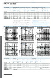
6. Performance charts Leistungskurven Courbes caractéristiques Curve caratteristiche 22<br />
7. Fan dimensions Ventilatorabmessungen Dimensions Dimensioni 36<br />
8. Accessories Zubehörteile Accessoires Accessori 45<br />
9. Specifications Ausschreibungstexte Spécifications téchniques Specifiche tecniche 50<br />
10. Rotation, discharge and<br />
accessories position<br />
Drehrichtung,<br />
Gehäusestellung, Position<br />
der Zubehörteile<br />
Sens de rotation,<br />
orientation de l’ouie<br />
d’aspiration et position des<br />
accessoires<br />
Senso di rotazione,<br />
orientamento della bocca<br />
premente e posizione<br />
degli accessori 58<br />
11. Reference code Typenchlüssel Codification Codifica 59<br />
1<br />
7
1. Standard <strong>TZAF</strong> <strong>FF</strong><br />
production range<br />
Comefri's <strong>TZAF</strong> <strong>FF</strong> doubleinlet-double-width<br />
centrifugal<br />
fans with Airfoil blades (AF)<br />
series cover a size range<br />
from 315 to 1250. All fans<br />
within the range have the<br />
following characteristics:<br />
• optimally engineered for<br />
HVAC applications;<br />
• high quality, compact design;<br />
• high efficiency, low power<br />
consumption;<br />
• quiet operation;<br />
• fan performances fully<br />
tested and certified in<br />
Comefri's own state-of-the-art<br />
laboratory in accordance with<br />
DIN, ISO, BS and AMCA<br />
standards;<br />
• Performance and Noise<br />
data according to DIN<br />
24166, accuracy Class 1.<br />
2. Technical details<br />
2.1. Forefinger ®<br />
It is an innovative device<br />
fully developed and<br />
engineered by the Aeraulic<br />
and Acoustic Test Lab of<br />
Comefri (*) (Fig.1). The<br />
principle is to exploit the air<br />
swirls, always present inside<br />
a fan housing. As well<br />
known, the recirculation of<br />
the air streams inside the<br />
fan housing is a major<br />
source of losses, decreasing<br />
the fan efficiency and<br />
increasing fan’s noise.<br />
This device, called<br />
Forefinger ® , is actively<br />
readdressing this air<br />
recirculation to the outlet,<br />
with a systematic<br />
enhancement of the<br />
performances, both aeraulic<br />
and acoustic.<br />
(*) Patent pending by Comefri<br />
1. Allgemeine<br />
Beschreibung der<br />
Baureihe <strong>TZAF</strong> <strong>FF</strong><br />
DOUBLE INLET AIRFOIL FANS – <strong>TZAF</strong> <strong>FF</strong><br />
ZWEISEITIGSAUGENDE AIRFOIL VENTILATOREN – <strong>TZAF</strong> <strong>FF</strong><br />
VENTILATEURS AIRFOIL DOUBLE ASPIRATION – <strong>TZAF</strong> <strong>FF</strong><br />
VENTILATORI AIRFOIL A DOPPIA ASPIRAZIONE – <strong>TZAF</strong> <strong>FF</strong><br />
Die zweiseitig saugende<br />
Comefri<br />
Radialventilatorbaureihe<br />
<strong>TZAF</strong> <strong>FF</strong> mit Airfoilschaufeln<br />
(AF) wird in den Baugrößen<br />
315 bis 1250 hergestellt.<br />
Alle Ventilatoren dieser<br />
Baureihe verfügen über<br />
folgende Eigenschaften:<br />
• Optimierte Kennlinie für die<br />
Klimatechnik;<br />
• Hohe Qualität, kompakte<br />
Bauweise;<br />
• Hohen Wirkungsgrad,<br />
niedrige Leistungsaufnahme;<br />
• Geräuscharmen Betrieb;<br />
• Leistungsdaten wurden im<br />
Comefri Labor nach<br />
DIN, ISO, BS, AMCA<br />
Standard gemessen;<br />
• Ventilatordaten nach DIN<br />
24166, Genauigkeitsklasse1<br />
2. Technische<br />
Eigenschaften<br />
2.1. Forefinger ®<br />
Es handelt sich um eine<br />
Innovation, entwickelt im<br />
Comefri eigenen Labor für<br />
Lufttechnik und Akustik. (*)<br />
(Bild 1). Die Hauptaufgabe<br />
besteht darin, die internen<br />
Verluste des Ventilators<br />
(im Gehäuse)<br />
zu reduzieren.<br />
Diese sind,<br />
wie allgemein<br />
bekannt, die<br />
wichtigste<br />
Ursache für<br />
Verluste eines<br />
Ventilators<br />
und<br />
beeinflussen<br />
den<br />
Wirkungsgrad<br />
negativ bei<br />
Fig.1<br />
Gleichzeitigem<br />
Anstieg des Lärmpegel.<br />
Mittels des neuen Patent<br />
Forefinger ® werden diese<br />
Verluste drastisch reduziert<br />
und somit die Leistungsdaten<br />
des Ventilators und auch die<br />
Akustik nachhaltig verbessert.<br />
(*) zum Patent angemeldet<br />
1. Généralités de la<br />
série <strong>TZAF</strong> <strong>FF</strong><br />
Les ventilateurs centrifuges<br />
double aspiration de la série<br />
<strong>TZAF</strong> <strong>FF</strong> ont les turbines<br />
avec aubes profilées (Airfoil)<br />
et sont const<strong>ru</strong>its de la taille<br />
315 à la taille 1250. Tous les<br />
ventilateurs de cette gamme<br />
ont les carac-téristiques<br />
suivantes:<br />
• particuliérement adaptes<br />
pour la climatisation;<br />
• niveau de qualité élevé,<br />
dimensions compactes;<br />
• niveau de rendement élevé,<br />
fiable puissance absorbée;<br />
• silencieux;<br />
• préstations garanties par<br />
d'essais effectués auprés du<br />
laboratoire Comefri, selon les<br />
normes DIN,ISO, BS et AMCA;<br />
• courbes obtenues selon les<br />
normes DIN 24166, Classe<br />
de précision 1.<br />
2. Caractéristique<br />
téchnique<br />
2.1. Forefinger ®<br />
Il s’agit d’un dispositif<br />
innovateur étudié et<br />
développé par le laboratoire<br />
aéraulique et acoustique de<br />
Comefri (*) (Fig.1). Son but est<br />
de mieux répartir et exploiter le<br />
circuit de la volute. En effet,<br />
comme nous le<br />
signalons, nous<br />
constatons que<br />
ce phénomène<br />
est la principale<br />
cause des<br />
pertes d’un<br />
ventilateur,<br />
ce qui<br />
conduit à un<br />
affaiblissement<br />
du rendement<br />
et une<br />
augmentation<br />
sensible du<br />
niveau sonore. Ce dispositif<br />
appelé Forefinger ® , agit<br />
activement sur le mouvement<br />
de l’air, ce qui d’une manière<br />
systématique permet<br />
d’accroître les performances<br />
aéraulique et acoustique.<br />
2<br />
(*) Titulaire de la relative<br />
demande du brevet<br />
1. Caratteristiche<br />
generali della serie<br />
<strong>TZAF</strong> <strong>FF</strong><br />
C-0075 December 2004<br />
I ventilatori centrifughi a<br />
doppia aspirazione della serie<br />
<strong>TZAF</strong> <strong>FF</strong> hanno le giranti con<br />
pale a profilo alare e sono<br />
cost<strong>ru</strong>iti nelle grandezze dalla<br />
315 alla 1250. Tutti i<br />
ventilatori compresi in questa<br />
gamma hanno le seguenti<br />
caratteristiche:<br />
• particolarmente adatti per la<br />
climatizzazione;<br />
• alta qualità, dimensioni<br />
compatte;<br />
• alto rendimento, bassa<br />
potenza assorbita;<br />
• silenziosità;<br />
• prestazioni garantite da<br />
prove eseguite presso il<br />
laboratorio Comefri, secondo le<br />
norme DIN, ISO, BS e AMCA;<br />
• curve caratteristiche ottenute<br />
secondo le norme DIN 24166,<br />
Classe di precisione 1.<br />
2. Caratteristiche<br />
tecniche<br />
2.1. Forefinger ®<br />
Si tratta di un dispositivo<br />
innovativo progettato e<br />
sviluppato dal Laboratorio<br />
Prove Aerauliche ed<br />
Acustiche della Comefri (*)<br />
(Fig.1). Il suo scopo è quello<br />
di ripartire e sf<strong>ru</strong>ttare i<br />
ricircoli d’aria presenti<br />
all’interno della coclea.<br />
Essi infatti, come noto,<br />
essendo la principale causa<br />
delle perdite di un<br />
ventilatore, ne condizionano<br />
negativamente il rendimento<br />
e ne aumentano<br />
sensibilmente la <strong>ru</strong>morosità.<br />
Il dispositivo, denominato<br />
Forefinger ® , di fatto è in<br />
grado di “intervenire<br />
attivamente” su tali ricircoli<br />
ai fini di un sistematico<br />
incremento delle prestazioni<br />
sia Aerauliche che<br />
Acustiche.<br />
(*) Titolare della relativa<br />
domanda di brevetto
DOUBLE INLET AIRFOIL FANS – <strong>TZAF</strong> <strong>FF</strong><br />
ZWEISEITIGSAUGENDE AIRFOIL VENTILATOREN – <strong>TZAF</strong> <strong>FF</strong><br />
VENTILATEURS AIRFOIL DOUBLE ASPIRATION – <strong>TZAF</strong> <strong>FF</strong><br />
VENTILATORI AIRFOIL A DOPPIA ASPIRAZIONE – <strong>TZAF</strong> <strong>FF</strong><br />
2.2. Housing 2.2. Gehäuse 2.2. Volute 2.2. Coclea<br />
All fan housings are<br />
manufactured in galvanised<br />
steel sheet (Fig.2) from size<br />
315 to 1000 and are<br />
const<strong>ru</strong>cted using the<br />
Pittsbourgh seam method<br />
(Fig.3), which ensures a high<br />
quality air tight seal as well<br />
as a st<strong>ru</strong>cturally reinforced<br />
housing. The design of the<br />
inlets is of vital importance<br />
for the fan performances<br />
Fig.2<br />
Fig.3<br />
and sound levels. They have<br />
been accurately engineered<br />
to guarantee an optimal<br />
airflow path towards the<br />
wheel and thus very high<br />
performance levels. The inlet<br />
cones are manufactured in<br />
sheet, steel as well, painted<br />
and bolted on the housing<br />
sideplates. A series of<br />
standard holes are located<br />
on the sideplates to allow the<br />
fitting of frames or feet.<br />
These holes are positioned<br />
in such a way that several<br />
standard accessories can be<br />
applied. Housings for sizes<br />
1120 and 1250 are<br />
manufactured in black steel<br />
sheet, reinforced with steel<br />
stiffeners, completely welded<br />
and painted with an<br />
anticorrosive epoxy paint.The<br />
inlet cones are also<br />
manufactured in black steel<br />
sheet, and painted. (Fig.4)<br />
Die Ventilatorgehäuse der<br />
Baugrößen 315 bis 1000,<br />
bestehen aus verzinktem<br />
Stahlblech (Bild 2);<br />
Seitenteile und<br />
Gehäusemantel sind durch<br />
den bewährten Pittsbourgh<br />
Falz miteinander verbunden<br />
(Bild 3), d.h. die vier<br />
übereinanderliegenden<br />
Materiallagen wirken<br />
versteifend.<br />
Die Einströmdüsen sind<br />
strömungsgünstig geformt<br />
und sorgen für eine optimale<br />
Beaufschlagung des<br />
Laufrades. Sie bestehen aus<br />
lackiertem Stahlblech und<br />
werden mit dem Gehäuse<br />
verschraubt.<br />
In den Gehäuseseitenteilen<br />
ermöglichen eingestanzte<br />
Löcher und Muttern eine<br />
einwandfreie Befestigung der<br />
Zubehörteile<br />
Die Gehäuse der Baugröße<br />
1120 und 1250 sind aus<br />
Stahlblech hergestellt,<br />
versteift, komplett<br />
geschweißt und lackiert. Die<br />
Einströmdüsen werden<br />
ebenfalls aus Stahlblech<br />
hergestellt und lackiert..<br />
(Bild 4)<br />
3<br />
Les volutes des ventilateurs<br />
de la taille 315 à la taille<br />
1000 sont const<strong>ru</strong>ites avec<br />
tôle d'acier galvanisé (Fig.2)<br />
et sont agrafées avec la<br />
méthode Pittsbourgh (Fig.3),<br />
qui assure qualité élevée,<br />
une parfaite étanchéité et<br />
une forte st<strong>ru</strong>cture.<br />
Etant donné que le profil du<br />
pavilion est d'importance<br />
fondamentale pour les<br />
Fig.4<br />
préstations des ventilateurs<br />
et pour leur b<strong>ru</strong>it, il a été<br />
étudié afin d'obtenir un flux<br />
d'air optimal et permettre par<br />
conséquence I'obtention d'un<br />
rendement tres élevé.<br />
Les pavilions sont const<strong>ru</strong>its<br />
en tôle d'acier peints et sont<br />
fixés aux fiasques de la<br />
volute.<br />
Une série des alésages<br />
standards est prédisposée<br />
sur les fiasques de façon à<br />
permettre le fixage des<br />
nombreux accessoires<br />
standards.<br />
Les volutes de la taille 1120<br />
et 1250 sont const<strong>ru</strong>ites en<br />
tôle noire d'acier, renforcée<br />
avec profilés soudés.<br />
Le tout est peint avec<br />
produits epox anticorrosion.<br />
(Fig.4)<br />
C-0075 December 2004<br />
Le coclee dei ventilatori dalla<br />
grandezza 315 alla 1000<br />
sono cost<strong>ru</strong>ite con lamiera<br />
d'acciaio zincato (Fig.2) e<br />
sono graffate con il metodo<br />
Pittsbourgh (Fig.3), il quale<br />
assicura alta qualità, perfetta<br />
tenuta e robustezza. Poichè<br />
il profilo del boccaglio di<br />
ingresso è di fondamentale<br />
importanza per le prestazioni<br />
dei ventilatori e per la loro<br />
<strong>ru</strong>morosità, esso è stato<br />
progettato in modo da<br />
garantire un flusso ottimale<br />
in aspirazione e di<br />
permettere quindi<br />
I'ottenimento di un<br />
rendimento molto elevato.<br />
I boccagli sono cost<strong>ru</strong>iti in<br />
lamiera d'acciaio, verniciati e<br />
sono fissati alle fiancate<br />
della coclea. Una serie di fori<br />
standard è predisposta sulle<br />
fiancate in modo da<br />
permettere il fissaggio dei<br />
telai. Altri fori permettono il<br />
fissaggio di numerosi<br />
accessori standard.<br />
Le coclee delle grandezze<br />
1120 e 1250 sono cost<strong>ru</strong>ite<br />
in lamiera nera d'acciaio,<br />
rinforzate da profilati saldati<br />
e verniciate con prodotti<br />
epox anticorrosione. (Fig.4)
2.3. Airfoil Impeller AF 2.3. Airfoil Laufrad<br />
(Hohlprofilschaufeln) AF<br />
This high performance<br />
impeller is manufactured in<br />
corrosion proof steel, with<br />
welded backward curved<br />
t<strong>ru</strong>e airfoil shaped blades,<br />
into position. All wheels are<br />
coated with epoxy paint<br />
(Fig. 5), balanced both<br />
statically and dynamically<br />
to an accuracy grade of<br />
G = 2.5 in accordance to<br />
DIN ISO 1940-1 (VDI 2060).<br />
The impellers are secured to<br />
the shaft through a steel or<br />
aluminium hub (aluminium is<br />
used from 315 B/R to 710<br />
B/R and from 315 T1 to 630<br />
T1). Hub bore is precision<br />
machined and incorporates a<br />
keyway and locking screw.<br />
DOUBLE INLET AIRFOIL FANS – <strong>TZAF</strong> <strong>FF</strong><br />
ZWEISEITIGSAUGENDE AIRFOIL VENTILATOREN – <strong>TZAF</strong> <strong>FF</strong><br />
VENTILATEURS AIRFOIL DOUBLE ASPIRATION – <strong>TZAF</strong> <strong>FF</strong><br />
VENTILATORI AIRFOIL A DOPPIA ASPIRAZIONE – <strong>TZAF</strong> <strong>FF</strong><br />
Die Hochleistungslaufräder<br />
AF sind aus hochwertigem,<br />
korrosionsbeständigem<br />
Stahl, mit geschweißten,<br />
rückwärtsgekrümmten<br />
Airfoilschaufeln hergestellt.<br />
Alle Laufräder sind mit<br />
Epoxlack beschichtet<br />
(Bild 5). Sie sind statisch und<br />
dynamisch in Gütestufe<br />
G=2,5 ausgewuchtet, gemäß<br />
DIN ISO 1940-1 (VDI 2060).<br />
Die Laufräder sind mit der<br />
Welle durch eine Stahl-bzw.<br />
Aluminiumnabe verbunden<br />
(Aluminiumnabe: Baugrößen<br />
315 bis 710 Ausfüh<strong>ru</strong>ngen B<br />
und R, Baugrößen 315 bis<br />
630 Ausfüh<strong>ru</strong>ng T1).<br />
Die Nabenboh<strong>ru</strong>ngen sind<br />
mit einer Passfedernut und<br />
einer Befestigungsschraube<br />
ausgerüstet.<br />
Fig.5<br />
2.3. Turbine avec aubes<br />
profilées (Airfoil)<br />
Ces turbines à rendement<br />
élevé sont const<strong>ru</strong>ites en<br />
acier résistant à la corrosion<br />
et ont les aubes soudées<br />
courbées vers I'arriére à<br />
profilees (Airfoil). Toutes les<br />
turbines sont revêtues d'une<br />
couche de peinture epox<br />
(Fig.5). Elles sont equilibrées<br />
statiquement et<br />
dynamiquement avec un<br />
degré de tolérance G=2,5<br />
selon les normes<br />
DIN ISO 1940-1 (VDI 2060).<br />
Les turbines sont fixées a<br />
I'arbre à I'aide de moyeux<br />
munis de clavette et vis de<br />
blocage. Les moyeux sont<br />
en aluminium pour les<br />
modéles du 315 B/R au 710<br />
B/R et du 315 T1 au 630 T1.<br />
Pour les autres modéles sont<br />
en acier.<br />
2.4. Shafts 2.4. Wellen 2.4. Arbres 2.4. Alberi<br />
All shafts are designed with<br />
a high safety factor and with<br />
the first critical speed well<br />
beyond to the maximum fan<br />
speed.<br />
Made in hardened steel, they<br />
are precision ground and<br />
polished.<br />
Shafts are provided with<br />
keyways for the wheel hub<br />
and for belt pulleys that can<br />
be fitted on either shaft ends.<br />
All shafts are coated with<br />
protective paint for added<br />
protection prior to shipping.<br />
Alle Wellen sind mit einem<br />
hohen Sicherheitsfaktor<br />
berechnet. Dabei liegt die<br />
maximal zulässige<br />
Drehzahl weit unter der<br />
ersten kritischen Drehzahl.<br />
Die geschliffenen Wellen<br />
sind aus hochwertigem<br />
Stahl hergestellt.<br />
Die Verbindung von<br />
Laufrad/Welle und<br />
Keilriemenscheibe/Welle<br />
erfolgt mittels Nut und Feder.<br />
Alle Wellen werden mit<br />
Rostschutzlack geschützt.<br />
4<br />
Tous les arbres sont<br />
dimensionnés avec un<br />
coefficient de sécurité élevé.<br />
La vitesse maximale admise<br />
est bien inférieure à la vitesse<br />
critique. Ils sont const<strong>ru</strong>its en<br />
acier au carbone, usinés et<br />
réctifiés. Les arbres ont une<br />
clavette en correspondence<br />
au moyeu de la turbine et<br />
une autre clavette à chaque<br />
extémité, de façon que la<br />
poulie puisse être montée<br />
indifféremment d'une côté ou<br />
de I'autre. Tous les arbres<br />
sont couverts avec une<br />
peinture protective.<br />
2.3. Girante con pale a<br />
profilo alare<br />
C-0075 December 2004<br />
Queste giranti ad alto<br />
rendimento sono cost<strong>ru</strong>ite in<br />
acciaio resistente alla<br />
corrosione, con pale saldate<br />
curvate all'indietro a profilo<br />
alare e verniciate con smalto<br />
epox (Fig.5).<br />
Esse sono bilanciate<br />
staticamente e<br />
dinamicamente<br />
con un grado tolleranza<br />
G = 2,5 secondo le norme<br />
DIN ISO 1940-1 (VDI 2060).<br />
Le giranti sono calettate<br />
all'albero tramite mozzi<br />
muniti di linguetta e vite di<br />
serraggio.<br />
I mozzi sono in alluminio nei<br />
modelli dal 315 B/R al<br />
710 B/R e dal 315 T1 al<br />
630 T1. Negli altri modelli<br />
sono in acciaio.<br />
Tutti gli alberi sono<br />
dimensionati con un elevato<br />
coefficiente di sicurezza ed<br />
una velocità critica<br />
largamente superiore alla<br />
massima velocità di<br />
funzionamento consentita.<br />
Sono cost<strong>ru</strong>iti in acciaio al<br />
carbonio, torniti e rettificati.<br />
Gli alberi hanno<br />
una sede linguetta in<br />
corrispondenza del mozzo<br />
della girante ed un'altra ad<br />
ogni estremità.<br />
Tutti gli alberi sono rivestiti<br />
con una vernice protettiva.
DOUBLE INLET AIRFOIL FANS – <strong>TZAF</strong> <strong>FF</strong><br />
ZWEISEITIGSAUGENDE AIRFOIL VENTILATOREN – <strong>TZAF</strong> <strong>FF</strong><br />
VENTILATEURS AIRFOIL DOUBLE ASPIRATION – <strong>TZAF</strong> <strong>FF</strong><br />
VENTILATORI AIRFOIL A DOPPIA ASPIRAZIONE – <strong>TZAF</strong> <strong>FF</strong><br />
2.5. Bearings 2.5. Lager 2.5. Paliers 2.5. Cuscinetti<br />
From sizes 315 B/R to 710<br />
B/R, from 400 T2L to 1000<br />
T2L, from 315 T1 to 1120 T1<br />
and from size 355 T2 to 500<br />
T2, bearings are selfaligning,<br />
single row, deep<br />
groove, ball type, with<br />
eccentric locking ring. Sizes<br />
560 T2 and 630 T2 have<br />
double row ball bearings in<br />
pillow block splitted cast iron<br />
housings.<br />
Size 1250 T1 and sizes from<br />
710 T2 to 1250 T2 have<br />
double row roller bearings in<br />
pillow block splitted cast iron<br />
housings.<br />
B/R and T2L from sizes 400<br />
to 500 versions have the<br />
bearings mounted in a<br />
<strong>ru</strong>bber ring, which is fit in a<br />
three-arm or four-arm spider<br />
bracket (Fig. 6). These<br />
bearings are tight and lifelubricated.<br />
T1, T2L from 560 to 1000<br />
and T2 fans have the pillow<br />
block bearings mounted on<br />
steel profiles welded on the<br />
T frame (Fig. 7, 8).<br />
These bearings are<br />
equipped with grease<br />
nippels.<br />
All bearings have been<br />
selected to guarantee a<br />
minimum L 10 life of 20.000<br />
hours. For size 1120 T1 and<br />
from size 710 T2 to size<br />
1250 T2 the minimum<br />
guaranteed life is 40.000<br />
hours operating at maximum<br />
speed.<br />
Fig.6<br />
Von der Baugröße 315 B/R<br />
bis 710 B/R, von 400 T2L<br />
bis 1000 T2L, von 315 T1 bis<br />
1120 T1 und von 355 T2 bis<br />
500 T2, sind die Ventilatoren<br />
mit selbsteinstellenden<br />
Rillen-Kugellagern und<br />
einem exzentrischem<br />
Spannring ausgerüstet. Die<br />
Baugrößen 560 T2 , 630 T2<br />
sind mit GußPendelkugellager<br />
ausgerüstet.<br />
Die Baugröße 1250 T1 und<br />
die Baugrößen von 710 T2<br />
bis 1250 T2 sind mit Guß-<br />
Pendelrollenlager<br />
ausgerüstet. Die Lager der<br />
B/R und T2L-Ausfüh<strong>ru</strong>ng<br />
vom Baugröße 400 bis 500<br />
sind in einem<br />
Gummidämmring und einem<br />
3- bzw. 4- armigen<br />
Lagerkreuz gelagert. Diese<br />
Lager sind<br />
lebensdauergeschmiert und<br />
optimal abgedichtet (Bild 6).<br />
Ventilatoren in den<br />
Ausfüh<strong>ru</strong>ngen T1, T2L vom<br />
Baugröße 560 bis 1000 und<br />
T2 haben Gußstehlager auf<br />
geschweißten T-Rahmen<br />
montiert (Bild 7, 8). Diese<br />
Lager sind mit Schmiernippel<br />
ausgerüstet.<br />
Alle Lager sind für eine<br />
minimale Lebensdauer von<br />
L 10 20.000 Stunden<br />
ausgelegt. Die Lager der<br />
Baugröße 1120 T1 und von<br />
710 T2 bis 1250 T2 sind für<br />
L 10 40.000 Stunden bei<br />
maximaler Drehzahl<br />
dimensioniert.<br />
Fig.7<br />
5<br />
De la taille 315 B/R à la taille<br />
710 B/R,de la 400 T2L à la<br />
1000 T2L, de la 315 T1 à la<br />
1120 T1 et de la taille 355<br />
T2 à la taille 500 T2 , les<br />
supports sont auto-alignants<br />
et sont équippés avec<br />
paliers à une couronne de<br />
billes, munis de collier<br />
excentrique de serrage.<br />
Sur les tailles 560 T2 et 630<br />
T2 les supports sont en fonte<br />
en deux parties avec paliers<br />
orientables a double couronne<br />
de billes. Les tailles 1250 T1,<br />
et de la 710 T2 à la 1250 T2<br />
ont les supports en fonte en<br />
deux parties avec paliers<br />
orientables à double<br />
couronne de rouleaux.<br />
Sur la version B/R et T2L de<br />
la taille 400 à la 500 les<br />
paliers sont à parfaite<br />
étanchéité et lubrifiés a vie,<br />
inserés dans un manchon en<br />
gomme soutenu par un<br />
croisillon en acier (Fig.6).<br />
Sur la version T1, T2L de la<br />
taille 560 à la 1000 et T2 les<br />
supports sont montés sur<br />
des profils en acier soudés<br />
au cadre de support T<br />
(Fig.7, 8). Ils sont munis de<br />
graisseurs pour la<br />
relubrification des paliers.<br />
Les paliers ont été<br />
dimensionnés pour garantir<br />
une durée minimale L10 de<br />
20.000 heures. Pour la taille<br />
1120 T1 et de la taille 710<br />
T2 à la taille 1250 T2 la<br />
durée de vie min. garantie<br />
est de 40.000 heures avec<br />
fonctionnement à la vitesse<br />
maximale<br />
Fig.8<br />
C-0075 December 2004<br />
Dalla grandezza 315 B/R<br />
alla 710 B/R, dalla 400 T2L<br />
alla 1000 T2L, dalla 315 T1<br />
alla 1120 T1 e dalla<br />
grandezza 355 T2 alla 500<br />
T2, i supporti sono<br />
autoallineanti e contengono<br />
cuscinetti ad una corona di<br />
sfere, muniti di collare<br />
eccentrico di fissaggio.<br />
Sulle grandezze 560 T2 e<br />
630 T2, i supporti sono in<br />
ghisa in due metà con<br />
cuscinetti orientabili a doppia<br />
corona di sfere.<br />
Le grandezze 1250 T1 ed i<br />
ventilatori dalla taglia 710 T2<br />
alla 1250 T2 hanno i supporti<br />
in ghisa in due metà con<br />
cuscinetti orientabili a doppia<br />
corona di <strong>ru</strong>lli. Nella versione<br />
B/R e T2L dalla grandezza<br />
400 alla 500 i cuscinetti sono<br />
a tenuta stagna e lubrificati a<br />
vita, alloggiati in un anello<br />
smorzatore in gomma<br />
sostenuto da una raggiera a<br />
tre o quattro bracci in acciaio<br />
(Fig.6). Nella versione T1,<br />
T2L dalla grandezza 560<br />
alla 1000 e T2 i supporti<br />
sono montati su profilati in<br />
acciaio saldati al telaio T<br />
(Fig.7, 8). Essi sono muniti di<br />
ingrassatori per la<br />
rilubrificazione dei cuscinetti.<br />
I cuscinetti sono stati<br />
dimensionati per garantire<br />
una durata minima L10 di<br />
20.000 ore. Per le grandezze<br />
dal 1120 T1 e dal 710 T2 al<br />
1250 T2 la durata minima<br />
garantita è di 40.000 ore con<br />
funzionamento alla velocità<br />
massima.
DOUBLE INLET AIRFOIL FANS – <strong>TZAF</strong> <strong>FF</strong><br />
ZWEISEITIGSAUGENDE AIRFOIL VENTILATOREN – <strong>TZAF</strong> <strong>FF</strong><br />
VENTILATEURS AIRFOIL DOUBLE ASPIRATION – <strong>TZAF</strong> <strong>FF</strong><br />
VENTILATORI AIRFOIL A DOPPIA ASPIRAZIONE – <strong>TZAF</strong> <strong>FF</strong><br />
2.6. Frames 2.6. Rahmen 2.6. Cadres de support 2.6. Telai<br />
The fan must be stabilised<br />
on a base (frame or platform)<br />
to ensure no st<strong>ru</strong>ctural<br />
deformations caused by the<br />
tension of the belts.<br />
This concerns<br />
especially fans in discharge<br />
position 270°.<br />
Therefore we recommend<br />
the use of the R-frame<br />
execution or a similar<br />
reinforced st<strong>ru</strong>cture when the<br />
fan works at the limits of its<br />
performances.<br />
This will increase the life<br />
time of the fan.<br />
3. Labelling of fan<br />
components<br />
1<br />
Der Ventilator ist<br />
g<strong>ru</strong>ndsätzlich so auf einem<br />
G<strong>ru</strong>ndrahmen, bzw. einer<br />
G<strong>ru</strong>ndplatte zu fixieren, dass<br />
keine Deformation durch<br />
den Riemenzug entstehen<br />
kann. Wir empfehlen, bei<br />
Ventilatoren in B-Ausfüh<strong>ru</strong>ng<br />
an der oberen<br />
Leistungsgrenze, die<br />
Verwendung eines R-<br />
Rahmens oder eine ähnliche<br />
Ausfüh<strong>ru</strong>ng vorzusehen.<br />
Diese Maßnahme kann die<br />
Lebensdauer der<br />
Ventilatorkugellager deutlich<br />
erhöhen.<br />
3. Bezeichnung der<br />
Ventilatorbauteile<br />
- INLET GUARD / ANSAUGSCHUTZGITTER /<br />
PROTECTION A I'ASPIRATION / RETE DI PROTEZIONE ASPIRANTE<br />
5<br />
Les ventilateurs doivent être<br />
fixés sur un chassis de façon<br />
à éviter déformations<br />
causées par la tension des<br />
courroies.<br />
Celà est particulièrement<br />
critique avec I'orientation<br />
270°. Nous conseillons par<br />
conséquence I'utilisation de<br />
la version avec cadre R ou<br />
d'une st<strong>ru</strong>cture renforcée de<br />
la même façon, quand le<br />
ventilateur fonctionne à la<br />
limite de ses préstations.<br />
Ce fait augmente la durée du<br />
ventilateur.<br />
C-0075 December 2004<br />
I ventilatori devono essere<br />
fissati su di un telaio di base<br />
in modo da evitare<br />
deformazioni causate dal tiro<br />
cinghia.<br />
Questo è particolarmente<br />
critico nell'orientamento a<br />
270°. Raccomandiamo<br />
quindi I'uso della versione<br />
con telaio R o di una<br />
st<strong>ru</strong>ttura similmente<br />
rinforzata, quando il<br />
ventilatore lavora al limite<br />
delle sue prestazioni.<br />
Questo aumenta la durata<br />
del ventilatore.<br />
3. Liste des composants 3. Elenco dei componenti<br />
- DRAIN PLUG / KONDENSATABLAUFSTUTZEN /<br />
PURGE SUR VOLUTE / TAPPO DI SCARICO<br />
2 - T FRAME / “T” RAHMEN / CADRE TYPE T / TELAIO TIPO T 6 - MOTOR / MOTOR / MOTEUR / MOTORE ELETTRICO 29<br />
3<br />
4<br />
- INLET CONE WITH FOREFINGER / EINSTRÖMDÜSE MIT FOREFINGER /<br />
PAVILION AVEC FOREFINGER / BOCCAGLIO CON FOREFINGER<br />
- INSPECTION DOOR / INSPEKTIONSKLAPPE /<br />
PORTE D'INSPECTION / PORTINA D'ISPEZIONE<br />
7<br />
- MOTOR RAILS / MOTORSPANNSCHIENEN /<br />
RAILS TENDEUR, GLISSIERES / SLITTE TENDICINGHIA<br />
8 - BASE FRAME / GRUNDRAHMEN / CHASSIS / BASAMENTO 31<br />
6<br />
9<br />
10<br />
11<br />
- ANTIVIBRATION MOUNTING / SCHWINGUNGSDÄMPFER /<br />
SUPPORTS ANTIVIBRATILES / SUPPORTI ANTIVIBRANTI<br />
- FAN PULLEY / KEILRIEMENSCHEIBE /<br />
POULIE VENTILATEUR / PULEGGIA VENTILATORE<br />
- BELT GUARD / RIEMENSCHUTZGITTER /<br />
CARTER DE PROTECTION TRANSMISSION /<br />
CARTER DI PROTEZIONE TRASMISSIONE<br />
12 - BELTS / KEILRIEMEN / COURROIES / CINGHIE<br />
13<br />
14<br />
15<br />
16<br />
17<br />
- OUTLET FLEXIBLE CONNECTION / ELASTISCHER DRUCKFLANSCH /<br />
MANCHETTE SOUPLE AU REFOULEMENT /<br />
GIUNTO ANTIVIBRANTE PREMENTE<br />
- OUTLET GUARD / AUSBLASSCHUTZ / PROTECTION<br />
AU REFOULEMENT / RETE DI PROTEZIONE PREMENTE<br />
- OUTLET COUNTERFLANGE / GEGENFLANSCH /<br />
CONTREBRIDE AU REFOULEMENT / CONTROFLANGIA PREMENTE<br />
- BEARING SUPPORT / LAGER AUFNAHME /<br />
SUPPORT PALIER / SUPPORTO CUSCINETTO<br />
- SHAFT GUARD / WELLENSCHUTZGITTER / CARTER DE<br />
PROTECTION DE L’ARBRE / CARTER DI PROTEZIONE ALBERO<br />
18 - WHEEL / LAUFRAD / TURBINE / GIRANTE<br />
19 - HOUSING / VENTILATORGEHÄUSE / VOLUTE / COCLEA<br />
20 - SHAFT / SWELLE / ARBRE / ALBERO<br />
21 - CUT O<strong>FF</strong> / LEITBLECH / DÉFLECTEUR / DEFLETTORE<br />
22 - R FRAME / “R” RAHMEN / CADRE TYPE R / TELAIO TIPO R<br />
23<br />
24<br />
25<br />
- BEARING BRACKET / LAGERKREUZ /<br />
BRAS DE SUPPORT / RAGGIERA<br />
- GUARD MOUNT / BEFESTIGUNGSSTÜTZE /<br />
SUPPORTS CARTER / SOSTEGNI CARTER<br />
- MOTOR PULLEY / KEILRIEMENSCHEIBE /<br />
POULIE MOTEUR / PULEGGIA MOTORE<br />
26 - HUB / NABE / MOYEU / MOZZO<br />
27 - FEET / FÜSSE / PIEDS / PIEDI<br />
28 - BEARING / LAGER / PALIER / CUSCINETTO<br />
30<br />
- RUBBER INTERLINER / GUMMIDÄMMRING /<br />
BAGUE CAOUTCHOUC / MANICOTTO IN GOMMA<br />
- OUTLET FLANGE / DRUCKFLANSCH /<br />
BRIDE AU REFOULEMENT / FLANGIA PREMENTE<br />
- MOTOR BASE PLATE / MOTORSPANNSCHLITTEN /<br />
SUPPORT MOTEUR / BASE MOTORE
4. Fan performances 4. Ventilator<br />
Listungskurven<br />
DOUBLE INLET AIRFOIL FANS – <strong>TZAF</strong> <strong>FF</strong><br />
ZWEISEITIGSAUGENDE AIRFOIL VENTILATOREN – <strong>TZAF</strong> <strong>FF</strong><br />
VENTILATEURS AIRFOIL DOUBLE ASPIRATION – <strong>TZAF</strong> <strong>FF</strong><br />
VENTILATORI AIRFOIL A DOPPIA ASPIRAZIONE – <strong>TZAF</strong> <strong>FF</strong><br />
4. Prestations 4. Prestazioni<br />
4.1. Performance data 4.1. Leistungsdaten 4.1. Diagrammes 4.1. Diagrammi<br />
Comefri’s laboratory has<br />
measured the data included<br />
in the performance chart<br />
section with modern, stateof-the-art<br />
testing<br />
inst<strong>ru</strong>ments.<br />
• The performances were<br />
measured for an installation<br />
type B, i.e. free inlet and<br />
ducted outlet configuration<br />
• All curves to a density of<br />
ρ = 1,2 kg/m 3<br />
• Outlet velocity “c” and<br />
dynamic pressure “pdyn“refer<br />
to the flange cross section<br />
area at the fan outlet<br />
• The performance data<br />
tolerances are according to<br />
DIN 24166 Class 1.<br />
Performance test rig<br />
according to DIN 24163 /<br />
BS 848 Part 1 / ISO 5801 /<br />
AMCA 210 - fig.14.<br />
1. Fan<br />
2. Outlet duct<br />
3. Electric motor drive<br />
4. Torquemeter<br />
5. Tachometer<br />
6. Differential pressure gauge<br />
7. Temperature probe<br />
8. Test chamber<br />
9. Flow straightener<br />
10. Damper<br />
11. Normalized inlet<br />
The performance curves inclu-<br />
de the following information:<br />
Im Comefri-Labor wurden die<br />
Leistungsdaten mit<br />
modernster Technik<br />
aufgenommen.<br />
• Die Ermittlung der<br />
Kennlinien erfolgte mit<br />
d<strong>ru</strong>ckseitigem<br />
Kanalanschluss<br />
freiansaugend<br />
• Alle Leistungsdiagramme<br />
beziehen sich auf eine<br />
Luftdichte von ρ = 1,2 kg/m 3<br />
• Die Ausblasgeschwindigkeit<br />
“c“ und der dynamische<br />
D<strong>ru</strong>ck “pdyn“beziehen sich auf<br />
den Ausblasflanschquerschnitt<br />
• Leistungsdaten nach<br />
DIN 24166 in<br />
Genauigkeitsklasse 1.<br />
Prüfstandaufbau nach<br />
DIN 24163/ BS 848 Part 1 /<br />
ISO 5801 / AMCA 210 - fig.14.<br />
1. Ventilator<br />
2. Ausblaskanal<br />
3. Elektrischer Antrieb<br />
4. Drehmomentaufnehmer<br />
5. Drehzahlmesser<br />
6. Differenzd<strong>ru</strong>ckmesser<br />
7. Temperaturaufnahme<br />
8. Prüfkammer<br />
9. Strömungsgleichrichter<br />
10. Drossel<br />
11. Einlauf-Normdüse<br />
Die Leistungskurven zeigen<br />
folgende Informationen:<br />
Les données représentées<br />
sur les courbes de sélection<br />
ont été élaborées avec des<br />
mésure effectuées selon les<br />
plus modernes méthodologies<br />
dans le Laboratoire Comefri.<br />
• Les préstations font<br />
réference à une installation<br />
de type B, avec aspirations<br />
libres et refoulement<br />
canalisé<br />
• Toutes les courbes font<br />
reference a une densite d'air<br />
de ρ = 1,2 kg/m 3<br />
• La vitesse de sortie “c” et la<br />
pression dynamique “pdyn”<br />
font réference à la section de<br />
la bride du refoulement<br />
• Les tolérances appliquées<br />
aux mésurations suivent les<br />
normes DIN 24166 Classe 1<br />
Schéma banc d'essai selon<br />
les normes DIN 24163 /<br />
BS 848 Part 1 / ISO 5801 /<br />
AMCA 210 - fig.14.<br />
1. Ventilateur<br />
2. Canal de refoulement<br />
3. Moteur éléctrique<br />
4. Torsiomètre<br />
5. Tachymètre<br />
6. Manomètre différentiel<br />
7. Sonde thermométrique<br />
8. Salle d'essai<br />
9. Redresseur de flux<br />
10. Registre de réglage<br />
11. Pavillon normalisé<br />
Les diagrammes comprennent<br />
les données suivantes:<br />
C-0075 December 2004<br />
I dati riportati nelle curve di<br />
selezione sono stati ricavati<br />
da misure eseguite con le<br />
più moderne metodologie nel<br />
laboratorio Comefri.<br />
• Le prestazioni sono riferite<br />
ad un'installazione di tipo B,<br />
con bocche aspiranti libere e<br />
bocca di mandata canalizzata<br />
• Tutte le curve sono riferite<br />
ad una densità dell'aria di<br />
ρ = 1,2 kg/m 3<br />
• La velocità di uscita “c” e la<br />
pressione dinamica “pdyn”<br />
sono riferite alla sezione<br />
della flangia della bocca<br />
premente<br />
• Le tolleranze applicate alle<br />
misurazioni sono secondo le<br />
norme DIN 24166, Classe 1<br />
Schema banco prova<br />
secondo le norme<br />
DIN 24163 / BS 848 Part 1 /<br />
ISO 5801 / AMCA 210 - fig.14.<br />
1. Ventilatore<br />
2. Canale di mandata<br />
3. Motore elettrico<br />
4. Torsiometro<br />
5. Tachimetro<br />
6. Manometro differenziale<br />
7. Sonda termometrica<br />
8. Camera di prova<br />
9. Raddrizzatore di flusso<br />
10. Serranda di regolazione<br />
11. Boccaglio normalizzato<br />
I diagrammi comprendono i<br />
dati seguenti:<br />
Total pressure Gesamtd<strong>ru</strong>ckdifferenz Pression totale Pressione totale ∆ptot [ Pa ]<br />
Dynamic pressure Dynamischer D<strong>ru</strong>ck Pression dynamique Pressione dinamica pdyn [ Pa ]<br />
Volume air flow Volumenstrom Débit Portata V ° [ m 3 /h ]<br />
Absorbed power on fan<br />
shaft<br />
Aufgenommene Leistung an<br />
der Welle<br />
Puissance absorbée à l'arbre du<br />
ventilateur<br />
Potenza assorbita all'albero del<br />
ventilatore<br />
Fan speed Ventilatordrehzahl Vitesse de rotation du ventilateur Velocità di rotazione del ventilatore n [ min -1 ]<br />
Total Efficiency Gesamtwirkungsgrad Rendement totat Rendimento totate ηt [ % ]<br />
Outlet velocity Ausblasgeschwindigkeit Vitesse de sortie de I’air Velocità di uscita dell'aria c [ m/s ]<br />
Sound Power Level Schalleistungspegel Niveau de puissance sonore Livello di Potenza Sonora LwA4/7 [ dB(A) ]<br />
7<br />
Pw<br />
[ kW ]
4.2.1 Efficiency correction 4.2.1 Korrektur des<br />
Wirkungsgrades<br />
The efficiencies marked in<br />
the performance graph<br />
charts are valid at the<br />
maximum permissible<br />
rotation speed, nmax; they<br />
decrease when fan speed<br />
decreases. To obtain the<br />
correct efficiency value,<br />
multiply the read value by a<br />
corrective factor Kη for the<br />
chosen fan speed and<br />
different fan configuration<br />
(B, R, T1, T2L from 400 to<br />
1000 and T2). The factor<br />
Kη can be read off the<br />
horizontal scales, in the<br />
bottom of each performance<br />
graph charts, as a function<br />
of the fan speed “n” and fan<br />
version.<br />
DOUBLE INLET AIRFOIL FANS – <strong>TZAF</strong> <strong>FF</strong><br />
ZWEISEITIGSAUGENDE AIRFOIL VENTILATOREN – <strong>TZAF</strong> <strong>FF</strong><br />
VENTILATEURS AIRFOIL DOUBLE ASPIRATION – <strong>TZAF</strong> <strong>FF</strong><br />
VENTILATORI AIRFOIL A DOPPIA ASPIRAZIONE – <strong>TZAF</strong> <strong>FF</strong><br />
Die in den Kennfeldern<br />
angegebenen<br />
Wirkungsgrade beziehen<br />
sich auf maximale Drehzahl<br />
des Ventilators. Bei<br />
geringerer Drehzahl müssen<br />
die Werte korrigiert werden.<br />
Dies geschieht indem der<br />
über den Wirkungsgradlinien<br />
angegeben Wert mit einem<br />
Korrekturfaktor Kη<br />
multipliziert wird. Der Wert<br />
für Kh ist abhängig von der<br />
Ausfüh<strong>ru</strong>ng (B, R, T1, T2L<br />
von 400 bis 1000 und T2)<br />
des Ventilators und kann<br />
unter den Kennfeldern in den<br />
dort befindlichen Diagrammen<br />
in Abhängigkeit von<br />
Drehzahl und Ausfüh<strong>ru</strong>ng<br />
entnommen werden.<br />
4.2.1 Correction du<br />
rendement<br />
Les valeurs de rendement<br />
indiquées sur les courbes de<br />
sélection se réfèrent à la<br />
vitesse de fonctionnement la<br />
plus grande. Compte-tenu<br />
que le rendement diminue en<br />
fonction de la baisse de la<br />
vitesse, la valeur inscrite sur<br />
la courbe devra être corrigé<br />
par un coefficient Kη<br />
(différent selon le type du<br />
ventilateur : B, R, T1, T2L<br />
de 400 à 1000 ou T2)<br />
en fonction de la vitesse de<br />
rotation sélectionnée et de la<br />
configuration du ventilateur.<br />
Les valeurs de ce coefficient<br />
se trouvent sur un abaque<br />
rapporté sous la courbe de<br />
sélection.<br />
4.2.2 Operation area 4.2.2 Einsatzbereich 4.2.2 Zone de<br />
fonctionnement<br />
Area-1 in the graphs ( where<br />
the performance curves are<br />
dashed) identifies the area in<br />
which the presence of inlet<br />
obst<strong>ru</strong>ctions (like pulleys,<br />
etc) could generate an<br />
instability in the fan<br />
operation. This phenomena<br />
is more important for the<br />
medium - big fan sizes, at<br />
high speed.<br />
The selection of a fan on the<br />
left of Area-1 always leads to<br />
instability problems,<br />
regardless of the presence<br />
at the inlet of disturbing<br />
elements in the airstream.<br />
Therefore, only a fan<br />
selection inside the Area-2 is<br />
guarantee of smooth and<br />
trouble-free operation, with<br />
maximum efficiency and<br />
minimized acoustic<br />
emissions.<br />
Area-1 (im schrafiertem<br />
Bereich) kennzeichnet den<br />
Bereich, in dem aufg<strong>ru</strong>nd<br />
von vor der Ansaugöffnung<br />
befindlichen Einbauten<br />
(Riemenscheibe,<br />
Schutzvorrichtungen, usw.)<br />
mit der Entstehung von<br />
Turbulenzen zu rechnen ist,<br />
die ein instabiles Arbeiten<br />
des Ventilators ve<strong>ru</strong>rsachen.<br />
Dieses Phänomen tritt vor<br />
allem bei mittleren bis<br />
großen Ventilatoren und bei<br />
hohen Drehzahlen auf. Der<br />
Einsatz eines Ventilators im<br />
linken Bereich von Area-1<br />
führt, unabhängig von der<br />
Einbausituation und<br />
vorgeschalteter,<br />
strömungsbeeinflussender<br />
Einbauten, fast immer zu<br />
einem instabilen Betrieb des<br />
Ventilators. Der Einsatz des<br />
Ventilators in Area-2<br />
garantiert hingegen eine<br />
stö<strong>ru</strong>ngsfreie Strömung und<br />
damit maximalen<br />
Wirkungsgrad und minimale<br />
Schallemission.<br />
8<br />
La zone 1 du graphique<br />
(partie délimitée sur la<br />
courbe de sélection) définit<br />
une zone de travail du<br />
ventilateur dans laquelle la<br />
présence d’une poulie ou de<br />
tout autres éléments<br />
disposés dans l’ouie<br />
d’aspiration peuvent<br />
entraîner une instabilité dans<br />
le fonctionnement;<br />
phénomène encore plus<br />
accentué principalement sur<br />
les ventilateurs de moyenne<br />
et grande taille lorsqu’ils sont<br />
utilisés à des vitesses<br />
importantes. La zone 1 définit<br />
également la limite de<br />
représentation de la courbe<br />
caractéristique de<br />
fonctionnement. A gauche de<br />
la zone 1, le comportement<br />
des ventilateurs centrifuges<br />
reste toujours instable,<br />
indépendamment de la<br />
présence ou non d’éléments<br />
perturbant l’aspiration. C’est<br />
pour cette raison que<br />
seulement le choix d’un<br />
ventilateur dans la zone 2,<br />
qui garantit des<br />
caractéristiques de<br />
fonctionnement avec un<br />
meilleur rendement et une<br />
plus faible émission<br />
acoustique.<br />
4.2.1 Correzione del<br />
rendimento<br />
C-0075 December 2004<br />
I valori di rendimento indicati<br />
sulle curve di selezione sono<br />
riferiti alla velocità massima<br />
di funzionamento. Poichè il<br />
rendimento diminuisce col<br />
diminuire della velocità, il<br />
valore letto sul diagramma<br />
dovrà essere corretto con un<br />
fattore Kη (diverso a<br />
seconda della tipologia di<br />
ventilatore: B, R, T1,<br />
T2L dal 400 al 1000 e T2) in<br />
funzione, sia della velocità<br />
di rotazione scelta, che della<br />
configurazione del<br />
ventilatore. I valori di Kη si<br />
possono ricavare dalle scale<br />
orizzontali riportate nelle<br />
curve di selezione.<br />
4.2.2 Area di<br />
funzionamento<br />
L’Area-1 dei grafici (area in<br />
cui le curve di prestazione<br />
sono rappresentate<br />
tratteggiate) identifica quella<br />
particolare zona di lavoro del<br />
ventilatore dove la presenza<br />
di una puleggia, o di un<br />
qualunque altro elemento<br />
all’aspirazione, potrebbe<br />
comportare l’insorgere di<br />
instabilità di funzionamento;<br />
fenomeno rilevante<br />
specialmente su ventilatori<br />
medio-grandi quando<br />
utilizzati ad un elevato<br />
numero di giri. L’Area-1, allo<br />
stesso tempo, definisce il<br />
limite di rappresentazione<br />
delle curve caratteristiche di<br />
funzionamento. A sinistra<br />
dell’Area-1, il<br />
comportamento dei<br />
ventilatori centrifughi risulta<br />
essere sempre instabile,<br />
indipendentemente dalla<br />
presenza o meno di elementi<br />
che ne influenzino<br />
l’aspirazione. Perciò, la sola<br />
scelta di un ventilatore<br />
eseguita tramite selezione<br />
all’interno dell’Area-2, è<br />
garanzia di un<br />
funzionamento con<br />
caratteristiche di massimo<br />
rendimento e minime<br />
emissioni acustiche.
DOUBLE INLET AIRFOIL FANS – <strong>TZAF</strong> <strong>FF</strong><br />
ZWEISEITIGSAUGENDE AIRFOIL VENTILATOREN – <strong>TZAF</strong> <strong>FF</strong><br />
VENTILATEURS AIRFOIL DOUBLE ASPIRATION – <strong>TZAF</strong> <strong>FF</strong><br />
VENTILATORI AIRFOIL A DOPPIA ASPIRAZIONE – <strong>TZAF</strong> <strong>FF</strong><br />
4.3. Motor selection 4.3. Motorauslegung 4.3. Selection du moteur 4.3. Scelta del motore<br />
To determine the minimum<br />
motor power PM, the fan<br />
absorbed shaft power PW<br />
must be increased by a<br />
factor fW to accommodate<br />
for the drive losses, safety<br />
margins…etc.<br />
The factor fw can be chosen<br />
from the following figures:<br />
When selecting the suitable<br />
motor, the <strong>ru</strong>n-up time<br />
must be considered. The<br />
<strong>ru</strong>n-up time “ tA ” can be<br />
calculated according to the<br />
following formula:<br />
Where:<br />
- acceleration time:…….tA [s]<br />
- moment of inertia of the<br />
revolving parts: ......J [kgm 2 ]<br />
- impeller speed:…...n [min -1 ]<br />
- motor rating:………PN [kW]<br />
If “tA“exceed the motor<br />
manufacturer<br />
recommendations, a larger<br />
motor or a higher-torque<br />
type must be used.<br />
Um die mindeste<br />
Motorleistung PM zu<br />
dimensionieren, muß die<br />
Leistung an der<br />
Ventilatorwelle PW mit dem<br />
Sicherheitsfaktor fW<br />
multipliziert werden, um<br />
Riementriebverluste und<br />
Drehzahlabweichungen<br />
abzudecken.<br />
Der Faktor fw Kann<br />
richtungsweisend wie folgt<br />
gewählt werden:<br />
3<br />
kW<br />
<<br />
PM = PW (1 + fW)<br />
PW < 3<br />
PW < 10<br />
PW > 10<br />
Bei der Auslegung des<br />
Motors muß ebenfalls die<br />
Anlaufzeit tA berücksichtigt<br />
werden.<br />
Sie kann mit nachstehender<br />
Formel ermittelt werden:<br />
Wobei:<br />
tA =8<br />
- Anlaufzeit:....................tA [s]<br />
- Massenträgheitsmoment<br />
drehender Teile:.......J [kgm 2 ]<br />
- Ventilatordrehzahl:.n [min -1 ]<br />
- Motornennleistung:..PN[kW]<br />
Überschreitet “tA“ den<br />
Richtwert des<br />
Motorherstellers, ist ein<br />
stärkerer Motor bzw. ein<br />
motor mit grössern<br />
Drehmoment einzusetzen.<br />
Afin de déterminer la<br />
puissance minimale du<br />
moteur PM, il faut augmenter<br />
la puissance à I'arbre PW,<br />
absorbée par le ventilateur,<br />
par le facteur fW, qui tient<br />
compte des pertes de la<br />
transmission et d'une<br />
opportune marge de<br />
sécurite.<br />
Le facteur fw peut être déduit<br />
du tableau suivant:<br />
kW.. ..fW<br />
kW.. ..fW<br />
kW.. ..fW<br />
J x n 2<br />
PN<br />
9<br />
=<br />
=<br />
=<br />
0,20<br />
0,15<br />
0,10<br />
Quand on seléctionne un<br />
moteur, il faut également<br />
vérifier le temps de<br />
démarrage “tA”, qui peut être<br />
calculé selon la formule<br />
suivante:<br />
Où:<br />
10 -6<br />
- temps de démarrage:..tA [s]<br />
- moment d'inertie des<br />
partiestournantes:..J [kgm 2 ]<br />
- vitesse de rotation de<br />
laturbine:................n [min -1 ]<br />
- puissance nominale du<br />
moteur:…………….PN [kW]<br />
Si le temps de démarrage<br />
"tA" dépasse celui admis par<br />
le const<strong>ru</strong>cteur, il faut<br />
sélectionner un moteur plus<br />
puissant ou avec une couple<br />
de démarrage plus élévée.<br />
C-0075 December 2004<br />
Per determinare la potenza<br />
minima del motore PM,<br />
occorre aumentare la<br />
potenza all'albero PW<br />
assorbita dal ventilatore per<br />
mezzo del fattore fW, che<br />
tiene conto delle perdite della<br />
trasmissione e di un<br />
opportuno margine di<br />
sicurezza.<br />
II fattore fw può essere ricavato<br />
dalla tabella seguente:<br />
Quando si seleziona un<br />
motore occorre verificare<br />
anche il tempo di<br />
avviamento “tA”, che può<br />
essere calcolato con la<br />
formula seguente:<br />
Dove:<br />
- tempo d’avviamento:…tA [s]<br />
- momento d’inerzia delle<br />
parti rotanti:……….J [kgm 2 ]<br />
- velocità di rotazione della<br />
girante:…………….n [min -1 ]<br />
- potenza nominale del<br />
motore:…………….PN [kW]<br />
Se il tempo di avviamento<br />
"tA" supera quello ammesso<br />
dal cost<strong>ru</strong>ttore, è opportuno<br />
scegliere un motore più<br />
grande o con coppia di<br />
avviamento maggiore.
4.4. Correction of<br />
performance data referred<br />
to free outlet (Installation<br />
type A)<br />
As all data present in the fan<br />
performance charts refer to<br />
the free inlet-ducted outlet<br />
configuration, correction to<br />
those data must be applied<br />
when a free outlet<br />
installation type A is<br />
requested.<br />
The static pressure in free<br />
inlet-ducted outlet<br />
condition is:<br />
In free discharge condition<br />
the static pressure ∆pfa, for a<br />
given fan speed, can be<br />
obtained as:<br />
where kfa is a correction<br />
factor, function of fan size<br />
and volume/speed (V ° /n)<br />
ratio, according Graph 4.4.<br />
Note that the static pressure<br />
obtained is lower than the<br />
requested.<br />
The final consequence is<br />
that, in the free outlet<br />
configuration, the fan has to<br />
<strong>ru</strong>n at a slightly higher<br />
speed than in the ducted<br />
outlet condition.<br />
Please refer to the Selection<br />
Example, chapter 5.4,<br />
for further details on the<br />
correct selection procedure.<br />
4.4. Korrektur der<br />
Leistungsdaten bei<br />
Anordnung-A<br />
(Installationstyp-A)<br />
Graph / Grafik / Graphique / Grafico n° 4.4<br />
DOUBLE INLET AIRFOIL FANS – <strong>TZAF</strong> <strong>FF</strong><br />
ZWEISEITIGSAUGENDE AIRFOIL VENTILATOREN – <strong>TZAF</strong> <strong>FF</strong><br />
VENTILATEURS AIRFOIL DOUBLE ASPIRATION – <strong>TZAF</strong> <strong>FF</strong><br />
VENTILATORI AIRFOIL A DOPPIA ASPIRAZIONE – <strong>TZAF</strong> <strong>FF</strong><br />
Die in den<br />
Leistungskennlinien<br />
angegebenen Daten<br />
beziehen sich auf die<br />
Anordnung freiansaugend<br />
mit d<strong>ru</strong>ckseitigem<br />
Kanalanschluss.<br />
Bei freiausblasender<br />
Installationtyp-A müßt die<br />
stat. D<strong>ru</strong>ck korrigiert werden.<br />
Der statische D<strong>ru</strong>ck,<br />
freiansaugend bei<br />
d<strong>ru</strong>ckseitigem Kanalanschluss,<br />
wird wie folgt berechnet:<br />
Bei freiausblasendem<br />
Ventilator wird der statische<br />
D<strong>ru</strong>ck ∆pfa wie folgt<br />
berechnet:<br />
∆pfst = ∆ptot - pdyn<br />
4.4. Correction des<br />
prestations dans le cas de<br />
refoulement libre<br />
(installation type A)<br />
Tous les diagrammes de<br />
sélection font réference à la<br />
configuration avec aspiration<br />
libre – refoulement canalisé;<br />
afin d'avoir la pression<br />
statique, quand le<br />
refoulement est libre<br />
(installation type A), il faut<br />
introduire une correction,<br />
selon la suivante procédure:<br />
La pression statique avec<br />
aspiration libre-refoulement<br />
canalisé est:<br />
La pression statique avec<br />
refoulement libre est:<br />
∆pfa = ∆ptot - pdyn - kfa x pdyn = ∆pfst - kfa x pdyn<br />
wobei der Korrekturfaktor kfa,<br />
in Abhängigkeit der<br />
Ventilatorgröße und dem<br />
Verhältnis Volumenstrom/<br />
Geschwindigkeit (V ° /n) laut<br />
Grafik 4.4, zu verwenden ist.<br />
Bei gleichen Geschwindigkeit<br />
und Volumenstrom liefert ein<br />
Ventilator einen kleineren<br />
stat.D<strong>ru</strong>ck wenn er freiblasend<br />
und nicht mit Kanalanschluss<br />
arbeitet. Da dieser stat.<br />
D<strong>ru</strong>ckwert unter dem<br />
erforderlichen D<strong>ru</strong>ckwert<br />
liegt, ist dieser D<strong>ru</strong>ckverlust<br />
mit einer entsprechenden<br />
Drehzahlerhöhung zu<br />
kompensieren. Siehe<br />
Auswahlbeispiel in KapiteI 5.4.<br />
10<br />
où Kfa est un facteur de<br />
correction, fonction de la<br />
taille du ventilateur et du<br />
rapport débit/vitesse (V ° /n)<br />
qui peut être déduit selon le<br />
graphique 4.4. On peut noter<br />
que, à égalité de vitesse et<br />
de débit, un ventilateur<br />
donne une pression statique<br />
inférieure quand I'ouie est<br />
libre, et non canalisée. II<br />
faudra donc augmenter<br />
légèrement la vitesse pour<br />
obtenir une pression statique<br />
avec ouie libre égale à celle<br />
demandée.<br />
Afin de clarifier le concept, il<br />
est utile de suivre I'example<br />
de selection du chapitre 5.4<br />
C-0075 December 2004<br />
4.4. Correzione delle<br />
prestazioni nel caso di<br />
bocca premente libera<br />
(Installazione di tipo A)<br />
Tutti i diagrammi di<br />
selezione sono riferiti alla<br />
configurazione con bocca<br />
aspirante libera–bocca<br />
premente canalizzata; per<br />
conoscere la pressione<br />
statica con bocca premente<br />
libera (installazione tipo A),<br />
occorre introdurre una<br />
correzione, secondo la<br />
procedura seguente:<br />
La pressione statica con<br />
bocca aspirante libera-bocca<br />
premente canalizzata è:<br />
La pressione statica con<br />
bocca premente libera è:<br />
dove Kfa è un fattore di<br />
correzione, funzione della<br />
grandezza del ventilatore e<br />
del rapporto portata/velocità<br />
(V ° /n) ricavabile dal grafico 4.4<br />
Si noti che, a parità di<br />
velocità e di portata, un<br />
ventilatore fornisce una<br />
pressione statica minore<br />
quando ha la bocca libera<br />
anzichè canalizzata.<br />
Occorrerà quindi aumentarne<br />
leggermente la velocità per<br />
ottenere che la pressione<br />
statica a bocca libera sia<br />
uguale a quella richiesta. Per<br />
chiarire questo concetto è<br />
utile seguire I'esempio di<br />
selezione del capitolo 5.4<br />
Fan size Ventilatorgröße Taille du ventilateur Grandezza del ventilatore<br />
1<br />
Kfa<br />
0,1<br />
0,01<br />
315<br />
355<br />
400<br />
450<br />
500<br />
560<br />
630<br />
1 10 100 V 1000<br />
° [m 3 /h / n[1/min]<br />
710<br />
800<br />
900<br />
1000<br />
1120<br />
1250
4.5.Temperature and<br />
altitude correction factors<br />
The performance charts<br />
refer to the standard air<br />
condition, i.e. 20°C<br />
temperature and sea level<br />
altitude, with density<br />
ρ = 1,2 kg/m 3 .<br />
In different operating<br />
conditions the data must be<br />
corrected to consider the<br />
change in air density.<br />
a) Volume and efficiency do<br />
not vary, white pressure and<br />
power vary directly as the<br />
ratio of the air density.<br />
Given Kρ as the ratio<br />
between actual density and<br />
1,2 we have:<br />
DOUBLE INLET AIRFOIL FANS – <strong>TZAF</strong> <strong>FF</strong><br />
ZWEISEITIGSAUGENDE AIRFOIL VENTILATOREN – <strong>TZAF</strong> <strong>FF</strong><br />
VENTILATEURS AIRFOIL DOUBLE ASPIRATION – <strong>TZAF</strong> <strong>FF</strong><br />
VENTILATORI AIRFOIL A DOPPIA ASPIRAZIONE – <strong>TZAF</strong> <strong>FF</strong><br />
4.5. Korrekturfaktoren für<br />
Temperatur und<br />
Aufstellhöhe<br />
Die Ventilatorkennlinien<br />
beziehen sich auf<br />
ρ�= 1,2 kg/m 3 , bei einer<br />
Temperatur von 20°C und<br />
einer Höhe von 0 m über dem<br />
Meeresspiegel.<br />
Unter abweichenden<br />
Betriebsbedingungen muss<br />
die Dichte des<br />
Fördermediums korrigiert<br />
werden.<br />
a) Volumenstrom und<br />
Wirkungsgrad bleiben<br />
unverändert; hingegen<br />
verändert sich die<br />
D<strong>ru</strong>ckerhöhung proportional<br />
mit der Dichte des<br />
Fördermediums.<br />
Vorgegeben Kp als Verhältnis<br />
zwischen aktueller Dichte<br />
und 1,2, erhält man:<br />
b) and the power b) und die aufgenommene<br />
Leistung<br />
The Graph 4.5 contains air<br />
density ratios Kρ for<br />
temperatures from<br />
-20°C to +80°C and<br />
elevations up to 2000 meters<br />
above sea level<br />
(Kρ = 1 for t = 20°C,<br />
elevation = 0 m).<br />
1,20<br />
Kρ<br />
1,10<br />
1,00<br />
0,90<br />
0,80<br />
0,70<br />
0,60<br />
Die folgende Grafik 4.5 zeigt<br />
die Luftdichte Kρ für<br />
Temperaturen von -20°C bis<br />
+80°C, bei Höhen bis 2000<br />
Meter über dem<br />
Meeresspiegel an<br />
(Kρ = 1 für t = 20°C, Höhe über<br />
dem Meeresspiegel = 0 m).<br />
0<br />
250<br />
∆ptot2 = ∆ptot1 x Kρ<br />
Pw2 = Pw1 x Kρ<br />
500<br />
4.5. Correction pour<br />
temperature et altitude<br />
Les diagrammes de<br />
sélection font réference à<br />
une temperature de 20°C au<br />
niveau de la mer, ayant<br />
densité ρ� = 1,2 kg/m 3 .<br />
Si les conditions de<br />
température et d'altitude<br />
varient, la densité de I'air se<br />
modifie aussi, par<br />
conséquence quelques<br />
données deduites des<br />
diagrammes doivent être<br />
corrigées.<br />
a) Débit et rendement<br />
restent invariés, tandis que<br />
pression et puissance<br />
varient de façon directement<br />
proportionelle à la densité.<br />
Donné Kρ le rapport entre la<br />
densité actuelle et 1,2 on a:<br />
C-0075 December 2004<br />
4.5. Correzione per<br />
temperatura e altitudine<br />
I diagrammi di scelta sono<br />
riferiti ad aria a 20°C a<br />
livello del mare, avente<br />
densità ρ� = 1,2 kg/m 3 .<br />
Variando le condizioni di<br />
temperatura e di altitudine,<br />
varia la densità dell'aria,<br />
quindi alcuni dati ricavati dai<br />
diagrammi devono essere<br />
corretti.<br />
a) Portata e rendimento<br />
restano invariati, mentre<br />
pressione e potenza variano<br />
in modo direttamente<br />
proporzionale alla densità.<br />
Posto Kρ il rapporto tra la<br />
densità attuale e 1,2 si ha:<br />
b) pour la puissance: b) per la potenza:<br />
Le graphique 4.5 comprend<br />
les valeurs Kρ pour<br />
températures comprises<br />
entre -20°C et +80°C et pour<br />
altitudes comprises entre 0 m<br />
(niveau de la mer) et 2000 m<br />
sur le niveau de la mer<br />
(Kρ = 1 pour t = 20°C<br />
et 0 m s.n.m.).<br />
750<br />
Elevation (meters Above Sea Level)<br />
Höhe Höhe (Meter (Meter über Meerhöhe) über Meerhöhe)<br />
Elevation Altitude [meters (mètres Above sur Sea le niveau Level] de la mer)<br />
Altitudine (metri sul livello del mare)<br />
II grafico 4.5 contiene i valori<br />
Kρ per temperature<br />
comprese tra -20°C e +80°C<br />
e per altitudini comprese tra<br />
0 m (livello del mare) e 2000<br />
m sopra il livello del mare<br />
(Kρ = 1 per t = 20°C e 0 m<br />
s.l.m.).<br />
-20 -10 0 10 20 30 40 50 60 70 80<br />
t [°C]<br />
Graph / Grafik / Graphique / Grafico n° 4.5<br />
11<br />
1000<br />
1500<br />
2000
DOUBLE INLET AIRFOIL FANS – <strong>TZAF</strong> <strong>FF</strong><br />
ZWEISEITIGSAUGENDE AIRFOIL VENTILATOREN – <strong>TZAF</strong> <strong>FF</strong><br />
VENTILATEURS AIRFOIL DOUBLE ASPIRATION – <strong>TZAF</strong> <strong>FF</strong><br />
VENTILATORI AIRFOIL A DOPPIA ASPIRAZIONE – <strong>TZAF</strong> <strong>FF</strong><br />
5. Sound levels 5. Schalleistungsangaben<br />
The measurements of noise levels are taken according to<br />
ISO, DIN, AMCA and BS Standards using a real-time<br />
frequency analyser. The sound power level LwA, referred to<br />
Wo=10 -12 watt, required for calculation and design of sound<br />
absorbing units, is marked on the performance charts.<br />
Sound data are determined according to DIN 45635, Part38<br />
and Part9 / BS 848, Part2 / ISO 5136 /ANSI-AMCA 330 – Induct<br />
method. The accuracy class, as defined by DIN 24166,<br />
Class 1, i.e. the permissible deviation on the read value is<br />
equal to +3 dBA<br />
Symbols and Formulae: Symbole und Formeln:<br />
C-0075 December 2004<br />
Der Geräuschpegel wurde entsprechend ISO, DIN, AMCA<br />
und BS Standard mit Echtzeitfrequenzanalysator<br />
gemessen. Der für die Berechnung und Auslegung der<br />
Schalldämmelemente erforderliche Schalleistungspegel<br />
LwA, bezogen auf Wo=10 -12 Watt, ist als Parameter im<br />
Kennfeld eingetragen.<br />
Die Geräuschmessung und die diesbezügliche Auswertung<br />
erfolgte nach DIN 45635, Teil38 und Teil9 / BS 848, Teil2 /<br />
ISO 5136 / ANSI-AMCA 330 - Kanalverfahren.<br />
Die Katalogwerte werden nach DIN 24 166, in<br />
Genauigkeitsklasse 1 angegeben, d.h. die zulässige<br />
Abweichung kann bis +3 dBA betragen.<br />
LwA4 A-weighted Total Sound Power Level inside the<br />
outlet duct ………………………………...…..…………. [dBA] LwA4 A-bewerteter Gesamtschalleistungspegel<br />
im D<strong>ru</strong>ckkanal ...........…..…………………..…........... [dBA]<br />
LwA7 A-weighted Total Sound Power Level at the fan inlet,<br />
with ducted outlet ………………………….………….… [dBA] LwA7 A-bewerteter Gesamtschalleistungspegel in der<br />
Ansaugöffnung ......................................................... [dBA]<br />
Lw4 Total Sound Power Level inside the outlet duct …...... [dB] Lw4 Gesamtschalleistungspegel im D<strong>ru</strong>ckkanal .............. [dB]<br />
Lwoct4 Sound Power Level inside the outlet duct at a<br />
specific Octave Band .…………..……………………… [dB] Lwoct4 Schalleistungspegel im D<strong>ru</strong>ckkanal bei einer<br />
bestimmten Oktavmittenfrequenz ............................. [dB]<br />
LwoctA4 A-weighted Sound Power Level inside the outlet duct<br />
at a specific Octave Band ……………………………... [dBA] LwoctA4 A-bewerteter Schalleistungspegel im D<strong>ru</strong>ckkanal bei<br />
einer bestimmten Oktavmittenfrequenz .................... [dBA]<br />
fm Octave Band Mid-Frequency ..……………………… [Hz] fm Oktavmittenfrequenz ................................................. [Hz]<br />
∆Lwoct4 Difference between Sound Power Level inside the<br />
outlet duct at a specific Octave Band, Lwoct4 and<br />
A-weighted Total Sound Power Level inside the<br />
outlet duct, LwA4 …………………….……………….…... [dB]<br />
∆Lw4 Difference between the Total Sound Power Level<br />
inside the outlet duct, Lw4 and the A-weighted Total<br />
Sound Power Level inside the outlet duct, LwA4 …..…. [dB]<br />
∆Lwoct4 Differenz zwischen Schalleistungspegel bei einer<br />
bestimmten Oktavmittenfrequenz Lwoct4 und dem<br />
A-bewerteten Gesamtschalleistungspegel LwA4 ........<br />
∆Lw4<br />
[dB]<br />
Differenz zwischen den Gesamtschalleistungspegel<br />
Lw4 und dem Bewerteten Schalleistungspegel LwA4 .. [dB]<br />
Lw6 Total Sound Power Level at the free outlet ….….…… [dB] Lw6 Gesamtschalleistungspegel – freiausblasend ........... [dB]<br />
∆Lwcorr Free outlet factor ………………………………………. [dB] ∆Lwcorr Korrekturfaktor beim freien Ausblas ......................... [dB]<br />
LwoctA6 A-weighted Sound Power Level at a specific Octave<br />
Band at the free outlet …………………………………<br />
Sound measurement test rig scheme according to DIN 45635,<br />
Part38 and Part9 / BS 848, Part2 / ISO 5136 /ANSI-AMCA 330<br />
[dBA] LwoctA6 A-bewerteter Schalleistungspegel am freien Ansaug<br />
Kanalblasend bei einer bestimmten<br />
Oktavmittenfrequenz ................................................ [dBA]<br />
12<br />
Geräuschpegelmeßeinrichtungsschema nach DIN 45635,<br />
Teil38 und Teil9 / BS 848, Teil2 / ISO 5136 / ANSI-AMCA 330<br />
1. Fan / Ventilator<br />
2. Electric motor drive / Elektrischer Antrieb<br />
3. Torquemeter / Drehmomentaufnehmer<br />
4. Tachometer / Drehzahlmesser<br />
5.<br />
Differential pressure gauge /<br />
Differenzd<strong>ru</strong>ckmesser<br />
6. Temperature probe / Thermometer<br />
7.<br />
Microphone with turbulence screen /<br />
Mikrophon mit Turbulenznetz<br />
8. Test duct / Ausblaskanal<br />
9. Anechoic termination / Anechoisches Ende<br />
10.<br />
Adjustable anechoic end / Einstellbarer<br />
anechoischer Verschluß
5. Niveau de b<strong>ru</strong>it 5. Rumorosità<br />
Les mesures du niveau de b<strong>ru</strong>it ont été éffectuées selon les<br />
normes ISO, DIN, AMCA und BS avec un analyseur de<br />
fréquence en temps réel.<br />
Sur les courbes est reporté le Niveau de Puissance Sonore<br />
réferé à Wo = 10 -12 watt, nécéssaire pour le calcul dans les<br />
différentes applications et pour le dimensionnement<br />
d'éventuels silencieux.<br />
Les valeurs de la Puissance Sonore ont été déterminées<br />
selon les normes DIN 45635, Part38 et Part9 / BS 848,<br />
Part 2 / ISO 5136 / ANSI-AMCA 330 - méthode en canal; la<br />
classe de précision, comme définie par les normes DIN 24<br />
166, pour ce qui concerne les valeurs de b<strong>ru</strong>it réportées sur<br />
les catalogues, est Classe 1 et admet une tolérance sur les<br />
valeurs indiquées de + 3dBA.<br />
DOUBLE INLET AIRFOIL FANS – <strong>TZAF</strong> <strong>FF</strong><br />
ZWEISEITIGSAUGENDE AIRFOIL VENTILATOREN – <strong>TZAF</strong> <strong>FF</strong><br />
VENTILATEURS AIRFOIL DOUBLE ASPIRATION – <strong>TZAF</strong> <strong>FF</strong><br />
VENTILATORI AIRFOIL A DOPPIA ASPIRAZIONE – <strong>TZAF</strong> <strong>FF</strong><br />
Symboles et formules: Simboli e formule:<br />
C-0075 December 2004<br />
La misura della <strong>ru</strong>morosità è stata eseguita secondo le<br />
norme ISO, DIN, BS, UNI ed ANSI-AMCA, per mezzo di un<br />
analizzatore di frequenza in tempo reale.<br />
Sulle curve caratteristiche è riportato il Livello di Potenza<br />
Sonora riferito a Wo = 10 -12 watt, necessario per il calcolo<br />
nelle varie applicazioni e per il dimensionamento di<br />
eventuali silenziatori.<br />
I Livelli di Potenza Sonora sono stati determinati secondo le<br />
norme DIN 45635, Part38 e Part9 / BS 848, Part2 / ISO<br />
5136 / ANSI-AMCA 330 -metodo in canale; la classe di<br />
precisione, come definita dalle norme DIN 24 166, per<br />
quanto riguarda i valori di <strong>ru</strong>morosità riportati sui cataloghi,<br />
è Classe 1, con una tolleranza sui valori indicati di + 3 dBA.<br />
LwA4 Niveau de Puissance Sonore Totale en canal de<br />
refoulement, pondéré en échelle A …………….…… [dBA] LwA4 Livello di Potenza Sonora Totale nel canale di<br />
mandata, ponderato in scala A ……………………... [dBA]<br />
LwA7 Niveau de Puissance Sonore Totale à l'aspiration<br />
en canal de refoulement canalisée,<br />
pondéré en échelle A ………………………………… [dBA]<br />
LwA7 Livello di Potenza Sonora Totale all'aspirazione con<br />
mandata canalizzata, ponderato in scala A ……….. [dBA]<br />
Lw4 Niveau de Puissance Sonore Totale en canal de<br />
refoulement ……………………………………………. [dB] Lw4 Livello di Potenza Sonora Totale nel canale di<br />
mandata …………….…………………………………. [dB]<br />
Lwoct4 Niveau de Puissance Sonore en canal de<br />
refoulement en Bande d'Octave ………………..…… [dB] Lwoct4 Livello di Potenza Sonora nel canale di mandata in<br />
Banda d'Ottava …………..…………………………… [dB]<br />
LwoctA4 Niveau de Puissance Sonore en canal de refoulement<br />
en Bande d'Octave, pondéré en échelle A …………… [dBA] LwoctA4 Livello di Potenza Sonora nel canale di mandata in<br />
Banda d'Ottava, ponderato in scala A ……………… [dBA]<br />
fm Fréquence centrale de Bande d'Octave ……….…... [Hz] fm Frequenza centrale di Banda d'Ottava ..……….…… [Hz]<br />
∆Lwoct4 Différence entre le Niveau de Puissance Sonore en<br />
canal de refoulement en Bande d'Octave, Lwoct4 et<br />
le Niveau de Puissance Sonore Totale en canal de<br />
∆Lw4<br />
Lw6<br />
refoulement, pondéré en échelle A, LwA4 …………...<br />
Différence entre le Niveau de Puissance Sonore<br />
Totale en canal de refoulement, Lw4 et le Niveau de<br />
Puissance Sonore Totale en canal de refoulement,<br />
pondéré en échelle A, LwA4 ………………………...…<br />
[dB]<br />
[dB]<br />
∆Lwoct4 Differenza tra il Livello di Potenza Sonora nel<br />
canale di mandata in Banda d'Ottava, Lwoct4 ed il<br />
Livello di Potenza Sonora Totale nel canale di<br />
∆Lw4<br />
mandata ponderato in scala A, LwA4 ………...……....<br />
Differenza tra il Livello di Potenza Sonora Totale nel<br />
canale di mandata, Lw4 ed il Livello di Potenza<br />
Sonora Totale nel canale di mandata ponderato<br />
in scala A, LwA4 …………………………………...…….<br />
Niveau de Puissance Sonore Totale avec<br />
refoulement libre ..…………………………………..… [dB] Lw6 Livello di Potenza Sonora Totale con bocca di<br />
mandata libera …..……………………………………. [dB]<br />
∆Lwcorr Niveau de Puissance Sonore Totale avec<br />
refoulement libre ……………………………………… [dB] ∆Lwcorr<br />
Fattore di correzione per bocca di mandata libera ...<br />
LwoctA6 Niveau de Puissance Sonore avec refoulement<br />
libre en Bande d’Octave, pondéré en échelle A …... [dBA] LwoctA6 Livello di potenza sonora con bocca di mandata<br />
libera in Banda d’Ottava, ponderato in scala A ……. [dBA]<br />
Schéma Banc d’essai b<strong>ru</strong>it selon normes DIN 45635,<br />
Part38 et Part9 / BS 848, Part2 / ISO 5136 / ANSI-AMCA 330<br />
[dB]<br />
[dB]<br />
[dB]<br />
Schema banco prova <strong>ru</strong>more secondo norme DIN 45635<br />
Part38 et Part9 / BS 848 Part2 / ISO 5136 / ANSI-AMCA 330<br />
13<br />
1. Ventilateur / Ventilatore<br />
2. Moteur électrique / Motore elettrico<br />
3. Torsiomètre / Torsiometro<br />
4. Compte-tours / Contagiri<br />
5.<br />
6.<br />
Manomètre différentiel /<br />
Manometro differenziale<br />
Sonde thermométrique /<br />
Sonda termometrica<br />
7.<br />
Microphone avec écran anti-turbulence /<br />
Microfono con schermo antiturbolenza<br />
8. Canal d'essai / Canale di prova<br />
9. Terminal anecoique / Terminale anecoico<br />
10.<br />
Fermeture conique réglable/<br />
Chiusura anecoica regolabile
5.1. The Sound Data of the<br />
fan are determined as<br />
follows:<br />
1. The A-weighted Total<br />
Sound Power Level LwA4<br />
inside the outlet duct can be<br />
read on the Performance<br />
Chart, for a given fan<br />
performance.<br />
2. The Sound Power Level<br />
Lwoct4, at a specific Octave<br />
Band Mid-Frequency, inside<br />
the outlet duct, can be<br />
determined from following<br />
formula:<br />
3. The Total Sound Power<br />
Level inside the outlet duct<br />
can be obtained from the<br />
following formula:<br />
The values for ∆Lwoct4 and<br />
∆Lw4 are given in the Sound<br />
Data Tables section 5.3..<br />
DOUBLE INLET AIRFOIL FANS – <strong>TZAF</strong> <strong>FF</strong><br />
ZWEISEITIGSAUGENDE AIRFOIL VENTILATOREN – <strong>TZAF</strong> <strong>FF</strong><br />
VENTILATEURS AIRFOIL DOUBLE ASPIRATION – <strong>TZAF</strong> <strong>FF</strong><br />
VENTILATORI AIRFOIL A DOPPIA ASPIRAZIONE – <strong>TZAF</strong> <strong>FF</strong><br />
5.1. Die Geräuschdaten<br />
des Ventilators werden wie<br />
folgt festgelegt:<br />
1. Der A-bewertete<br />
Gesamtschalleistungspegel<br />
LwA4 im D<strong>ru</strong>ckkanal kann aus<br />
dem Diagramm, bei einer<br />
vorgegebenen<br />
Ventilatorleistung, abgelesen<br />
werden.<br />
2. Der Schalleistungspegel<br />
Lwoct4, bei einer bestimmten<br />
Oktavmittenfrequenz im<br />
D<strong>ru</strong>ckkanal, kann nach<br />
folgender Formel errechnet<br />
werden:<br />
3. Der<br />
Gesamtschalleistungspegel<br />
Lw4 im D<strong>ru</strong>ckkanal wird wie<br />
folgt errechnet:<br />
Die Werte für ∆LwoctA4 und<br />
∆Lw4 können aus der<br />
Schallpegeltabelle, (5.3)<br />
entnommen werden.<br />
Lwoct4 = LwA4 + ∆Lwoct4<br />
Lw4 = LwA4 + ∆Lw4<br />
14<br />
5.1. Les niveaux de b<strong>ru</strong>it<br />
des ventilateurs se<br />
déterminent de la façon<br />
suivante:<br />
1. On lit ou valeur LwA4 du<br />
Niveau de Puissance Sonore<br />
pondéré en échelle A, sur les<br />
diagrammes en<br />
correspondance des<br />
prestations requises.<br />
2. Le Niveau de Puissance<br />
Sonore en Bande d'Octave<br />
Lwoct4, dans le canal de<br />
refoulement, peut être<br />
calculé par la formule<br />
suivante:<br />
3. Le Niveau de Puissance<br />
Sonore Totale dans le canal<br />
de refoulement peut être<br />
calculé par la formule<br />
suivante:<br />
Les valeurs de ∆LwoctA4 et<br />
∆Lw4 sont reportées dans le<br />
paragraphe 5.3<br />
C-0075 December 2004<br />
5.1. I livelli sonori dei<br />
ventilatori si determinano<br />
nel modo seguente:<br />
1. Si legge il valore LwA4 del<br />
Livello di Potenza Sonora<br />
ponderato in scala A, sui<br />
diagrammi in corrispondenza<br />
delle prestazioni richieste<br />
2. Il Livello di Potenza<br />
Sonora in Bande d’Ottava<br />
Lwoct4, all’interno del canale<br />
di mandata, può essere<br />
calcolato<br />
con la formula seguente:<br />
3. Il Livello di Potenza<br />
Sonora Totale all’interno del<br />
canale di mandata può<br />
essere calcolato con la<br />
formula seguente:<br />
I valori di ∆Lwoct4 e ∆Lw4 sono<br />
riportati nelle tabelle del<br />
paragrafo 5.3..
5.2. Total Sound Power<br />
Level at the free outlet, Lw6<br />
The Total Sound Power<br />
Level, outside the<br />
termination of the outlet duct,<br />
can be calculated with<br />
approximation using of the<br />
"End Reflection" concept :<br />
part of the sound power<br />
generated by the fan at the<br />
discharge is reflected back<br />
into the duct when there is<br />
an ab<strong>ru</strong>pt termination.<br />
The value Lw6, at the outlet<br />
in a free discharge condition,<br />
can be considered<br />
approximately equal to the:<br />
Total Sound Power Level<br />
outside the termination of the<br />
outlet duct.<br />
The octave band values can<br />
be obtained subtracting,<br />
octave by octave, from the<br />
Lwoct4 values the reflected<br />
back portion of the sound<br />
power.<br />
The following table gives the<br />
correction factors ∆Lwcorr, for<br />
each fan size, that has to be<br />
applied to the corresponding<br />
Lwoct4 value.<br />
∆Lwcorr<br />
5.2. Gesamt-<br />
schalleistungspegel -<br />
freiausblasend - Lw6<br />
DOUBLE INLET AIRFOIL FANS – <strong>TZAF</strong> <strong>FF</strong><br />
ZWEISEITIGSAUGENDE AIRFOIL VENTILATOREN – <strong>TZAF</strong> <strong>FF</strong><br />
VENTILATEURS AIRFOIL DOUBLE ASPIRATION – <strong>TZAF</strong> <strong>FF</strong><br />
VENTILATORI AIRFOIL A DOPPIA ASPIRAZIONE – <strong>TZAF</strong> <strong>FF</strong><br />
Der<br />
Gesamtschalleistungspegel -<br />
freiausblasend - kann<br />
nähe<strong>ru</strong>ngsweise nach dem<br />
End- Reflection-Verfahren<br />
berechnet werden. Bei<br />
ab<strong>ru</strong>pter<br />
Querschnittsverände<strong>ru</strong>ng<br />
wird ein gewisser Anteil des<br />
Ventilatorgeräusches im<br />
Meßkanal reflektiert.<br />
Bei freiausblasendem<br />
Einsatz entspricht der Lw6<br />
Wert in etwa dem<br />
Gesamtschallpegel.<br />
Die Werte über dem<br />
Oktavband erhält man durch<br />
Subtraktion der anteiligen<br />
Korrekturwerten ∆Lwcorr von<br />
den Lwoct4 - Werten.<br />
Näheres siehe im<br />
Berechnungsbeispiel.<br />
5.2. Niveau de Puissance<br />
Sonore Totale avec<br />
aspiration libre, Lw6<br />
Le Niveau de Puissance<br />
Sonore Totale, à l'extérieur<br />
du conduit de refoulement,<br />
peut être déterminé an<br />
première approximation, en<br />
utilisant le concept de la<br />
"End Reflection", selon<br />
lequel une partie du son<br />
produit par le ventilateur ne<br />
sort pas du refoulement,<br />
mais vient réfléchi eà l'arrière.<br />
La valeur Lw6, à l'éxterieur de<br />
l’ouie libre (non canalisée),<br />
peut être considérée<br />
approximativement égale au<br />
Niveau de Puissance Sonore<br />
Totale à la sortie du canal de<br />
refoulement.<br />
Le b<strong>ru</strong>it en Bande d'Octave,<br />
à la sortie du conduit de<br />
refoulement ou avec ouie<br />
libre, peut être déterminé en<br />
deduisant à Lwoct4, pour<br />
chaque Bande d'Octave, la<br />
partie du b<strong>ru</strong>it refléchi.<br />
Le tableau suivant donne les<br />
valeurs ∆Lwcorr, qui doivent<br />
être ajoutées pour chaque<br />
taille à la correspondante<br />
valeur de Lwoct4.<br />
Size/ Baugröße / Taille / Grandezza<br />
C-0075 December 2004<br />
5.2. Livello di Potenza<br />
Sonora Totale con bocca<br />
libera, Lw6<br />
Il Livello di Potenza Sonora<br />
Totale, all'esterno del canale<br />
di mandata, può essere<br />
determinato in prima<br />
approssimazione usando il<br />
concetto della "End<br />
Reflection", secondo cui<br />
parte del suono prodotto dal<br />
ventilatore non esce dalla<br />
bocca del canale, ma viene<br />
riflesso all'indietro.<br />
Il valore Lw6, all'esterno della<br />
bocca di mandata libera (non<br />
canalizzata), può essere<br />
ritenuto approssimativamente<br />
uguale al Livello di Potenza<br />
Sonora Totale all'uscita dal<br />
canale di mandata.<br />
La <strong>ru</strong>morosità in Bande<br />
d'Ottava, all'uscita del canale<br />
di mandata o con bocca<br />
libera, può essere<br />
determinata sottraendo a<br />
Lwoct4, per ogni Banda<br />
d'Ottava, la parte di <strong>ru</strong>more<br />
riflesso.<br />
La tabella seguente riporta i<br />
valori ∆Lwcorr, che devono<br />
essere applicati, per ogni<br />
grandezza, al corrispondente<br />
valore di Lwoct4.<br />
315 355 400 450 500 560 630 710 800 900 1000 1120 1250<br />
63 [Hz] -10 -10 -9 -8 -8 -7 -6 -5 -5 -4 -4 -3 -2,5<br />
125 [Hz] -5,5 -5 -5 -4 -4 -3 -3 -2 -2 -1 -1 -0,5 0<br />
250 [Hz] -2 -2 -2 -2 -1 -1 -1 0 0 0 0 0 0<br />
Graph / Grafik / Graphique / Grafico n° 5.2<br />
Please refer to the Selection<br />
Example for the detailed<br />
procedure to follow. Note<br />
that, as Lw6 is an estimated<br />
value, the Class 1 tolerance<br />
limit of +3 dB cannot be<br />
applied.<br />
Finally, please consider that<br />
the low frequencies (125 Hz<br />
and below) are strongly<br />
affected by vibrations (drive<br />
alignment, pulley unbalance,<br />
etc) and by ducts not<br />
properly acoustically<br />
insulated from the fan; the<br />
final effect is the generation<br />
of additional low frequency<br />
noise.<br />
Der Lw6 - Wert ist nur ein<br />
Nähe<strong>ru</strong>ngswert, für den die<br />
Genauigkeitsklasse 1 nicht<br />
zutrifft.<br />
Desweiteren entstehen im<br />
Bereich bis 125 Hz<br />
zusätzliche Geräusche<br />
durch Vibration von Antrieb,<br />
Unwucht, usw. welche sich<br />
negativ auswirken können.<br />
15<br />
Il faut prendre en compte<br />
que, étant Lw6 une valeur<br />
calculée, on ne peut pas lui<br />
appliquer la tolérance de + 3<br />
dB, établie par la Classe 1.<br />
On considére en outre que<br />
le b<strong>ru</strong>it en basse fréquence<br />
(125 Hz et inférieur), est<br />
fortement influencé par les<br />
vibrations (alignement de la<br />
transmission, deséquilibrage<br />
des poulies etc.) et par les<br />
canalisations non<br />
suffisamment isolées<br />
acoustiquement; par<br />
conséquent il est possible<br />
d’avoir une augmentation du<br />
niveau de b<strong>ru</strong>it aux basses<br />
fréquences.<br />
Si tenga presente che,<br />
essendo Lw6 un valore<br />
calcolato, ad esso non si può<br />
applicare la tolleranza di +3<br />
dBA, stabilita dalla Classe 1.<br />
Si consideri inoltre che la<br />
<strong>ru</strong>morosità, alle basse<br />
frequenze (125 Hz ed<br />
inferiori), è fortemente<br />
influenzata dalle vibrazioni<br />
(allineamento della<br />
trasmissione, sbilanciamento<br />
delle pulegge, ecc.) e da<br />
canalizzazioni non<br />
sufficientemente isolate<br />
acusticamente; l'effetto finale<br />
può portare ad un<br />
incremento della <strong>ru</strong>morosità<br />
alle basse frequenze.
DOUBLE INLET AIRFOIL FANS – <strong>TZAF</strong> <strong>FF</strong><br />
ZWEISEITIGSAUGENDE AIRFOIL VENTILATOREN – <strong>TZAF</strong> <strong>FF</strong><br />
VENTILATEURS AIRFOIL DOUBLE ASPIRATION – <strong>TZAF</strong> <strong>FF</strong><br />
VENTILATORI AIRFOIL A DOPPIA ASPIRAZIONE – <strong>TZAF</strong> <strong>FF</strong><br />
5.3. Sound data tables 5.3. Schallpegeltabelle 5.3. Donnés sur le niveau sonore 5.3. Dati di <strong>ru</strong>morosità<br />
Fan model and size<br />
Ventilator-Baugröße<br />
Taille du ventilateur<br />
Grandezza del ventilatore<br />
<strong>TZAF</strong> 315 <strong>FF</strong><br />
Fan model and size<br />
Ventilator-Baugröße<br />
Taille du ventilateur<br />
Grandezza del ventilatore<br />
<strong>TZAF</strong> 355 <strong>FF</strong><br />
Fan model and size<br />
Ventilator-Baugröße<br />
Taille du ventilateur<br />
Grandezza del ventilatore<br />
<strong>TZAF</strong> 400 <strong>FF</strong><br />
Fan model and size<br />
Ventilator-Baugröße<br />
Taille du ventilateur<br />
Grandezza del ventilatore<br />
<strong>TZAF</strong> 450 <strong>FF</strong><br />
Fan model and size<br />
Ventilator-Baugröße<br />
Taille du ventilateur<br />
Grandezza del ventilatore<br />
<strong>TZAF</strong> 500 <strong>FF</strong><br />
Fan model and size<br />
Ventilator-Baugröße<br />
Taille du ventilateur<br />
Grandezza del ventilatore<br />
<strong>TZAF</strong> 560 <strong>FF</strong><br />
Fan model and size<br />
Ventilator-Baugröße<br />
Taille du ventilateur<br />
Grandezza del ventilatore<br />
<strong>TZAF</strong> 630 <strong>FF</strong><br />
Volume flow range<br />
Volumenstrom<br />
Interval du debit<br />
Intervallo di portata<br />
Area 1<br />
Area 2<br />
Area 3<br />
Volume flow range<br />
Volumenstrom<br />
Interval du debit<br />
Intervallo di portata<br />
Area 1<br />
Area 2<br />
Area 3<br />
Volume flow range<br />
Volumenstrom<br />
Interval du debit<br />
Intervallo di portata<br />
Area 1<br />
Area 2<br />
Area 3<br />
Volume flow range<br />
Volumenstrom<br />
Interval du debit<br />
Intervallo di portata<br />
Area 1<br />
Area 2<br />
Area 3<br />
Volume flow range<br />
Volumenstrom<br />
Interval du debit<br />
Intervallo di portata<br />
Area 1<br />
Area 2<br />
Area 3<br />
Volume flow range<br />
Volumenstrom<br />
Interval du debit<br />
Intervallo di portata<br />
Area 1<br />
Area 2<br />
Area 3<br />
Volume flow range<br />
Volumenstrom<br />
Interval du debit<br />
Intervallo di portata<br />
Area 1<br />
Area 2<br />
Area 3<br />
Speed range<br />
Drehzahl<br />
Interval de vitesse<br />
Intervallo di velocità<br />
∆LW4<br />
∆Lwoct4<br />
63<br />
∆Lwoct4<br />
125<br />
∆Lwoct4<br />
250<br />
∆Lwoct4<br />
500<br />
∆Lwoct4<br />
1000<br />
∆Lwoct4<br />
2000<br />
∆Lwoct4<br />
4000<br />
C-0075 December 2004<br />
∆Lwoct4<br />
8000<br />
RPM < 2130 14,5 12 10 2 -4 -7 -11 -18 -26<br />
RPM > 2131 10,6 8 4 1 0 -7 -10 -16 -23<br />
RPM < 2130 12,6 8 10 1 -4 -7 -10 -18 -27<br />
RPM > 2131 7,2 4 0 -4 0 -7 -9 -15 -22<br />
RPM < 2130 10,8 7 7 1 -4 -6 -8 -16 -25<br />
RPM > 2131 7,4 5 -1 -4 -2 -6 -7 -13 -16<br />
Speed range<br />
Drehzahl<br />
Interval de vitesse<br />
Intervallo di velocità<br />
∆LW4<br />
∆Lwoct4<br />
63<br />
∆Lwoct4<br />
125<br />
∆Lwoct4<br />
250<br />
∆Lwoct4<br />
500<br />
∆Lwoct4<br />
1000<br />
∆Lwoct4<br />
2000<br />
∆Lwoct4<br />
4000<br />
∆Lwoct4<br />
8000<br />
RPM < 2130 11,7 10 2 4 -5 -6 -10 -15 -22<br />
RPM > 2131 8,7 6 1 1 -3 -6 -8 -14 -20<br />
RPM < 2130 8,7 6 0 2 -4 -5 -9 -13 -21<br />
RPM > 2131 5,0 1 -4 -3 -4 -5 -7 -12 -19<br />
RPM < 2130 7,6 4 -1 2 -4 -5 -9 -13 -21<br />
RPM > 2131 5,3 2 -4 -5 -3 -5 -7 -12 -18<br />
Speed range<br />
Drehzahl<br />
Interval de vitesse<br />
Intervallo di velocità<br />
∆LW4<br />
∆Lwoct4<br />
63<br />
∆Lwoct4<br />
125<br />
∆Lwoct4<br />
250<br />
∆Lwoct4<br />
500<br />
∆Lwoct4<br />
1000<br />
∆Lwoct4<br />
2000<br />
∆Lwoct4<br />
4000<br />
∆Lwoct4<br />
8000<br />
RPM < 1080 15,1 14 7 2 -5 -7 -11 -17 -24<br />
1081 2131 11,3 8 7 1 -4 -6 -10 -16 -23<br />
RPM < 1080 12,0 10 5 3 -4 -6 -10 -15 -22<br />
1081 2131 7,2 4 1 -4 -3 -5 -8 -14 -21<br />
RPM < 1080 11,9 10 5 1 -3 -5 -9 -15 -22<br />
1081 2131 6,9 4 0 -5 -3 -5 -7 -14 -20<br />
Speed range<br />
Drehzahl<br />
Interval de vitesse<br />
Intervallo di velocità<br />
∆LW4<br />
∆Lwoct4<br />
63<br />
∆Lwoct4<br />
125<br />
∆Lwoct4<br />
250<br />
∆Lwoct4<br />
500<br />
∆Lwoct4<br />
1000<br />
∆Lwoct4<br />
2000<br />
∆Lwoct4<br />
4000<br />
∆Lwoct4<br />
8000<br />
RPM < 1080 15,3 14 8 2 -4 -6 -10 -15 -24<br />
1081 2131 11,9 9 7 2 -2 -5 -10 -15 -21<br />
RPM < 1080 11,0 9 4 1 -3 -5 -10 -15 -23<br />
1081 2131 4,8 0 -4 -6 -1 -4 -9 -14 -21<br />
RPM < 1080 9,2 6 3 1 -2 -5 -10 -15 -24<br />
1081 2131 4,5 -1 -4 -7 0 -5 -10 -15 -21<br />
Speed range<br />
Drehzahl<br />
Interval de vitesse<br />
Intervallo di velocità<br />
∆LW4<br />
∆Lwoct4<br />
63<br />
∆Lwoct4<br />
125<br />
∆Lwoct4<br />
250<br />
∆Lwoct4<br />
500<br />
∆Lwoct4<br />
1000<br />
∆Lwoct4<br />
2000<br />
∆Lwoct4<br />
4000<br />
∆Lwoct4<br />
8000<br />
RPM < 1350 14,0 12 8 3 -4 -7 -12 -18 -25<br />
1351 2131 11,4 7 8 2 -2 -5 -12 -17 -23<br />
RPM < 1350 11,8 10 4 2 -3 -5 -11 -17 -24<br />
1351 2131 8,1 5 2 -2 -2 -5 -10 -15 -22<br />
RPM < 1350 8,7 5 3 1 -3 -4 -11 -18 -26<br />
1351 2131 7,8 5 0 -2 -2 -4 -10 -15 -23<br />
Speed range<br />
Drehzahl<br />
Interval de vitesse<br />
Intervallo di velocità<br />
∆LW4<br />
∆Lwoct4<br />
63<br />
∆Lwoct4<br />
125<br />
∆Lwoct4<br />
250<br />
∆Lwoct4<br />
500<br />
∆Lwoct4<br />
1000<br />
∆Lwoct4<br />
2000<br />
∆Lwoct4<br />
4000<br />
∆Lwoct4<br />
8000<br />
RPM < 1080 13,3 10 9 4 -4 -7 -12 -17 -25<br />
1081 2131 10,2 7 5 1 -2 -5 -13 -18 -24<br />
RPM < 1080 9,9 6 5 3 -4 -6 -13 -18 -26<br />
1081 2131 6,0 2 -1 -3 -2 -4 -11 -17 -21<br />
RPM < 1080 11,0 7 6 4 -1 -6 -12 -17 -24<br />
1081 2131 5,7 2 -3 -3 -3 -3 -10 -15 -17<br />
Speed range<br />
Drehzahl<br />
Interval de vitesse<br />
Intervallo di velocità<br />
∆LW4<br />
∆Lwoct4<br />
63<br />
∆Lwoct4<br />
125<br />
∆Lwoct4<br />
250<br />
∆Lwoct4<br />
500<br />
∆Lwoct4<br />
1000<br />
∆Lwoct4<br />
2000<br />
∆Lwoct4<br />
4000<br />
∆Lwoct4<br />
8000<br />
RPM < 1080 17,6 16 12 2 -3 -7 -12 -18 -25<br />
RPM > 1081 12,6 10 7 3 -1 -6 -13 -17 -20<br />
RPM < 1080 14,7 13 9 0 -3 -7 -11 -18 -25<br />
RPM > 1081 9,7 7 2 3 -4 -6 -12 -17 -21<br />
RPM < 1080 10,8 7 7 1 -3 -6 -11 -16 -23<br />
RPM > 1081 7,9 4 -1 3 -3 -6 -12 -15 -14<br />
16
Fan model and size<br />
Ventilator-Baugröße<br />
Taille du ventilateur<br />
Grandezza del ventilatore<br />
<strong>TZAF</strong> 710 <strong>FF</strong><br />
Fan model and size<br />
Ventilator-Baugröße<br />
Taille du ventilateur<br />
Grandezza del ventilatore<br />
<strong>TZAF</strong> 800 <strong>FF</strong><br />
Fan model and size<br />
Ventilator-Baugröße<br />
Taille du ventilateur<br />
Grandezza del ventilatore<br />
<strong>TZAF</strong> 900 <strong>FF</strong><br />
Fan model and size<br />
Ventilator-Baugröße<br />
Taille du ventilateur<br />
Grandezza del ventilatore<br />
<strong>TZAF</strong> 1000 <strong>FF</strong><br />
Fan model and size<br />
Ventilator-Baugröße<br />
Taille du ventilateur<br />
Grandezza del ventilatore<br />
<strong>TZAF</strong> 1120 <strong>FF</strong><br />
Fan model and size<br />
Ventilator-Baugröße<br />
Taille du ventilateur<br />
Grandezza del ventilatore<br />
<strong>TZAF</strong> 1250 <strong>FF</strong><br />
Volume flow range<br />
Volumenstrom<br />
Interval du debit<br />
Intervallo di portata<br />
Area 1<br />
Area 2<br />
Area 3<br />
Volume flow range<br />
Volumenstrom<br />
Interval du debit<br />
Intervallo di portata<br />
Area 1<br />
Area 2<br />
Area 3<br />
Volume flow range<br />
Volumenstrom<br />
Interval du debit<br />
Intervallo di portata<br />
Area 1<br />
Area 2<br />
Area 3<br />
Volume flow range<br />
Volumenstrom<br />
Interval du debit<br />
Intervallo di portata<br />
Area 1<br />
Area 2<br />
Area 3<br />
Volume flow range<br />
Volumenstrom<br />
Interval du debit<br />
Intervallo di portata<br />
Area 1<br />
Area 2<br />
Area 3<br />
Volume flow range<br />
Volumenstrom<br />
Interval du debit<br />
Intervallo di portata<br />
Area 1<br />
Area 2<br />
Area 3<br />
Speed range<br />
Drehzahl<br />
Interval de vitesse<br />
Intervallo di velocità<br />
DOUBLE INLET AIRFOIL FANS – <strong>TZAF</strong> <strong>FF</strong><br />
ZWEISEITIGSAUGENDE AIRFOIL VENTILATOREN – <strong>TZAF</strong> <strong>FF</strong><br />
VENTILATEURS AIRFOIL DOUBLE ASPIRATION – <strong>TZAF</strong> <strong>FF</strong><br />
VENTILATORI AIRFOIL A DOPPIA ASPIRAZIONE – <strong>TZAF</strong> <strong>FF</strong><br />
∆LW4<br />
∆Lwoct4<br />
63<br />
∆Lwoct4<br />
125<br />
∆Lwoct4<br />
250<br />
∆Lwoct4<br />
500<br />
∆Lwoct4<br />
1000<br />
∆Lwoct4<br />
2000<br />
∆Lwoct4<br />
4000<br />
C-0075 December 2004<br />
∆Lwoct4<br />
8000<br />
RPM < 540 15,3 14 8 1 -4 -5 -11 -14 -21<br />
541 1081 11,8 9 6 3 -2 -5 -12 -15 -20<br />
RPM < 540 11,5 9 6 1 -4 -5 -10 -15 -22<br />
541 1081 7,1 3 -1 2 -4 -5 -12 -16 -22<br />
RPM < 540 12,3 10 6 3 -3 -6 -12 -16 -24<br />
541 1081 6,4 2 -2 1 -4 -4 -12 -17 -23<br />
Speed range<br />
Drehzahl<br />
Interval de vitesse<br />
Intervallo di velocità<br />
∆LW4<br />
∆Lwoct4<br />
63<br />
∆Lwoct4<br />
125<br />
∆Lwoct4<br />
250<br />
∆Lwoct4<br />
500<br />
∆Lwoct4<br />
1000<br />
∆Lwoct4<br />
2000<br />
∆Lwoct4<br />
4000<br />
∆Lwoct4<br />
8000<br />
RPM < 540 13,7 12 7 2 -3 -5 -13 -17 -23<br />
541 1081 14,0 12 7 5 -3 -6 -12 -15 -22<br />
RPM < 540 11,9 10 5 1 -2 -5 -12 -17 -24<br />
541 1081 7,2 2 0 2 -2 -5 -12 -15 -22<br />
RPM < 540 11,2 8 6 3 -2 -6 -13 -18 -25<br />
541 1081 6,0 0 -2 1 -2 -4 -12 -16 -23<br />
Speed range<br />
Drehzahl<br />
Interval de vitesse<br />
Intervallo di velocità<br />
∆LW4<br />
∆Lwoct4<br />
63<br />
∆Lwoct4<br />
125<br />
∆Lwoct4<br />
250<br />
∆Lwoct4<br />
500<br />
∆Lwoct4<br />
1000<br />
∆Lwoct4<br />
2000<br />
∆Lwoct4<br />
4000<br />
∆Lwoct4<br />
8000<br />
RPM < 540 12,7 11 5 3 -2 -5 -13 -18 -22<br />
541 1081 12,2 9 8 1 -1 -6 -13 -17 -22<br />
RPM < 540 10,3 7 5 2 -3 -5 -13 -17 -22<br />
541 1081 9,0 5 3 2 -1 -6 -13 -17 -22<br />
RPM < 540 11,6 9 6 2 -3 -6 -14 -19 -25<br />
541 1081 7,2 1 2 1 -1 -6 -12 -17 -23<br />
Speed range<br />
Drehzahl<br />
Interval de vitesse<br />
Intervallo di velocità<br />
∆LW4<br />
∆Lwoct4<br />
63<br />
∆Lwoct4<br />
125<br />
∆Lwoct4<br />
250<br />
∆Lwoct4<br />
500<br />
∆Lwoct4<br />
1000<br />
∆Lwoct4<br />
2000<br />
∆Lwoct4<br />
4000<br />
∆Lwoct4<br />
8000<br />
RPM < 540 14,2 13 6 1 -3 -6 -12 -17 -20<br />
541 1081 14,7 13 8 2 2 -7 -12 -17 -22<br />
RPM < 540 11,1 9 4 1 -2 -5 -12 -17 -23<br />
541 1081 9,9 6 5 2 -2 -6 -11 -16 -21<br />
RPM < 540 11,4 9 5 2 -2 -5 -12 -18 -25<br />
541 1081 7,7 3 2 1 -2 -6 -11 -15 -19<br />
Speed range<br />
Drehzahl<br />
Interval de vitesse<br />
Intervallo di velocità<br />
∆LW4<br />
∆Lwoct4<br />
63<br />
∆Lwoct4<br />
125<br />
∆Lwoct4<br />
250<br />
∆Lwoct4<br />
500<br />
∆Lwoct4<br />
1000<br />
∆Lwoct4<br />
2000<br />
∆Lwoct4<br />
4000<br />
∆Lwoct4<br />
8000<br />
RPM < 540 15,9 15 7 2 -2 -6 -12 -17 -20<br />
541 1081 15,3 14 8 2 -2 -6 -13 -17 -22<br />
RPM < 540 11,9 10 5 1 -2 -6 -11 -18 -23<br />
541 1081 10,1 6 5 3 -2 -6 -11 -16 -21<br />
RPM < 540 14,1 13 5 2 -2 -3 -11 -16 -20<br />
541 1081 8,3 4 3 1 -2 -6 -11 -14 -19<br />
Speed range<br />
Drehzahl<br />
Interval de vitesse<br />
Intervallo di velocità<br />
∆LW4<br />
∆Lwoct4<br />
63<br />
∆Lwoct4<br />
125<br />
∆Lwoct4<br />
250<br />
∆Lwoct4<br />
500<br />
∆Lwoct4<br />
1000<br />
∆Lwoct4<br />
2000<br />
∆Lwoct4<br />
4000<br />
∆Lwoct4<br />
8000<br />
RPM < 540 15,9 15 7 2 -2 -6 -12 -17 -20<br />
RPM > 541 16,1 15 8 2 -2 -7 -12 -17 -22<br />
RPM < 540 13,5 12 6 1 -1 -6 -10 -18 -23<br />
RPM > 541 10,0 6 6 1 -3 -6 -11 -16 -22<br />
RPM < 540 12,6 11 5 2 -2 -5 -11 -16 -20<br />
RPM > 541 9,5 5 5 2 -2 -7 -11 -15 -19<br />
17
DOUBLE INLET AIRFOIL FANS – <strong>TZAF</strong> <strong>FF</strong><br />
ZWEISEITIGSAUGENDE AIRFOIL VENTILATOREN – <strong>TZAF</strong> <strong>FF</strong><br />
VENTILATEURS AIRFOIL DOUBLE ASPIRATION – <strong>TZAF</strong> <strong>FF</strong><br />
VENTILATORI AIRFOIL A DOPPIA ASPIRAZIONE – <strong>TZAF</strong> <strong>FF</strong><br />
C-0075 December 2004<br />
5.4. Selection Example 5.4. Auslegungsbeispiel 5.4. Exemple de sélection 5.4. Esempio di selezione<br />
1800<br />
Fan curves plotted for air density:1,2 Kg/m 3<br />
Free inlet-Ducted outlet.<br />
LWA4;7 : A-weighted Sound Power Level inside<br />
the fan outlet duct and at fan inlet.<br />
1678<br />
28<br />
88<br />
12,1<br />
<strong>TZAF</strong> 630 <strong>FF</strong> B T1 T2L T2<br />
Fan Max RPM / Max zul. Ventilatordrehzahl /<br />
Vitesse de rotation maximale / Massima velocità di rotazione<br />
[min-1 ] 1550 1700 2250 2350<br />
Fan Max power / Max zul. Ventilatorwellenleistung /<br />
Puissance absorbée maximale / Potenza massima assorbita<br />
[kW] 11 18,5 35 40<br />
Fan weight / Ventilatorgewicht / Poids du ventilateur / Peso del ventilatore [kg] 130 177 198,5 203,5<br />
Wheel diameter / Laufraddurchmesser /<br />
Diamètre nominale de la turbine / Diametro nominale della girante<br />
[mm] 646<br />
Wheel No. Blades / Schaufelanzahl / Nombre d'aubes / N° di pale z 10<br />
Wheel Moment of Inertia / Laufrad Massenträgheitsmoment /<br />
Moment d'inertie de la turbine / Momento d’inerzia della girante<br />
[kg m2 ] 2,94 2,94 3,21 3,21<br />
Wheel weight / Laufradgewicht / Poids de la turbine / Peso della girante [kg] 42,3 42,3 48,9 48,9<br />
90,3 dB(A)<br />
18<br />
85%<br />
Ventilatorkennlinie bei ρ Luft:1,2 kg/m 3<br />
Freiansaugend mit D<strong>ru</strong>ckanal.<br />
LWA4;7 : A-bewertete Schalleistungpegel<br />
im Ausblaskanal und an der Ansaugseite.<br />
1678<br />
0,9995<br />
16,47<br />
I diagrammi sono riferiti ad aria con densità<br />
di 1,2 Kg/m 3 con bocca di aspirazione libera<br />
e bocca di mandata canalizzata.<br />
LWA4;7 : livello di potenza sonora ponderato in<br />
scala A, rispettivamente all’interno del canale<br />
di mandata e alla bocca di aspirazione.<br />
Les diagrammese font réference à l’air<br />
ayant une densité de 1,2 kg/m 3 en aspiration<br />
libre et refoulement canalisé.<br />
LWA4;7 : niveau de puissance sonore pondéré<br />
en échelle A, respectivement dans le canal<br />
de réfoulement et dans l’aspiration.
Fan selection for the<br />
following operating<br />
parameters:<br />
A) Ducted outlet<br />
Fan selected model and size<br />
is <strong>TZAF</strong> 630 <strong>FF</strong> T1:<br />
DOUBLE INLET AIRFOIL FANS – <strong>TZAF</strong> <strong>FF</strong><br />
ZWEISEITIGSAUGENDE AIRFOIL VENTILATOREN – <strong>TZAF</strong> <strong>FF</strong><br />
VENTILATEURS AIRFOIL DOUBLE ASPIRATION – <strong>TZAF</strong> <strong>FF</strong><br />
VENTILATORI AIRFOIL A DOPPIA ASPIRAZIONE – <strong>TZAF</strong> <strong>FF</strong><br />
Gegeben: Sélection du ventilateur<br />
pour les suivants paramètres<br />
de fonctionnement:<br />
A) Mit D<strong>ru</strong>ckkanalanschluss<br />
Gewählt: <strong>TZAF</strong> 630 <strong>FF</strong> T1<br />
Leistungsangaben laut<br />
Ventilatordiagramm:<br />
A1) Efficiency correction A1) Korrektur des<br />
Wirkungsgrades<br />
With n = 1678 min -1 the<br />
value of Kη(T1), read on the<br />
bottom scale on the<br />
performance graph, is<br />
Kη(T1) = 0,9995.<br />
Therefore the corrected total<br />
efficiency is:<br />
Therefore the corrected<br />
absorbed power on fan shaft<br />
is:<br />
A2) Sound data<br />
The operating point, marked<br />
on the performance graph,<br />
falls inside performance<br />
zone 2 (area 2) and therefore,<br />
from table 5.3., following<br />
values can be read:<br />
∆Lw4<br />
∆Lwoct4<br />
63<br />
Mit Drehzahl n = 1678 u/min<br />
ergibt sich im Diagramm für<br />
die Wirkungsgradkorrektur<br />
der Wert Kη(T1) = 0,9995.<br />
Dadurch errechnet sich<br />
der korrigierte<br />
Gesamtwirkungsgrad mit:<br />
V ° . = 28000 m 3 /h;<br />
∆ptot = 1800 Pa;<br />
ρ = 1,2 kg/m 3 ;<br />
t = 20 °C;<br />
A) Canalisé<br />
n = 1678 min -1 ;<br />
nmax = 1700 min -1 ;<br />
pdyn = 88 Pa;<br />
ηt = 85 %<br />
LwA4 = 90,3 dB(A);<br />
und daher die korrigierte<br />
aufgenommene Leistung an<br />
der Welle ist:<br />
V ° .x ∆ptot<br />
Pw =<br />
ηt x 36000<br />
A2) Schalleistungsdaten<br />
Da sich der Betriebspunkt in<br />
area 2 befindet ergeben sich<br />
aus der Tabelle 5.3 folgende<br />
Korrekturwerte:<br />
∆Lwoct4<br />
125<br />
Le ventilateur sélectionné est<br />
le <strong>TZAF</strong> 630 <strong>FF</strong> T1 ayant les<br />
suivantes caractéristiques:<br />
A1) Correction du<br />
rendement:<br />
ηt = 85 x 0,9995 = 84,96 %<br />
∆Lwoct4<br />
250<br />
=<br />
Avec n = 1678 t./min. la<br />
valeur de Kη(T1), lu dans<br />
l’abaque sous le diagramme<br />
de sélection<br />
Kη(T1) = 0,9995.<br />
Par conséquent le<br />
rendement total correct est :<br />
et par conséquent le<br />
Puissance absorbée à l'arbre<br />
du ventilateur correcte est :<br />
28000 x 1800<br />
84,96 x 36000<br />
∆Lwoct4<br />
500<br />
A2) Niveau de b<strong>ru</strong>it<br />
= 16,47 kW<br />
Le point de fonctionnement<br />
choisi est à l ’intérieur de<br />
“area 2”, par conséquence<br />
du tableau 5.3 on déduit les<br />
valeurs suivantes:<br />
∆Lwoct4<br />
1000<br />
∆Lwoct4<br />
2000<br />
C-0075 December 2004<br />
Selezione di un ventilatore<br />
per i seguenti parametri di<br />
funzionamento:<br />
A) Canalizzato<br />
Il ventilatore selezionato è il<br />
<strong>TZAF</strong> 630 <strong>FF</strong> T1, avente le<br />
caratteristiche seguenti:<br />
A1) Correzione del<br />
rendimento:<br />
Con il n = 1678 min -1 il valore<br />
di Kη(T1), letto nella scala<br />
sotto i diagrammi di<br />
selezione è<br />
Kη(T1) = 0,9995.<br />
Percui il rendimento totale<br />
corretto è:<br />
e quindi la potenza assorbita<br />
all'albero del ventilatore<br />
corretta è:<br />
A2) Rumorosità<br />
Il punto di funzionamento<br />
selezionato risulta all'interno<br />
dell'«area 2», pertanto, dalla<br />
tabella 5.3., si ricavano i<br />
valori seguenti:<br />
∆Lwoct4<br />
4000<br />
9,7 7 2 3 -4 -6 -12 -17 -21<br />
The Total Sound Power<br />
Levels is:<br />
while the Sound Power<br />
Levels at each Octave Band,<br />
Lwoct4, are given by:<br />
Der Gesamtschalleistungspegel<br />
errechnet sich:<br />
par conséquence le Niveau<br />
de Puissance Sonore Totale<br />
est:<br />
Lw4 = LwA4 + ∆Lw4 = 90,3 dBA + 9,7 dB = 100 dB;<br />
Indessen der<br />
Schalleistungspegel bei den<br />
Oktavbänder Lwoct4, sich wie<br />
folgt ergibt:<br />
Lwoct4 = LwA4 + ∆Lwoct4<br />
tandis que le Niveau de<br />
Puissance Sonore pour chaque<br />
Bande d'Octave Lwoct4, est<br />
donné par:<br />
∆Lwoct4<br />
8000<br />
quindi il Livello di Potenza<br />
Sonora Totale è:<br />
I mentre il Livello di Potenza<br />
Sonora nelle singole Bande<br />
d’Ottava Lwoct4, è dato da:<br />
Hz 63 125 250 500 1000 2000 4000 8000<br />
LwA4 90 90 90 90 90 90 90 90<br />
∆Lwoct4 7 2 3 -4 -6 -12 -17 -21<br />
Lwoct4 = LwA4 + ∆Lwoct4 97 92 93 86 84 78 73 69<br />
(Values rounded off) / (abge<strong>ru</strong>ndete Werte) / (Valeurs arrondies) / (Valori arrotondati)<br />
19
To obtain the A-Weighted<br />
Octave Band values, apply<br />
to each value the correction<br />
factor, listed here below:<br />
Octave Band Mid Frequency<br />
Oktavband Mittefrequenz<br />
Fréquence moyenne de la Bande d'Octave<br />
Frequenza media della Banda d'Ottava<br />
DOUBLE INLET AIRFOIL FANS – <strong>TZAF</strong> <strong>FF</strong><br />
ZWEISEITIGSAUGENDE AIRFOIL VENTILATOREN – <strong>TZAF</strong> <strong>FF</strong><br />
VENTILATEURS AIRFOIL DOUBLE ASPIRATION – <strong>TZAF</strong> <strong>FF</strong><br />
VENTILATORI AIRFOIL A DOPPIA ASPIRAZIONE – <strong>TZAF</strong> <strong>FF</strong><br />
Folgende Korrekturfaktoren<br />
sind zur Ermittlung der<br />
A-bewerteten Oktavbänder<br />
zu verwenden:<br />
Afin d'obtenir les valeurs<br />
correspondantes, pondérées<br />
en échelle A, on doit<br />
appliquer les corrections<br />
sous indiquées:<br />
C-0075 December 2004<br />
Per ottenere i corrispondenti<br />
valori, ponderati in scala A,<br />
occorre applicare le<br />
correzioni sotto indicate:<br />
63 Hz 125 Hz 250 Hz 500 Hz 1000 Hz 2000 Hz 4000 Hz 8000 Hz<br />
A-Weighting<br />
Korrekturwerte<br />
Correction pour l'échelle A<br />
Correzione per la Scala A<br />
-26 -16 -9 -3 0 +1 +1 -1<br />
(Values rounded off) / (abge<strong>ru</strong>ndete Werte) / (Valeurs arrondies) / (Valori arrotondati)<br />
LwoctA4, A-weighted values,<br />
are consequently:<br />
Octave Band Mid Frequency<br />
Oktavband Mittefrequenz<br />
Fréquence moyenne de la Bande d'Octave<br />
Frequenza media della Banda d'Ottava<br />
Die LwoctA4 Werte (A-gewichtet)<br />
ergeben sich wie folgt:<br />
Les valeurs LwoctA4,<br />
pondérées en échelle A,<br />
seront donc les suivantes:<br />
I valori LwoctA4, ponderati in<br />
scala A, saranno quindi<br />
seguenti:<br />
63 Hz 125 Hz 250 Hz 500 Hz 1000 Hz 2000 Hz 4000 Hz 8000 Hz<br />
Lwoct4 97 92 93 86 84 78 73 69<br />
A-Weighting<br />
Korrekturwerte<br />
Correction pour l'échelle A<br />
Correzione per la Scala A<br />
-26 -16 -9 -3 0 +1 +1 -1<br />
LwoctA4 71 76 84 83 84 79 74 68<br />
(Values rounded off) / (abge<strong>ru</strong>ndete Werte) / (Valeurs arrondies) / (Valori arrotondati)<br />
B) Free outlet selection<br />
If the same fan has to be<br />
selected in a free-outlet<br />
configuration (type A<br />
installation) a correction<br />
factor Kfa must be<br />
introduced, as explained at<br />
section 4.4.<br />
As V ° /n = 28000 / 1678 = 16,68<br />
from the relevant graph 4.4<br />
the value of Kfa is 0,3.<br />
With ducted outlet<br />
configuration the static<br />
pressure ∆pfst is:<br />
While the static pressure<br />
with free outlet, ∆pfa, is:<br />
As consequence, to obtain<br />
the requested static pressure<br />
with a free outlet<br />
configuration, the fan must<br />
be selected at a higher value<br />
than the nominal pressure:<br />
B) Ohne D<strong>ru</strong>ckkanalanschluß<br />
Entsprechend dem<br />
Paragraph 4.4, ist bei der<br />
Anordnung A, der<br />
Korrekturfaktor Kfa zu<br />
verwenden.<br />
Da V ° /n = 28000 / 1678 =16,68<br />
aus der Grafik 4.4 wird der<br />
Korrekturfaktor Kfa = 0,3<br />
ermittelt.<br />
Bei Kanalanschluß beträgt<br />
der statische D<strong>ru</strong>ck<br />
B) Refoulement libre<br />
Si le même ventilateur du<br />
cas précédent avait le<br />
refoulement libre, au lieu de<br />
canalisé, il faudrait introduire<br />
le facteur Kfa, comme indiqué<br />
dans le paragraphe 4.4<br />
La valeur correspondante de<br />
V ° /n = 28000/1678 = 16,68<br />
se retrouve sur le graphique<br />
4.4 la valeur de Kfa égale à<br />
0,3. Avec le refoulement<br />
canalisé la pression statique<br />
∆pfst est :<br />
∆pfst = ∆ptot - pdyn = 1800 - 88 = 1712 Pa<br />
Indessen bei<br />
freiausblasender Installation<br />
der statische D<strong>ru</strong>ck ∆pfa<br />
La pression statique avec<br />
ouie canalisée ∆pfa, est:<br />
∆pfa = ∆ptot - pdyn - Kfa x pdyn = ∆pfst - Kfa x pdyn = 1712 - 0,3 x 884 = 1685 Pa<br />
d.h. bei freiausblasender<br />
Installation ist deshalb die<br />
Ventilatorauswahl bei einem<br />
höheren D<strong>ru</strong>ck als dem<br />
Nominald<strong>ru</strong>ck zu tätigen:<br />
Pour obtenir la même<br />
pression statique avec le<br />
même débit du cas<br />
précédent, il faudra<br />
sélectionner le ventilateur<br />
avec une pression totale<br />
supérieure, c'est-à-dire:<br />
∆’ptot = ∆ptot + Kfa x pdyn = 1800 + 26 = 1826 Pa<br />
20<br />
B) Bocca di mandata libera<br />
Se lo stesso ventilatore del<br />
caso precedente avesse la<br />
bocca di mandata libera,<br />
anzichè canalizzata,<br />
occorrerebbe introdurre il<br />
fattore Kfa, come indicato nel<br />
paragrafo 4.4.<br />
In corrispondenza di<br />
V ° /n = 28000 / 1678 = 16,68<br />
si ricava dal grafico 4.4 il<br />
valore di Kfa uguale a 0,3.<br />
Con la bocca di mandata<br />
canalizzata la pressione<br />
statica ∆pfst è:<br />
La pressione statica con<br />
bocca premente libera ∆pfa,<br />
sarà quindi:<br />
Per ottenere la medesima<br />
pressione statica con la<br />
stessa portata del caso<br />
precedente, occorrerà quindi<br />
selezionare il ventilatore con<br />
una pressione totale<br />
maggiore, ossia:
Therefore the new operating<br />
parameters are:<br />
C) Free - outlet sound data<br />
From table 5.2, for a<br />
<strong>TZAF</strong> 630, the following<br />
values of ∆Lwcorr can be<br />
obtained:<br />
LwoctA6, A-weighted values,<br />
are consequently:<br />
DOUBLE INLET AIRFOIL FANS – <strong>TZAF</strong> <strong>FF</strong><br />
ZWEISEITIGSAUGENDE AIRFOIL VENTILATOREN – <strong>TZAF</strong> <strong>FF</strong><br />
VENTILATEURS AIRFOIL DOUBLE ASPIRATION – <strong>TZAF</strong> <strong>FF</strong><br />
VENTILATORI AIRFOIL A DOPPIA ASPIRAZIONE – <strong>TZAF</strong> <strong>FF</strong><br />
Als Folge ergeben sich die<br />
neuen Betriebsdaten mit:<br />
η’t =<br />
Pw =<br />
Octave Band Mid Frequency<br />
Oktavband Mittefrequenz<br />
Fréquence moyenne de la Bande d'Octave<br />
Frequenza media della Banda d'Ottava<br />
n = 1688 min -1 ;<br />
LwA4 = 90,4 dB(A);<br />
pdyn = 88 Pa;<br />
ηt x ∆ptot<br />
∆’ptot<br />
V<br />
=<br />
85 x 1800<br />
1826<br />
° .x ∆ptot<br />
η't x 36000<br />
=<br />
28000 x 1800<br />
83,8 x 36000<br />
C) Schalleistungsdaten bei<br />
freien Ausbas:<br />
Aus Graphik 5.2. können für<br />
den <strong>TZAF</strong> 630 folgende<br />
∆Lwcorr Faktoren entnommen<br />
werden:<br />
Par conséquence les<br />
nouveaux paramètres de<br />
fonctionnement seront:<br />
= 83,8 %<br />
= 16,71 kW<br />
C) B<strong>ru</strong>it avec refulement<br />
libre:<br />
Du tableau 5.2 on deduit<br />
pour le <strong>TZAF</strong> 630 les<br />
corrections, ∆Lwcorr<br />
suivantes:<br />
63 Hz -6 dB; 125 Hz -3 dB; 250 Hz -1 dB<br />
ohne D<strong>ru</strong>ckkanalanschluss<br />
ergeben sich folgende LwoctA6<br />
Werte:<br />
par conséquence nous<br />
aurons les valeurs suivantes<br />
LwoctA6:<br />
C-0075 December 2004<br />
Di conseguenza i nuovi<br />
parametri di funzionamento<br />
sono:<br />
C) Rumorosità con bocca di<br />
mandata libera:<br />
Dalla tabella 5.2, si ricavano<br />
per il <strong>TZAF</strong> 630 le correzioni<br />
∆Lwcorr seguenti:<br />
Da cui i valori di LwoctA6, sono<br />
i seguenti:<br />
63 Hz 125 Hz 250 Hz 500 Hz 1000 Hz 2000 Hz 4000 Hz 8000 Hz<br />
LwoctA4 71 76 84 83 84 79 74 68<br />
∆Lwcorr -6 -3 -1 0 0 0 0 0<br />
LwoctA6 65 73 83 83 84 79 74 68<br />
D) Altitude and temperature<br />
correction<br />
If the temperature and the<br />
altitude at which the fan will<br />
operate are not standard, the<br />
pressure value used for the<br />
selection must be previously<br />
re-calculated:<br />
Let’s consider the following<br />
parameters:<br />
Air volume: 28000 m 3 /h<br />
Total pressure: 1530 Pa<br />
Temperature: 40 °C<br />
Altitude: 1000 m a.s.l.<br />
From Graph 4.5, the value of<br />
Kρ = 0,85 is obtained. The<br />
corrected pressure, to be<br />
used for the selection on the<br />
performance chart, is therefore:<br />
The selected fan will be the<br />
same as selected in the<br />
example (paragraph (A)),<br />
with the same characteristics<br />
but the absorbed power<br />
will be:<br />
D) Korrektur für Temperatur-<br />
und Höhenabweichungen<br />
Weichen Temperatur oder<br />
Aufstellunshöhe ab, so ist<br />
die D<strong>ru</strong>ckerhöhung<br />
entsprechend zu korrigieren.<br />
z.B.<br />
Volumenstrom: 28000 m 3 /h<br />
Gesamtd<strong>ru</strong>ckdifferenz:1530 Pa<br />
Temperatur : 40 °C<br />
Höhe:1000 m über Meeresspiegel.<br />
Aus der Grafik 4.5 wird der<br />
Korrekturfaktor � Kρ = 0,85<br />
ermittelt.<br />
Damit ergibt sich:<br />
∆ptot corr =<br />
∆ptot<br />
Kρ<br />
Der ausgelegte Ventilator<br />
wird derselbe des Beispiels<br />
im (Paragraph (A)) sein, mit<br />
den gleichen Eigenschaften,<br />
allerdings wird die<br />
aufgenommene Leistung<br />
betragen:<br />
=<br />
D) Correction pour température<br />
et altitude différente<br />
Pour températures<br />
différentes de +20 °C et<br />
altitudes supérieures à 0 m<br />
s.n.m., les valeurs de la<br />
pression doivent être<br />
corrigées avant la sélection:<br />
En considérant les données<br />
suivantes:<br />
Débit: 28000 m 3 /h<br />
Pression totale: 1530 Pa<br />
Température: 40 °C<br />
Altitude: 1000 m s.l.m.<br />
Du graphique 4.5 on obtient<br />
Kρ = 0,85, donc la valeur de<br />
pression à utilizer pour la<br />
sélection sera:<br />
1530<br />
0,85<br />
= 1800 Pa<br />
Le ventilateur sélectionné<br />
sera par conséquent le<br />
même que celui de l’exemple<br />
(paragraphe (A)) avec les<br />
mêmes caractéristiques,<br />
mais la puissance<br />
absorbée sera:<br />
Pwcorr = Pw x 0,85 = 16,47 x 0,85 = 13,99 kW<br />
21<br />
D) Correzione per<br />
temperatura e altitudine<br />
Per temperature ed altitudini<br />
diverse dai valori standard, i<br />
valori di pressione devono<br />
essere corretti prima della<br />
selezione.<br />
Consideriamo i dati seguenti:<br />
Portata: 28000 m 3 /h<br />
Pressione totale: 1530 Pa<br />
Temperatura: 40 °C<br />
Altitudine: 1000 m s.l.m.<br />
Dal grafico 4.5 si ottiene<br />
Kρ = 0,85 per cui il valore di<br />
pressione da utilizzare nella<br />
scelta sarà:<br />
Il ventilatore selezionato sarà<br />
pertanto lo stesso<br />
dell'esempio (paragrafo (A)),<br />
con le medesime<br />
caratteristiche, ma la<br />
potenza assorbita sarà:
DOUBLE INLET AIRFOIL FANS – <strong>TZAF</strong> <strong>FF</strong><br />
ZWEISEITIGSAUGENDE AIRFOIL VENTILATOREN – <strong>TZAF</strong> <strong>FF</strong><br />
VENTILATEURS AIRFOIL DOUBLE ASPIRATION – <strong>TZAF</strong> <strong>FF</strong><br />
VENTILATORI AIRFOIL A DOPPIA ASPIRAZIONE – <strong>TZAF</strong> <strong>FF</strong><br />
C-0075 December 2004<br />
6. Performance charts 6. Leistungskurven 6. Courbes caractéristiques 6. Curve caratteristiche<br />
6.1. <strong>TZAF</strong> 315 <strong>FF</strong> …………………………………………..……………………………………………...………. 23<br />
6.2. <strong>TZAF</strong> 355 <strong>FF</strong> ………………………………………………..……………………………………...…………. 24<br />
6.3. <strong>TZAF</strong> 400 <strong>FF</strong> …………………………………………………………………..……………………...………. 25<br />
6.4. <strong>TZAF</strong> 450 <strong>FF</strong> ……………………………………………………………………………………..…...………. 26<br />
6.5. <strong>TZAF</strong> 500 <strong>FF</strong> …………………………………………………..………………………………...……………. 27<br />
6.6. <strong>TZAF</strong> 560 <strong>FF</strong> …………………………………………………………………….……………………………. 28<br />
6.7. <strong>TZAF</strong> 630 <strong>FF</strong> …………………………………………………………………………...…………..…………. 29<br />
6.8. <strong>TZAF</strong> 710 <strong>FF</strong> ………………………………..……………………………………...…………………………. 30<br />
6.9. <strong>TZAF</strong> 800 <strong>FF</strong> ……………………………………………………….…………………………………………. 31<br />
6.10. <strong>TZAF</strong> 900 <strong>FF</strong> ……………………………………………………………………...……..……………………. 32<br />
6.11. <strong>TZAF</strong> 1000 <strong>FF</strong> …………………………………………………………….…………..………………………. 33<br />
6.12. <strong>TZAF</strong> 1120 <strong>FF</strong> …………………………………………………………….………..…………………………. 34<br />
6.13. <strong>TZAF</strong> 1250 <strong>FF</strong> …………………………………………………………….…..………………………………. 35<br />
22
Fan curves plotted for air density:1,2 Kg/m 3<br />
Free inlet-Ducted outlet.<br />
LWA4;7 : A-weighted Sound Power Level inside<br />
the fan outlet duct and at fan inlet.<br />
<strong>TZAF</strong> 315 <strong>FF</strong> B T1 T2<br />
Fan Max RPM / Max zul. Ventilatordrehzahl /<br />
Vitesse de rotation maximale / Massima velocità di rotazione<br />
[min-1 ] 3350 4000 -<br />
Fan Max power / Max zul. Ventilatorwellenleistung /<br />
Puissance absorbée maximale / Potenza massima assorbita<br />
[kW] 5,5 7,5 -<br />
Fan weight / Ventilatorgewicht / Poids du ventilateur / Peso del ventilatore [kg] 24,5 32,5 -<br />
Wheel diameter / Laufraddurchmesser /<br />
Diamètre nominale de la turbine / Diametro nominale della girante<br />
[mm] 325<br />
Wheel No. Blades / Schaufelanzahl / Nombre d'aubes / N° di pale z 10<br />
Wheel Moment of Inertia / Laufrad Massenträgheitsmoment /<br />
Moment d'inertie de la turbine / Momento d’inerzia della girante<br />
[kg m2 ] 0,14 0,14 -<br />
Wheel weight / Laufradgewicht / Poids de la turbine / Peso della girante [kg] 7,1 7,1 -<br />
C-0075 December 2004<br />
23<br />
Ventilatorkennlinie bei ρ Luft:1,2 kg/m 3<br />
Freiansaugend mit D<strong>ru</strong>ckanal.<br />
LWA4;7 : A-bewertete Schalleistungpegel<br />
im Ausblaskanal und an der Ansaugseite.<br />
Les diagrammese font réference à l’air<br />
ayant une densité de 1,2 kg/m 3 en aspiration<br />
libre et refoulement canalisé.<br />
LWA4;7 : niveau de puissance sonore pondéré<br />
en échelle A, respectivement dans le canal<br />
de réfoulement et dans l’aspiration.<br />
I diagrammi sono riferiti ad aria con densità<br />
di 1,2 Kg/m 3 con bocca di aspirazione libera<br />
e bocca di mandata canalizzata.<br />
LWA4;7 : livello di potenza sonora ponderato in<br />
scala A, rispettivamente all’interno del canale<br />
di mandata e alla bocca di aspirazione.
Fan curves plotted for air density:1,2 Kg/m 3<br />
Free inlet-Ducted outlet.<br />
LWA4;7 : A-weighted Sound Power Level inside<br />
the fan outlet duct and at fan inlet.<br />
<strong>TZAF</strong> 355 <strong>FF</strong> B T1 T2<br />
Fan Max RPM / Max zul. Ventilatordrehzahl /<br />
Vitesse de rotation maximale / Massima velocità di rotazione<br />
[min-1 ] 3000 3650 4000<br />
Fan Max power / Max zul. Ventilatorwellenleistung /<br />
Puissance absorbée maximale / Potenza massima assorbita<br />
[kW] 6,5 9 12<br />
Fan weight / Ventilatorgewicht / Poids du ventilateur / Peso del ventilatore [kg] 25,5 41,5 51,5<br />
Wheel diameter / Laufraddurchmesser /<br />
Diamètre nominale de la turbine / Diametro nominale della girante<br />
[mm] 365<br />
Wheel No. Blades / Schaufelanzahl / Nombre d'aubes / N° di pale z 10<br />
Wheel Moment of Inertia / Laufrad Massenträgheitsmoment /<br />
Moment d'inertie de la turbine / Momento d’inerzia della girante<br />
[kg m2 ] 0,21 0,21 0,25<br />
Wheel weight / Laufradgewicht / Poids de la turbine / Peso della girante [kg] 8,4 8,4 12,4<br />
C-0075 December 2004<br />
24<br />
Ventilatorkennlinie bei ρ Luft:1,2 kg/m 3<br />
Freiansaugend mit D<strong>ru</strong>ckanal.<br />
LWA4;7 : A-bewertete Schalleistungpegel<br />
im Ausblaskanal und an der Ansaugseite.<br />
Les diagrammese font réference à l’air<br />
ayant une densité de 1,2 kg/m 3 en aspiration<br />
libre et refoulement canalisé.<br />
LWA4;7 : niveau de puissance sonore pondéré<br />
en échelle A, respectivement dans le canal<br />
de réfoulement et dans l’aspiration.<br />
I diagrammi sono riferiti ad aria con densità<br />
di 1,2 Kg/m 3 con bocca di aspirazione libera<br />
e bocca di mandata canalizzata.<br />
LWA4;7 : livello di potenza sonora ponderato in<br />
scala A, rispettivamente all’interno del canale<br />
di mandata e alla bocca di aspirazione.
Fan curves plotted for air density:1,2 Kg/m 3<br />
Free inlet-Ducted outlet.<br />
LWA4;7 : A-weighted Sound Power Level inside<br />
the fan outlet duct and at fan inlet.<br />
<strong>TZAF</strong> 400 <strong>FF</strong> B T1 T2L T2<br />
Fan Max RPM / Max zul. Ventilatordrehzahl /<br />
Vitesse de rotation maximale / Massima velocità di rotazione<br />
[min-1 ] 2700 3200 3215 3700<br />
Fan Max power / Max zul. Ventilatorwellenleistung /<br />
Puissance absorbée maximale / Potenza massima assorbita<br />
[kW] 6,5 9 11 14<br />
Fan weight / Ventilatorgewicht / Poids du ventilateur / Peso del ventilatore [kg] 35 50 56 62<br />
Wheel diameter / Laufraddurchmesser /<br />
Diamètre nominale de la turbine / Diametro nominale della girante<br />
[mm] 412<br />
Wheel No. Blades / Schaufelanzahl / Nombre d'aubes / N° di pale z 10<br />
Wheel Moment of Inertia / Laufrad Massenträgheitsmoment /<br />
Moment d'inertie de la turbine / Momento d’inerzia della girante<br />
[kg m2 ] 0,33 0,33 0,41 0,41<br />
Wheel weight / Laufradgewicht / Poids de la turbine / Peso della girante [kg] 11 11 14,4 14,4<br />
C-0075 December 2004<br />
25<br />
Ventilatorkennlinie bei ρ Luft:1,2 kg/m 3<br />
Freiansaugend mit D<strong>ru</strong>ckanal.<br />
LWA4;7 : A-bewertete Schalleistungpegel<br />
im Ausblaskanal und an der Ansaugseite.<br />
Les diagrammese font réference à l’air<br />
ayant une densité de 1,2 kg/m 3 en aspiration<br />
libre et refoulement canalisé.<br />
LWA4;7 : niveau de puissance sonore pondéré<br />
en échelle A, respectivement dans le canal<br />
de réfoulement et dans l’aspiration.<br />
I diagrammi sono riferiti ad aria con densità<br />
di 1,2 Kg/m 3 con bocca di aspirazione libera<br />
e bocca di mandata canalizzata.<br />
LWA4;7 : livello di potenza sonora ponderato in<br />
scala A, rispettivamente all’interno del canale<br />
di mandata e alla bocca di aspirazione.
Fan curves plotted for air density:1,2 Kg/m 3<br />
Free inlet-Ducted outlet.<br />
LWA4;7 : A-weighted Sound Power Level inside<br />
the fan outlet duct and at fan inlet.<br />
<strong>TZAF</strong> 450 <strong>FF</strong> B T1 T2L T2<br />
Fan Max RPM / Max zul. Ventilatordrehzahl /<br />
Vitesse de rotation maximale / Massima velocità di rotazione<br />
[min-1 ] 2400 2850 2950 3300<br />
Fan Max power / Max zul. Ventilatorwellenleistung /<br />
Puissance absorbée maximale / Potenza massima assorbita<br />
[kW] 8,5 13 16 18,5<br />
Fan weight / Ventilatorgewicht / Poids du ventilateur / Peso del ventilatore [kg] 45 67 70 78<br />
Wheel diameter / Laufraddurchmesser /<br />
Diamètre nominale de la turbine / Diametro nominale della girante<br />
[mm] 462<br />
Wheel No. Blades / Schaufelanzahl / Nombre d'aubes / N° di pale z 10<br />
Wheel Moment of Inertia / Laufrad Massenträgheitsmoment /<br />
Moment d'inertie de la turbine / Momento d’inerzia della girante<br />
[kg m2 ] 0,56 0,56 0,67 0,67<br />
Wheel weight / Laufradgewicht / Poids de la turbine / Peso della girante [kg] 15 15 19,1 19,1<br />
C-0075 December 2004<br />
Ventilatorkennlinie bei ρ Luft:1,2 kg/m 3<br />
Freiansaugend mit D<strong>ru</strong>ckanal.<br />
LWA4;7 : A-bewertete Schalleistungpegel<br />
im Ausblaskanal und an der Ansaugseite.<br />
26<br />
Les diagrammese font réference à l’air<br />
ayant une densité de 1,2 kg/m 3 en aspiration<br />
libre et refoulement canalisé.<br />
LWA4;7 : niveau de puissance sonore pondéré<br />
en échelle A, respectivement dans le canal<br />
de réfoulement et dans l’aspiration.<br />
I diagrammi sono riferiti ad aria con densità<br />
di 1,2 Kg/m 3 con bocca di aspirazione libera<br />
e bocca di mandata canalizzata.<br />
LWA4;7 : livello di potenza sonora ponderato in<br />
scala A, rispettivamente all’interno del canale<br />
di mandata e alla bocca di aspirazione.
Fan curves plotted for air density:1,2 Kg/m 3<br />
Free inlet-Ducted outlet.<br />
LWA4;7 : A-weighted Sound Power Level inside<br />
the fan outlet duct and at fan inlet.<br />
<strong>TZAF</strong> 500 <strong>FF</strong> B T1 T2L T2<br />
Fan Max RPM / Max zul. Ventilatordrehzahl /<br />
Vitesse de rotation maximale / Massima velocità di rotazione<br />
[min-1 ] 2100 2300 2500 2820<br />
Fan Max power / Max zul. Ventilatorwellenleistung /<br />
Puissance absorbée maximale / Potenza massima assorbita<br />
[kW] 9,5 13 16 22<br />
Fan weight / Ventilatorgewicht / Poids du ventilateur / Peso del ventilatore [kg] 77 103 109 118<br />
Wheel diameter / Laufraddurchmesser /<br />
Diamètre nominale de la turbine / Diametro nominale della girante<br />
[mm] 513<br />
Wheel No. Blades / Schaufelanzahl / Nombre d'aubes / N° di pale z 10<br />
Wheel Moment of Inertia / Laufrad Massenträgheitsmoment /<br />
Moment d'inertie de la turbine / Momento d’inerzia della girante<br />
[kg m2 ] 1,15 1,15 1,33 1,33<br />
Wheel weight / Laufradgewicht / Poids de la turbine / Peso della girante [kg] 26 26 30,1 30,1<br />
C-0075 December 2004<br />
27<br />
Ventilatorkennlinie bei ρ Luft:1,2 kg/m 3<br />
Freiansaugend mit D<strong>ru</strong>ckanal.<br />
LWA4;7 : A-bewertete Schalleistungpegel<br />
im Ausblaskanal und an der Ansaugseite.<br />
Les diagrammese font réference à l’air<br />
ayant une densité de 1,2 kg/m 3 en aspiration<br />
libre et refoulement canalisé.<br />
LWA4;7 : niveau de puissance sonore pondéré<br />
en échelle A, respectivement dans le canal<br />
de réfoulement et dans l’aspiration.<br />
I diagrammi sono riferiti ad aria con densità<br />
di 1,2 Kg/m 3 con bocca di aspirazione libera<br />
e bocca di mandata canalizzata.<br />
LWA4;7 : livello di potenza sonora ponderato in<br />
scala A, rispettivamente all’interno del canale<br />
di mandata e alla bocca di aspirazione.
Fan curves plotted for air density:1,2 Kg/m 3<br />
Free inlet-Ducted outlet.<br />
LWA4;7 : A-weighted Sound Power Level inside<br />
the fan outlet duct and at fan inlet.<br />
Ventilatorkennlinie bei ρ Luft:1,2 kg/m 3<br />
Freiansaugend mit D<strong>ru</strong>ckanal.<br />
LWA4;7 : A-bewertete Schalleistungpegel<br />
im Ausblaskanal und an der Ansaugseite.<br />
<strong>TZAF</strong> 560 <strong>FF</strong> B T1 T2L T2<br />
Fan Max RPM / Max zul. Ventilatordrehzahl /<br />
Vitesse de rotation maximale / Massima velocità di rotazione<br />
[min-1 ] 1950 2200 2650 2700<br />
Fan Max power / Max zul. Ventilatorwellenleistung /<br />
Puissance absorbée maximale / Potenza massima assorbita<br />
[kW] 11 18,5 35 35<br />
Fan weight / Ventilatorgewicht / Poids du ventilateur / Peso del ventilatore [kg] 102 142 167 171<br />
Wheel diameter / Laufraddurchmesser /<br />
Diamètre nominale de la turbine / Diametro nominale della girante<br />
[mm] 575<br />
Wheel No. Blades / Schaufelanzahl / Nombre d'aubes / N° di pale z 10<br />
Wheel Moment of Inertia / Laufrad Massenträgheitsmoment /<br />
Moment d'inertie de la turbine / Momento d’inerzia della girante<br />
[kg m2 ] 1,8 1,8 2 2<br />
Wheel weight / Laufradgewicht / Poids de la turbine / Peso della girante [kg] 29,3 29,3 35,9 35,9<br />
C-0075 December 2004<br />
28<br />
Les diagrammese font réference à l’air<br />
ayant une densité de 1,2 kg/m 3 en aspiration<br />
libre et refoulement canalisé.<br />
LWA4;7 : niveau de puissance sonore pondéré<br />
en échelle A, respectivement dans le canal<br />
de réfoulement et dans l’aspiration.<br />
I diagrammi sono riferiti ad aria con densità<br />
di 1,2 Kg/m 3 con bocca di aspirazione libera<br />
e bocca di mandata canalizzata.<br />
LWA4;7 : livello di potenza sonora ponderato in<br />
scala A, rispettivamente all’interno del canale<br />
di mandata e alla bocca di aspirazione.
Fan curves plotted for air density:1,2 Kg/m 3<br />
Free inlet-Ducted outlet.<br />
LWA4;7 : A-weighted Sound Power Level inside<br />
the fan outlet duct and at fan inlet.<br />
<strong>TZAF</strong> 630 <strong>FF</strong> B T1 T2L T2<br />
Fan Max RPM / Max zul. Ventilatordrehzahl /<br />
Vitesse de rotation maximale / Massima velocità di rotazione<br />
[min-1 ] 1550 1700 2250 2350<br />
Fan Max power / Max zul. Ventilatorwellenleistung /<br />
Puissance absorbée maximale / Potenza massima assorbita<br />
[kW] 11 18,5 35 40<br />
Fan weight / Ventilatorgewicht / Poids du ventilateur / Peso del ventilatore [kg] 130 177 199 204<br />
Wheel diameter / Laufraddurchmesser /<br />
Diamètre nominale de la turbine / Diametro nominale della girante<br />
[mm] 646<br />
Wheel No. Blades / Schaufelanzahl / Nombre d'aubes / N° di pale z 10<br />
Wheel Moment of Inertia / Laufrad Massenträgheitsmoment /<br />
Moment d'inertie de la turbine / Momento d’inerzia della girante<br />
[kg m2 ] 2,94 2,94 3,21 3,21<br />
Wheel weight / Laufradgewicht / Poids de la turbine / Peso della girante [kg] 42,3 42,3 48,9 48,9<br />
C-0075 December 2004<br />
29<br />
Ventilatorkennlinie bei ρ Luft:1,2 kg/m 3<br />
Freiansaugend mit D<strong>ru</strong>ckanal.<br />
LWA4;7 : A-bewertete Schalleistungpegel<br />
im Ausblaskanal und an der Ansaugseite.<br />
Les diagrammese font réference à l’air<br />
ayant une densité de 1,2 kg/m 3 en aspiration<br />
libre et refoulement canalisé.<br />
LWA4;7 : niveau de puissance sonore pondéré<br />
en échelle A, respectivement dans le canal<br />
de réfoulement et dans l’aspiration.<br />
I diagrammi sono riferiti ad aria con densità<br />
di 1,2 Kg/m 3 con bocca di aspirazione libera<br />
e bocca di mandata canalizzata.<br />
LWA4;7 : livello di potenza sonora ponderato in<br />
scala A, rispettivamente all’interno del canale<br />
di mandata e alla bocca di aspirazione.
Fan curves plotted for air density:1,2 Kg/m 3<br />
Free inlet-Ducted outlet.<br />
LWA4;7 : A-weighted Sound Power Level inside<br />
the fan outlet duct and at fan inlet.<br />
Ventilatorkennlinie bei ρ Luft:1,2 kg/m 3<br />
Freiansaugend mit D<strong>ru</strong>ckanal.<br />
LWA4;7 : A-bewertete Schalleistungpegel<br />
im Ausblaskanal und an der Ansaugseite.<br />
<strong>TZAF</strong> 710 <strong>FF</strong> B T1 T2L T2<br />
Fan Max RPM / Max zul. Ventilatordrehzahl /<br />
Vitesse de rotation maximale / Massima velocità di rotazione<br />
[min-1 ] 1370 1700 1850 2100<br />
Fan Max power / Max zul. Ventilatorwellenleistung /<br />
Puissance absorbée maximale / Potenza massima assorbita<br />
[kW] 14 22 40 45<br />
Fan weight / Ventilatorgewicht / Poids du ventilateur / Peso del ventilatore [kg] 165 223 259 263<br />
Wheel diameter / Laufraddurchmesser /<br />
Diamètre nominale de la turbine / Diametro nominale della girante<br />
[mm] 722<br />
Wheel No. Blades / Schaufelanzahl / Nombre d'aubes / N° di pale z 10<br />
Wheel Moment of Inertia / Laufrad Massenträgheitsmoment /<br />
Moment d'inertie de la turbine / Momento d’inerzia della girante<br />
[kg m2 ] 5,1 5,5 5,7 5,7<br />
Wheel weight / Laufradgewicht / Poids de la turbine / Peso della girante [kg] 54 63 64,3 64,3<br />
C-0075 December 2004<br />
30<br />
Les diagrammese font réference à l’air<br />
ayant une densité de 1,2 kg/m 3 en aspiration<br />
libre et refoulement canalisé.<br />
LWA4;7 : niveau de puissance sonore pondéré<br />
en échelle A, respectivement dans le canal<br />
de réfoulement et dans l’aspiration.<br />
I diagrammi sono riferiti ad aria con densità<br />
di 1,2 Kg/m 3 con bocca di aspirazione libera<br />
e bocca di mandata canalizzata.<br />
LWA4;7 : livello di potenza sonora ponderato in<br />
scala A, rispettivamente all’interno del canale<br />
di mandata e alla bocca di aspirazione.
Fan curves plotted for air density:1,2 Kg/m 3<br />
Free inlet-Ducted outlet.<br />
LWA4;7 : A-weighted Sound Power Level inside<br />
the fan outlet duct and at fan inlet.<br />
Ventilatorkennlinie bei ρ Luft:1,2 kg/m 3<br />
Freiansaugend mit D<strong>ru</strong>ckanal.<br />
LWA4;7 : A-bewertete Schalleistungpegel<br />
im Ausblaskanal und an der Ansaugseite.<br />
<strong>TZAF</strong> 800 <strong>FF</strong> B T1 T2L T2<br />
Fan Max RPM / Max zul. Ventilatordrehzahl /<br />
Vitesse de rotation maximale / Massima velocità di rotazione<br />
[min-1 ] - 1300 1650 1800<br />
Fan Max power / Max zul. Ventilatorwellenleistung /<br />
Puissance absorbée maximale / Potenza massima assorbita<br />
[kW] - 22 40 50<br />
Fan weight / Ventilatorgewicht / Poids du ventilateur / Peso del ventilatore [kg] - 288 294 295<br />
Wheel diameter / Laufraddurchmesser /<br />
Diamètre nominale de la turbine / Diametro nominale della girante<br />
[mm] 813<br />
Wheel No. Blades / Schaufelanzahl / Nombre d'aubes / N° di pale z 10<br />
Wheel Moment of Inertia / Laufrad Massenträgheitsmoment /<br />
Moment d'inertie de la turbine / Momento d’inerzia della girante<br />
[kg m2 ] - 9,1 9,2 9,2<br />
Wheel weight / Laufradgewicht / Poids de la turbine / Peso della girante [kg] - 80,2 82 82<br />
C-0075 December 2004<br />
31<br />
Les diagrammese font réference à l’air<br />
ayant une densité de 1,2 kg/m 3 en aspiration<br />
libre et refoulement canalisé.<br />
LWA4;7 : niveau de puissance sonore pondéré<br />
en échelle A, respectivement dans le canal<br />
de réfoulement et dans l’aspiration.<br />
I diagrammi sono riferiti ad aria con densità<br />
di 1,2 Kg/m 3 con bocca di aspirazione libera<br />
e bocca di mandata canalizzata.<br />
LWA4;7 : livello di potenza sonora ponderato in<br />
scala A, rispettivamente all’interno del canale<br />
di mandata e alla bocca di aspirazione.
Fan curves plotted for air density:1,2 Kg/m 3<br />
Free inlet-Ducted outlet.<br />
LWA4;7 : A-weighted Sound Power Level inside<br />
the fan outlet duct and at fan inlet.<br />
Ventilatorkennlinie bei ρ Luft:1,2 kg/m 3<br />
Freiansaugend mit D<strong>ru</strong>ckanal.<br />
LWA4;7 : A-bewertete Schalleistungpegel<br />
im Ausblaskanal und an der Ansaugseite.<br />
<strong>TZAF</strong> 900 <strong>FF</strong> B T1 T2L T2<br />
Fan Max RPM / Max zul. Ventilatordrehzahl /<br />
Vitesse de rotation maximale / Massima velocità di rotazione<br />
[min-1 ] - 1300 1450 1600<br />
Fan Max power / Max zul. Ventilatorwellenleistung /<br />
Puissance absorbée maximale / Potenza massima assorbita<br />
[kW] - 33 47 70<br />
Fan weight / Ventilatorgewicht / Poids du ventilateur / Peso del ventilatore [kg] - 357 378 382<br />
Wheel diameter / Laufraddurchmesser /<br />
Diamètre nominale de la turbine / Diametro nominale della girante<br />
[mm] 913<br />
Wheel No. Blades / Schaufelanzahl / Nombre d'aubes / N° di pale z 10<br />
Wheel Moment of Inertia / Laufrad Massenträgheitsmoment /<br />
Moment d'inertie de la turbine / Momento d’inerzia della girante<br />
[kg m2 ] - 15,5 17 17<br />
Wheel weight / Laufradgewicht / Poids de la turbine / Peso della girante [kg] - 112 116,2 116,2<br />
C-0075 December 2004<br />
32<br />
Les diagrammese font réference à l’air<br />
ayant une densité de 1,2 kg/m 3 en aspiration<br />
libre et refoulement canalisé.<br />
LWA4;7 : niveau de puissance sonore pondéré<br />
en échelle A, respectivement dans le canal<br />
de réfoulement et dans l’aspiration.<br />
I diagrammi sono riferiti ad aria con densità<br />
di 1,2 Kg/m 3 con bocca di aspirazione libera<br />
e bocca di mandata canalizzata.<br />
LWA4;7 : livello di potenza sonora ponderato in<br />
scala A, rispettivamente all’interno del canale<br />
di mandata e alla bocca di aspirazione.
Fan curves plotted for air density:1,2 Kg/m 3<br />
Free inlet-Ducted outlet.<br />
LWA4;7 : A-weighted Sound Power Level inside<br />
the fan outlet duct and at fan inlet.<br />
<strong>TZAF</strong> 1000 <strong>FF</strong> B T1 T2L T2<br />
Fan Max RPM / Max zul. Ventilatordrehzahl /<br />
Vitesse de rotation maximale / Massima velocità di rotazione<br />
[min-1 ] - 1050 1250 1400<br />
Fan Max power / Max zul. Ventilatorwellenleistung /<br />
Puissance absorbée maximale / Potenza massima assorbita<br />
[kW] - 35 47 75<br />
Fan weight / Ventilatorgewicht / Poids du ventilateur / Peso del ventilatore [kg] - 463 465 469<br />
Wheel diameter / Laufraddurchmesser /<br />
Diamètre nominale de la turbine / Diametro nominale della girante<br />
[mm] 1016<br />
Wheel No. Blades / Schaufelanzahl / Nombre d'aubes / N° di pale z 10<br />
Wheel Moment of Inertia / Laufrad Massenträgheitsmoment /<br />
Moment d'inertie de la turbine / Momento d’inerzia della girante<br />
[kg m2 ] - 25 26 26<br />
Wheel weight / Laufradgewicht / Poids de la turbine / Peso della girante [kg] - 149 156 156<br />
C-0075 December 2004<br />
33<br />
Ventilatorkennlinie bei ρ Luft:1,2 kg/m 3<br />
Freiansaugend mit D<strong>ru</strong>ckanal.<br />
LWA4;7 : A-bewertete Schalleistungpegel<br />
im Ausblaskanal und an der Ansaugseite.<br />
Les diagrammese font réference à l’air<br />
ayant une densité de 1,2 kg/m 3 en aspiration<br />
libre et refoulement canalisé.<br />
LWA4;7 : niveau de puissance sonore pondéré<br />
en échelle A, respectivement dans le canal<br />
de réfoulement et dans l’aspiration.<br />
I diagrammi sono riferiti ad aria con densità<br />
di 1,2 Kg/m 3 con bocca di aspirazione libera<br />
e bocca di mandata canalizzata.<br />
LWA4;7 : livello di potenza sonora ponderato in<br />
scala A, rispettivamente all’interno del canale<br />
di mandata e alla bocca di aspirazione.
Fan curves plotted for air density:1,2 Kg/m 3<br />
Free inlet-Ducted outlet.<br />
LWA4;7 : A-weighted Sound Power Level inside<br />
the fan outlet duct and at fan inlet.<br />
<strong>TZAF</strong> 1120 <strong>FF</strong> B T1 T2<br />
Fan Max RPM / Max zul. Ventilatordrehzahl /<br />
Vitesse de rotation maximale / Massima velocità di rotazione<br />
[min-1 ] - 850 1200<br />
Fan Max power / Max zul. Ventilatorwellenleistung /<br />
Puissance absorbée maximale / Potenza massima assorbita<br />
[kW] - 35 100<br />
Fan weight / Ventilatorgewicht / Poids du ventilateur / Peso del ventilatore [kg] - 689 740<br />
Wheel diameter / Laufraddurchmesser /<br />
Diamètre nominale de la turbine / Diametro nominale della girante<br />
[mm] 1136<br />
Wheel No. Blades / Schaufelanzahl / Nombre d'aubes / N° di pale z 10<br />
Wheel Moment of Inertia / Laufrad Massenträgheitsmoment /<br />
Moment d'inertie de la turbine / Momento d’inerzia della girante<br />
[kg m2 ] - 41,2 43,8<br />
Wheel weight / Laufradgewicht / Poids de la turbine / Peso della girante [kg] - 198 208<br />
C-0075 December 2004<br />
34<br />
Ventilatorkennlinie bei ρ Luft:1,2 kg/m 3<br />
Freiansaugend mit D<strong>ru</strong>ckanal.<br />
LWA4;7 : A-bewertete Schalleistungpegel<br />
im Ausblaskanal und an der Ansaugseite.<br />
Les diagrammese font réference à l’air<br />
ayant une densité de 1,2 kg/m 3 en aspiration<br />
libre et refoulement canalisé.<br />
LWA4;7 : niveau de puissance sonore pondéré<br />
en échelle A, respectivement dans le canal<br />
de réfoulement et dans l’aspiration.<br />
I diagrammi sono riferiti ad aria con densità<br />
di 1,2 Kg/m 3 con bocca di aspirazione libera<br />
e bocca di mandata canalizzata.<br />
LWA4;7 : livello di potenza sonora ponderato in<br />
scala A, rispettivamente all’interno del canale<br />
di mandata e alla bocca di aspirazione.
Fan curves plotted for air density:1,2 Kg/m 3<br />
Free inlet-Ducted outlet.<br />
LWA4;7 : A-weighted Sound Power Level inside<br />
the fan outlet duct and at fan inlet.<br />
<strong>TZAF</strong> 1250 <strong>FF</strong> B T1 T2<br />
Fan Max RPM / Max zul. Ventilatordrehzahl /<br />
Vitesse de rotation maximale / Massima velocità di rotazione<br />
[min-1 ] - 800 1100<br />
Fan Max power / Max zul. Ventilatorwellenleistung /<br />
Puissance absorbée maximale / Potenza massima assorbita<br />
[kW] - 50 130<br />
Fan weight / Ventilatorgewicht / Poids du ventilateur / Peso del ventilatore [kg] - 866 920<br />
Wheel diameter / Laufraddurchmesser /<br />
Diamètre nominale de la turbine / Diametro nominale della girante<br />
[mm] 1266<br />
Wheel No. Blades / Schaufelanzahl / Nombre d'aubes / N° di pale z 10<br />
Wheel Moment of Inertia / Laufrad Massenträgheitsmoment /<br />
Moment d'inertie de la turbine / Momento d’inerzia della girante<br />
[kg m2 ] - 62 64<br />
Wheel weight / Laufradgewicht / Poids de la turbine / Peso della girante [kg] - 252 258<br />
C-0075 December 2004<br />
35<br />
Ventilatorkennlinie bei ρ Luft:1,2 kg/m 3<br />
Freiansaugend mit D<strong>ru</strong>ckanal.<br />
LWA4;7 : A-bewertete Schalleistungpegel<br />
im Ausblaskanal und an der Ansaugseite.<br />
Les diagrammese font réference à l’air<br />
ayant une densité de 1,2 kg/m 3 en aspiration<br />
libre et refoulement canalisé.<br />
LWA4;7 : niveau de puissance sonore pondéré<br />
en échelle A, respectivement dans le canal<br />
de réfoulement et dans l’aspiration.<br />
I diagrammi sono riferiti ad aria con densità<br />
di 1,2 Kg/m 3 con bocca di aspirazione libera<br />
e bocca di mandata canalizzata.<br />
LWA4;7 : livello di potenza sonora ponderato in<br />
scala A, rispettivamente all’interno del canale<br />
di mandata e alla bocca di aspirazione.
DOUBLE INLET AIRFOIL FANS – <strong>TZAF</strong> <strong>FF</strong><br />
ZWEISEITIGSAUGENDE AIRFOIL VENTILATOREN – <strong>TZAF</strong> <strong>FF</strong><br />
VENTILATEURS AIRFOIL DOUBLE ASPIRATION – <strong>TZAF</strong> <strong>FF</strong><br />
VENTILATORI AIRFOIL A DOPPIA ASPIRAZIONE – <strong>TZAF</strong> <strong>FF</strong><br />
7. Fan dimensions 7. Ventilatorabmessungen 7. Dimensions 7. Dimensioni<br />
C-0075 December 2004<br />
7.1. <strong>TZAF</strong> 315 <strong>FF</strong> ÷ 710 <strong>FF</strong> B .…………………………………………………….....…........................……. 37<br />
7.2. <strong>TZAF</strong> 315 <strong>FF</strong> ÷ 710 <strong>FF</strong> R .………………….......................................……………………...….………. 38<br />
7.3. <strong>TZAF</strong> 400 <strong>FF</strong> ÷ 500 <strong>FF</strong> T2L ….....…..................................................………………………...………. 39<br />
7.4. <strong>TZAF</strong> 315 <strong>FF</strong> ÷ 1000 <strong>FF</strong> T1; <strong>TZAF</strong> 560 <strong>FF</strong> ÷ 1000 <strong>FF</strong> T2L; <strong>TZAF</strong> 355 <strong>FF</strong> ÷ 1000 <strong>FF</strong> T2 ......…… 40<br />
7.5. <strong>TZAF</strong> 1120 <strong>FF</strong>; 1250 <strong>FF</strong> T1 / T2 ……………………………………...............………...………….……. 41<br />
7.6. Baseframes / G<strong>ru</strong>ndrahmen / Chassis / Basamenti <strong>TZAF</strong> 315 <strong>FF</strong> ÷ 1250 <strong>FF</strong>……......................……. 42<br />
7.7. Standard side plate holes / Ventilatorseitenteile<br />
Alesages standards sur les flasques / Fori standard sulle fiancate <strong>TZAF</strong> 315 <strong>FF</strong> ÷ 1000 <strong>FF</strong>………... 44<br />
36
7.1. <strong>TZAF</strong> 315 <strong>FF</strong> ÷ 710 <strong>FF</strong> B<br />
DOUBLE INLET AIRFOIL FANS – <strong>TZAF</strong> <strong>FF</strong><br />
ZWEISEITIGSAUGENDE AIRFOIL VENTILATOREN – <strong>TZAF</strong> <strong>FF</strong><br />
VENTILATEURS AIRFOIL DOUBLE ASPIRATION – <strong>TZAF</strong> <strong>FF</strong><br />
VENTILATORI AIRFOIL A DOPPIA ASPIRAZIONE – <strong>TZAF</strong> <strong>FF</strong><br />
Ø w<br />
C-0075 December 2004<br />
a b c ød e f g h j l m n n1 o<br />
<strong>TZAF</strong> 315 <strong>FF</strong> 573 516 236 25 404 233 28 8 341 140 516 464 454 434<br />
<strong>TZAF</strong> 355 <strong>FF</strong> 646 576 261 30 453 262 33 8 384 177,5 581 533 503 493<br />
<strong>TZAF</strong> 400 <strong>FF</strong> 726 645 291 30 507 296 33 8 432 177,5 649 587 557 547<br />
<strong>TZAF</strong> 450 <strong>FF</strong> 818 722 322 35 569 332 38 10 486 225 729 649 619 609<br />
<strong>TZAF</strong> 500 <strong>FF</strong> 908 795 352 35 638 368 38 10 540 225 800 718 688 678<br />
<strong>TZAF</strong> 560 <strong>FF</strong> 1017 887 390 40 715 412 43 12 606 250 892 815 765 765<br />
<strong>TZAF</strong> 630 <strong>FF</strong> 1144 993 434 40 801 463 43 12 681 280 1305 901 851 851<br />
<strong>TZAF</strong> 710 <strong>FF</strong> 1287 1114 485 50 898 521 53,5 14 767 315 1121 1018 948 958<br />
p q q1 r s s1 t u v z x y φ w z1<br />
<strong>TZAF</strong> 315 <strong>FF</strong> 585 600 771 280 90 434 280 5 40 5 258 367 10,5 4<br />
<strong>TZAF</strong> 355 <strong>FF</strong> 655 657 672 355 101 483 319 7 40 10 273 410 10,5 4<br />
<strong>TZAF</strong> 400 <strong>FF</strong> 709 733 757 355 101 537 358 7 40 10 301 461 10,5 5<br />
<strong>TZAF</strong> 450 <strong>FF</strong> 810 823 850 450 121 599 407 11 50 10 337 519 12 6<br />
<strong>TZAF</strong> 500 <strong>FF</strong> 875 915 936 450 119 668 448 9 50 10 375 568 12 6<br />
<strong>TZAF</strong> 560 <strong>FF</strong> 1000 1022 1046 500 143 745 502 10 70 10 416 634 15 7<br />
<strong>TZAF</strong> 630 <strong>FF</strong> 1090 1049 1170 560 145 831 571 12 70 10 468 707 15 8<br />
<strong>TZAF</strong> 710 <strong>FF</strong> 1220 1298 1318 630 161 928 636 16 80 10 531 797 17 9<br />
37
7.2. <strong>TZAF</strong> 315 <strong>FF</strong> ÷ 710 <strong>FF</strong> R<br />
DOUBLE INLET AIRFOIL FANS – <strong>TZAF</strong> <strong>FF</strong><br />
ZWEISEITIGSAUGENDE AIRFOIL VENTILATOREN – <strong>TZAF</strong> <strong>FF</strong><br />
VENTILATEURS AIRFOIL DOUBLE ASPIRATION – <strong>TZAF</strong> <strong>FF</strong><br />
VENTILATORI AIRFOIL A DOPPIA ASPIRAZIONE – <strong>TZAF</strong> <strong>FF</strong><br />
Ø w<br />
C-0075 December 2004<br />
a b c ød e f g h j n n1 o<br />
<strong>TZAF</strong> 315 <strong>FF</strong> 578 480 236 25 404 39 28 8 341 464 454 434<br />
<strong>TZAF</strong> 355 <strong>FF</strong> 655 542 261 30 453 39 33 8 384 533 503 493<br />
<strong>TZAF</strong> 400 <strong>FF</strong> 736 606 291 30 507 45 33 8 432 587 557 547<br />
<strong>TZAF</strong> 450 <strong>FF</strong> 828 674 322 35 569 52 38 10 486 649 619 609<br />
<strong>TZAF</strong> 500 <strong>FF</strong> 918 744 352 35 638 56 38 10 540 718 688 678<br />
<strong>TZAF</strong> 560 <strong>FF</strong> 1030 838 390 40 715 54 43 12 606 815 765 765<br />
<strong>TZAF</strong> 630 <strong>FF</strong> 1158 936 434 40 801 62 43 12 681 901 851 851<br />
<strong>TZAF</strong> 710 <strong>FF</strong> 1304 1048 485 50 898 71 53,5 14 767 998 948 958<br />
p r r1 s s1 u v z x q1 φ w z1<br />
<strong>TZAF</strong> 315 <strong>FF</strong> 585 280 - 61 434 5 40 5 30 3 10 4<br />
<strong>TZAF</strong> 355 <strong>FF</strong> 655 355 - 61 483 7 40 10 40 5 10 4<br />
<strong>TZAF</strong> 400 <strong>FF</strong> 709 355 178 61 537 7 40 10 40 4 10 5<br />
<strong>TZAF</strong> 450 <strong>FF</strong> 810 450 225 81 599 11 50 10 40 6 12 6<br />
<strong>TZAF</strong> 500 <strong>FF</strong> 875 450 225 79 668 9 50 10 40 4 12 6<br />
<strong>TZAF</strong> 560 <strong>FF</strong> 1000 500 250 93 745 10 70 10 50 6 15 7<br />
<strong>TZAF</strong> 630 <strong>FF</strong> 1090 560 280 95 831 12 70 10 50 7 15 8<br />
<strong>TZAF</strong> 710 <strong>FF</strong> 1220 630 315 111 928 16 80 10 50 7 18 9<br />
38
7.3. <strong>TZAF</strong> 400 <strong>FF</strong> ÷ 500 <strong>FF</strong> T2L<br />
DOUBLE INLET AIRFOIL FANS – <strong>TZAF</strong> <strong>FF</strong><br />
ZWEISEITIGSAUGENDE AIRFOIL VENTILATOREN – <strong>TZAF</strong> <strong>FF</strong><br />
VENTILATEURS AIRFOIL DOUBLE ASPIRATION – <strong>TZAF</strong> <strong>FF</strong><br />
VENTILATORI AIRFOIL A DOPPIA ASPIRAZIONE – <strong>TZAF</strong> <strong>FF</strong><br />
Ø w<br />
C-0075 December 2004<br />
a b c ød e f g h j n n1<br />
<strong>TZAF</strong> 400 <strong>FF</strong> 736 606 291 35 507 45 38 10 432 587 557<br />
<strong>TZAF</strong> 450 <strong>FF</strong> 828 674 322 40 569 52 43 12 486 649 619<br />
<strong>TZAF</strong> 500 <strong>FF</strong> 918 744 352 40 638 56 43 12 540 718 688<br />
o p r r1 s s1 u v q1 φ w z1<br />
<strong>TZAF</strong> 400 <strong>FF</strong> 547 745 355 178 79 537 9 50 4 10 5<br />
<strong>TZAF</strong> 450 <strong>FF</strong> 609 855 450 225 103 599 10 70 6 12 6<br />
<strong>TZAF</strong> 500 <strong>FF</strong> 678 920 450 225 101 668 9 70 4 12 6<br />
39
DOUBLE INLET AIRFOIL FANS – <strong>TZAF</strong> <strong>FF</strong><br />
ZWEISEITIGSAUGENDE AIRFOIL VENTILATOREN – <strong>TZAF</strong> <strong>FF</strong><br />
VENTILATEURS AIRFOIL DOUBLE ASPIRATION – <strong>TZAF</strong> <strong>FF</strong><br />
VENTILATORI AIRFOIL A DOPPIA ASPIRAZIONE – <strong>TZAF</strong> <strong>FF</strong><br />
7.4. <strong>TZAF</strong> 315 <strong>FF</strong> ÷ 1000 <strong>FF</strong> T1; <strong>TZAF</strong> 560 <strong>FF</strong> ÷ 1000 <strong>FF</strong> T2L; <strong>TZAF</strong> 355 <strong>FF</strong> ÷ 1000 <strong>FF</strong> T2<br />
a b c c1<br />
Ø w<br />
ød g h n2<br />
e f<br />
j n n1<br />
T1 T2L T2<br />
T1 T2L T2 T1 T2L T2<br />
T1 T2L T2<br />
C-0075 December 2004<br />
<strong>TZAF</strong> 315 <strong>FF</strong> 578 480 236 25 25 - - 404 39 28 - - 8 - - 341 464 454 490 - - 434<br />
<strong>TZAF</strong> 355 <strong>FF</strong> 655 542 261 25 30 - 35 453 39 33 - 38 8 - 10 384 533 503 541 - 641 493<br />
<strong>TZAF</strong> 400 <strong>FF</strong> 736 606 291 25 30 - 35 507 45 33 - 38 8 - 10 432 587 557 595 - 695 547<br />
<strong>TZAF</strong> 450 <strong>FF</strong> 828 674 322 25 35 - 40 569 52 38 - 43 10 - 12 486 649 619 677 - 757 609<br />
<strong>TZAF</strong> 500 <strong>FF</strong> 918 744 352 25 35 - 40 638 56 38 - 43 10 - 12 540 718 688 746 - 746 678<br />
<strong>TZAF</strong> 560 <strong>FF</strong> 1030 838 390 25 40 50 715 54 43 53,5 12 14 606 815 765 825 845 765<br />
<strong>TZAF</strong> 630 <strong>FF</strong> 1158 936 434 25 40 50 801 62 43 53,5 12 14 681 901 851 911 931 851<br />
<strong>TZAF</strong> 710 <strong>FF</strong> 1304 1048 485 25 50 60 898 71 53,5 64 14 18 767 998 948 1028 958<br />
<strong>TZAF</strong> 800 <strong>FF</strong> 1468 1174 540 25 50 60 1007 81 53,5 64 14 18 864 1107 1057 1137 1067<br />
<strong>TZAF</strong> 900 <strong>FF</strong> 1648 1312 604 30 60 1130 97 64 18 972 1230 1190 1260 1190<br />
<strong>TZAF</strong> 1000 <strong>FF</strong> 1810 1444 657 30 60 1267 97 64 18 1068 1367 1327 1397 1327<br />
p s u v<br />
T1 T2L T2<br />
r r1<br />
T1 T2L T2<br />
s1<br />
T1 T2L T2 T1 T2L T2<br />
z x φ y q1 φ w z1xt<br />
<strong>TZAF</strong> 315 <strong>FF</strong> 608 - - 280 - 72 - - 434 11 - - 40 - - 5 30 7,5 3 10 4x90<br />
<strong>TZAF</strong> 355 <strong>FF</strong> 709 - 730 355 - 88 - 99 483 27 - 20 40 - 50 10 40 7,5 5 10 4x90<br />
<strong>TZAF</strong> 400 <strong>FF</strong> 753 - 780 355 178 83 - 97 537 22 - 18 40 - 50 10 40 7,5 4 10 5x90<br />
<strong>TZAF</strong> 450 <strong>FF</strong> 875 - 920 450 225 113 - 136 599 35 - 34 50 - 70 10 40 7,5 6 12 6x90<br />
<strong>TZAF</strong> 500 <strong>FF</strong> 906 - 955 450 225 94 - 119 668 16 - 17 50 - 70 10 40 7,5 4 12 6x90<br />
<strong>TZAF</strong> 560 <strong>FF</strong> 1028 1118 500 250 107 152 745 14 22 70 80 10 50 7,5 6 15 7x90<br />
<strong>TZAF</strong> 630 <strong>FF</strong> 1115 1220 560 280 107 160 831 14 30 70 80 10 50 7,5 7 15 8x90<br />
<strong>TZAF</strong> 710 <strong>FF</strong> 1260 1336 630 315 131 169 928 23 24 80 90 10 50 7,5 6 18 9x90<br />
<strong>TZAF</strong> 800 <strong>FF</strong> 1367 1445 710 355 130 169 1037 22 24 80 90 10 50 7,5 7 18 11x90<br />
<strong>TZAF</strong> 900 <strong>FF</strong> 1529 1574 800 400 150 172 1164 25 27 90 10 50 10 7 18 11x100<br />
<strong>TZAF</strong> 1000 <strong>FF</strong> 1666 1712 900 450 150 173 1301 25 28 90 10 50 10 7 18 12x100<br />
40<br />
o
7.5. <strong>TZAF</strong> 1120 <strong>FF</strong>; 1250 <strong>FF</strong> T1 / T2<br />
a b c<br />
DOUBLE INLET AIRFOIL FANS – <strong>TZAF</strong> <strong>FF</strong><br />
ZWEISEITIGSAUGENDE AIRFOIL VENTILATOREN – <strong>TZAF</strong> <strong>FF</strong><br />
VENTILATEURS AIRFOIL DOUBLE ASPIRATION – <strong>TZAF</strong> <strong>FF</strong><br />
VENTILATORI AIRFOIL A DOPPIA ASPIRAZIONE – <strong>TZAF</strong> <strong>FF</strong><br />
ød g1 h1<br />
T1 T2<br />
e f g h<br />
T1 T2 T1 T2<br />
C-0075 December 2004<br />
j l<br />
<strong>TZAF</strong> 1120 <strong>FF</strong> 2092 1727 724 1415 164 245 90 500 520<br />
70 75<br />
74.5 79.5 20<br />
<strong>TZAF</strong> 1250 <strong>FF</strong> 2329 1929 810<br />
1586 185 279 93<br />
554 585<br />
m1 n n1 o<br />
p u z<br />
r s øs z1x t<br />
v<br />
T1 T2<br />
T1 T2<br />
T1 T2<br />
<strong>TZAF</strong> 1120 <strong>FF</strong> 107.5 1515 107.5 1475 1875 1975 835 1465 11.5 10x125 30 10<br />
20 100<br />
<strong>TZAF</strong> 1250 <strong>FF</strong> 73 1686 73 1646 2125 931 1646 15 12x125 20<br />
20<br />
41<br />
20
DOUBLE INLET AIRFOIL FANS – <strong>TZAF</strong> <strong>FF</strong><br />
ZWEISEITIGSAUGENDE AIRFOIL VENTILATOREN – <strong>TZAF</strong> <strong>FF</strong><br />
VENTILATEURS AIRFOIL DOUBLE ASPIRATION – <strong>TZAF</strong> <strong>FF</strong><br />
VENTILATORI AIRFOIL A DOPPIA ASPIRAZIONE – <strong>TZAF</strong> <strong>FF</strong><br />
7.6. Baseframes for 7.6. G<strong>ru</strong>ndrahmen 7.6. Chassis 7.6. Basamenti<br />
<strong>TZAF</strong> 315 <strong>FF</strong> ÷ 1250 <strong>FF</strong><br />
RD 90° (315 ÷ 1000) RD 270° (315 ÷ 1000) 0°-90°-270° (315 ÷ 1000)<br />
42<br />
Fan / Ventilatoren<br />
Ventilateur / Ventilatore<br />
Motor / Motor<br />
Moteur / Motore<br />
RD 0° (315 ÷ 1000) RD 180° (315 ÷ 1000) 180° (315 ÷ 1000)<br />
Motor / Motor<br />
Moteur / Motore<br />
Fan / Ventilatoren<br />
Ventilateur / Ventilatore<br />
RD/LG 90° (1120-1250) RD/LG 270° (1120-1250) 0°-90°-270° (1120-1250)<br />
Motor / Motor<br />
Moteur / Motore<br />
Fan / Ventilatoren<br />
Ventilateur / Ventilatore<br />
Motor / Motor<br />
Moteur / Motore<br />
RD/LG 0° (1120-1250) RD/LG 180° (1120-1250) 180° (1120-1250)<br />
Fan / Ventilatoren<br />
Ventilateur / Ventilatore<br />
C-0075 December 2004
Motor base plates / Motor rails<br />
Motorspannschlitten / Motorspannschienen<br />
Support moteur<br />
Rails tendeurs, glissières<br />
Base motore tendicinghia<br />
Slitta tendicinghia<br />
RD-LG<br />
0°<br />
a<br />
RD-LG<br />
180°<br />
RD-LG<br />
90°<br />
270°<br />
DOUBLE INLET AIRFOIL FANS – <strong>TZAF</strong> <strong>FF</strong><br />
ZWEISEITIGSAUGENDE AIRFOIL VENTILATOREN – <strong>TZAF</strong> <strong>FF</strong><br />
VENTILATEURS AIRFOIL DOUBLE ASPIRATION – <strong>TZAF</strong> <strong>FF</strong><br />
VENTILATORI AIRFOIL A DOPPIA ASPIRAZIONE – <strong>TZAF</strong> <strong>FF</strong><br />
C-0075 December 2004<br />
b d e e1 e2 f f1 f2 f3 g g1 g2 h j j1 m m1 n q Ø r v x y y1<br />
315<br />
SY1<br />
SY2<br />
SH1<br />
SH2<br />
930<br />
1070<br />
1268<br />
1070<br />
1268<br />
930<br />
1070<br />
423 38 628 569 530 284 333 394 247 197 344 - 50 30 - - - 255 139 10 465 434 100 444<br />
SY1 980<br />
355<br />
SY2<br />
SH1<br />
1220<br />
1220 980<br />
474 38 705 629 591 316 368 439 275 225 389 - 50 30 - - - 281 158 10 534 494 100 489<br />
SH2<br />
1344 1220<br />
SY1<br />
SY2<br />
1118<br />
1336 1118<br />
400<br />
SH1 1336<br />
529 38 786 701 656 350 411 486 295 245 436 - 50 50 - - - 307 179 10 588 549 150 586<br />
SH2<br />
SH3<br />
1626 1626<br />
1336<br />
1626<br />
SY1<br />
SY2<br />
1140<br />
1400<br />
1140<br />
450<br />
SH1<br />
1400<br />
618 45 908 806 754 416 484 571 350 270 491 - 80 50 - - - 369 202 10 650 611 150 641<br />
SH2<br />
1718 1400<br />
SH3 1718 1400<br />
SY1<br />
SY2<br />
1220<br />
1508<br />
1220<br />
500<br />
SH1<br />
1508<br />
675 45 998 880 824 454 582 624 375 295 544 - 80 50 - - - 403 221 10 720 681 200 744<br />
SH2<br />
SH3 1858<br />
1858<br />
1508<br />
SY1 1350 1600<br />
SY2<br />
1350<br />
560<br />
SH1<br />
SH2<br />
SH3<br />
1600<br />
1970<br />
1970<br />
1600<br />
747 45 1110 972 918 499 582 691 415 335 611 - 80 50 - - - 443 248 10 818 768 200 811<br />
SY1 1470 1678<br />
630<br />
SY2<br />
SH1<br />
SH2<br />
SH3<br />
1678<br />
1850<br />
1850<br />
2238<br />
1470<br />
1678<br />
831 45 1238 1078 1016 551 644 766 451 371 686 - 80 50 - - - 486 280 15 904 854 200 886<br />
SH4 2238 1850<br />
SY1 1824<br />
SY2<br />
1824 1490<br />
710<br />
SH1<br />
SH2<br />
SH3<br />
SH4<br />
SY1<br />
2094<br />
2384<br />
2094<br />
2384<br />
1824<br />
2094<br />
929 45 1384 1200 1128 611 716 852 492 412 772 - 80 50 - - - 534 318 15 1001 961 200 972<br />
SY2<br />
SH1<br />
1900 2180 1600<br />
800<br />
SH2<br />
SH3<br />
2180 2408 1900<br />
1058 50 1568 1355 1274 697 815 970 559 459 870 - 100 50 - - - 609 361 15 1111 1071 200 1070<br />
SH4<br />
SH5<br />
SY1<br />
2408<br />
2748<br />
2748<br />
2180<br />
2408<br />
SY2<br />
SH1<br />
2075 2350 1740<br />
900<br />
SH2<br />
SH3<br />
2350 2588 2075<br />
1177 50 1748 1509 1412 770 905 1078 608 508 978 - 100 50 - - - 671 407 15 1234 1194 200 1178<br />
SH4<br />
SH5<br />
SY1<br />
2588<br />
2928<br />
2928<br />
2350<br />
2588<br />
SY2<br />
SH1<br />
2280<br />
2660<br />
1880<br />
1000<br />
SH2<br />
1270 50 1910 1641 1544 835 984 1174 660 560 1074 - 100 50 - - - 739 435 15 1371 1331 200 1274<br />
SH3<br />
SH4<br />
2660<br />
2890<br />
2280<br />
SH5 2890 3090 2660<br />
1120 SH2/SH5 2800 3300 2800 1455 55 2212 1847 - 955 1123 1377 844 709 635 622 120 125 35 850 1440 877 500 15 1525 1475 145 1402<br />
1250 SH2/SH5 2950 3520 2950 1625 60 2469 2069 - 1071 1259 1538 950 795 703 695 140 125 35 900 1560 984 554 15 1696 1646 140 1537<br />
Motor base plates / Motor rails<br />
Motorspannschlitten / Motorspannschienen<br />
Support moteur<br />
Rails tendeurs, glissières<br />
Base motore tendicinghia<br />
Slitta tendicinghia<br />
Motor size<br />
Motorbaugröße<br />
Taille du moteur<br />
Taglia motore<br />
SY1 63 ÷ 100<br />
SY2 100 ÷ 132<br />
SH1 71 ÷ 112<br />
SH2 132 ÷ 160<br />
SH3 180 ÷ 200<br />
SH4 225 ÷ 250<br />
SH5 280 ÷ 315<br />
43<br />
Accessories page 45<br />
Zubehörteile seite 45<br />
Accessoires page 45<br />
Accessori pagina 45
7.7. Standard side<br />
plate holes<br />
<strong>TZAF</strong> 315 <strong>FF</strong> ÷ 1000 <strong>FF</strong><br />
* : B = drivescrew<br />
M = screw<br />
DOUBLE INLET AIRFOIL FANS – <strong>TZAF</strong> <strong>FF</strong><br />
ZWEISEITIGSAUGENDE AIRFOIL VENTILATOREN – <strong>TZAF</strong> <strong>FF</strong><br />
VENTILATEURS AIRFOIL DOUBLE ASPIRATION – <strong>TZAF</strong> <strong>FF</strong><br />
VENTILATORI AIRFOIL A DOPPIA ASPIRAZIONE – <strong>TZAF</strong> <strong>FF</strong><br />
7.7. Ventilatorseitenteile-<br />
boh<strong>ru</strong>ngen<br />
* : B = selbstschneidende Schraube<br />
M = Schraube<br />
7.7. Alesages standards<br />
sur les flasques<br />
*<br />
* : B = vis autofileteuse<br />
M = vis<br />
7.7. Fori standard<br />
sulle fiancate<br />
* : B = viti autofilettanti<br />
M = viti<br />
a1 c f1 f2 f3 g1 g2 g3 g4 x1 y2<br />
C-0075 December 2004<br />
<strong>TZAF</strong> 315 <strong>FF</strong> 113 71 323 263 215 284 197 175 195 - - B 8<br />
<strong>TZAF</strong> 355 <strong>FF</strong> 156 156 364 295 241 295 204 158 158 197,5 - B 8<br />
<strong>TZAF</strong> 400 <strong>FF</strong> 156 156 411 336 275 346 243 186 186 220 - B 8<br />
<strong>TZAF</strong> 450 <strong>FF</strong> 213 213 466 379 311 350 271 168 168 245 - M 10<br />
<strong>TZAF</strong> 500 <strong>FF</strong> 213 213 519 423 349 400 280 207 207 270 - M 10<br />
<strong>TZAF</strong> 560 <strong>FF</strong> 235 235 581 472 389 494 362 276 276 305 - M 12<br />
<strong>TZAF</strong> 630 <strong>FF</strong> 235 235 656 535 441 567 431 328 328 340 - M 12<br />
<strong>TZAF</strong> 710 <strong>FF</strong> 265 265 717 601 496 637 476 371 371 377,5 , M 12<br />
<strong>TZAF</strong> 800 <strong>FF</strong> - - 835 681 562 - - - - 422,5 - M 12<br />
<strong>TZAF</strong> 900 <strong>FF</strong> - - 943 770 635 - - - - 472,5 297,5 M 12<br />
<strong>TZAF</strong> 1000 <strong>FF</strong> - - 1039 849 700 - - - - 525 324 M 12<br />
44
DOUBLE INLET AIRFOIL FANS – <strong>TZAF</strong> <strong>FF</strong><br />
ZWEISEITIGSAUGENDE AIRFOIL VENTILATOREN – <strong>TZAF</strong> <strong>FF</strong><br />
VENTILATEURS AIRFOIL DOUBLE ASPIRATION – <strong>TZAF</strong> <strong>FF</strong><br />
VENTILATORI AIRFOIL A DOPPIA ASPIRAZIONE – <strong>TZAF</strong> <strong>FF</strong><br />
C-0075 December 2004<br />
8. Accessories Zubehörteile Accessoires Accessori Page<br />
Seite<br />
Page<br />
Pagina<br />
8.1. Mounting Feet Füsse Pieds support Piedi di sostegno F……… 46<br />
8.2. Fan mounting<br />
frames<br />
Rechteckrahmen Cadre Telaio R R …....…… 46<br />
8.3. Outlet flange Ausblasflansch Bride de refoulement Flangia premente A ……..….. 46<br />
8.4. Flexible outlet<br />
connection<br />
Elastischer<br />
Ausblasstutzen<br />
Manchette souple au<br />
refoulement<br />
Giunto antivibrante<br />
premente<br />
AEL ……… 47<br />
8.5. Drain plug Kondensatablaufstutzen Purge volute Tappo scarico condensa K …………. 47<br />
8.6. Inspection door Inspektionsklappe Porte de visite Portina d’ispezione I ………….. 47<br />
8.7. Outlet guard Ausblasschutzgitter Grillage au<br />
refoulement<br />
Rete di protezione<br />
premente<br />
8.8. Inlet guard Ansaugschutzgitter Grillage à l'aspiration Rete di protezione<br />
aspirante<br />
8.9. Belt guard Keilriemenschutzgitter Carter de protection<br />
transmission<br />
Carter di protezione<br />
trasmissione<br />
8.10. Shaft guard Wellenschutz Protection à l'arbre Carter di protezione<br />
albero<br />
8.11. Anti vibration<br />
mountings<br />
AS …….…. 48<br />
ZS …...….. 48<br />
RIS …....... 48<br />
WES ......... 48<br />
Schwingungsdämpfer Supports amortisseurs Supporti antivibranti DAG, DAM 49<br />
8.12. Motor rails Motorspannschienen Rails tendeurs,<br />
glissières<br />
Slitte tendicinghia SH ..……… 49<br />
8.13. Motor base plate Motorspannschlitten Base support moteur Base portamotore SY …..…… 49<br />
8.14. Standard<br />
baseframe<br />
8.15. Airflow measuring<br />
device<br />
Standard-<br />
G<strong>ru</strong>ndrahmen<br />
Volumenstrom –<br />
Meßeinrichtung<br />
Châssis standard Basamento standard GR ….…… 49<br />
Dispositif pour la mesure<br />
du débit<br />
45<br />
Dispositivo per la<br />
misurazione della portata<br />
…………… 50
DOUBLE INLET AIRFOIL FANS – <strong>TZAF</strong> <strong>FF</strong><br />
ZWEISEITIGSAUGENDE AIRFOIL VENTILATOREN – <strong>TZAF</strong> <strong>FF</strong><br />
VENTILATEURS AIRFOIL DOUBLE ASPIRATION – <strong>TZAF</strong> <strong>FF</strong><br />
VENTILATORI AIRFOIL A DOPPIA ASPIRAZIONE – <strong>TZAF</strong> <strong>FF</strong><br />
C-0075 December 2004<br />
8.1. Mounting Feet ..F 8.1. Füsse ..F 8.1. Pieds de support ..F 8.1. Piedi di sostegno ..F<br />
Standard feet are<br />
manufactured in galvanized<br />
steel sheet. They are<br />
supplied as a separate item,<br />
with the necessary fixing<br />
screws.<br />
For dimensions see page 37.<br />
Standard-Füsse werden aus<br />
verzinktem Stahlblech<br />
hergestellt und separat mit<br />
den entsprechenden<br />
Befestigungschrauben<br />
geliefert. Die Füsse sind bis<br />
einschliesslich Ventilator-<br />
Baugröße 710 lieferbar.<br />
Abmessungen siehe Seite 37.<br />
Les supports F sont réalisés<br />
en tôle d'acier galvanisé et<br />
sont fournis séparément<br />
avec les vis de fixation<br />
nécessaires. Ces<br />
accessoires sont disponibles<br />
jusqu'à la taille 710<br />
comprise. Les dimensions se<br />
trouvent à la page 37.<br />
8.2. Fan mounting frames..R 8.2. Rechteckrahmen ..R 8.2. Cadres ..R 8.2. Telai ..R<br />
They are manufactured in<br />
galvanized steel sheet.<br />
They can be supplied as a<br />
separate item, with the<br />
necessary fixing screws, or<br />
already fitted on fan.<br />
This accessory is available<br />
up to and including size 710.<br />
For dimensions see page 38.<br />
Rechteckrahmen R sind aus<br />
verzinktem Stahlblech<br />
hergestellt.<br />
Sie sind entweder lose mit<br />
Befestigungschrauben oder<br />
montiert lieferbar.<br />
Rechteckrahmen R sind bis<br />
einschliesslich Baugröße<br />
710 lieferbar. Abmessungen,<br />
siehe Seite 38.<br />
Ceux-ci sont const<strong>ru</strong>its en<br />
acier galvanisé et peuvent<br />
être fournis déjà montés au<br />
ventilateur ou séparément<br />
avec la visserie nécessaire.<br />
Ces accessoires sont<br />
disponibles jusqu'à la taille<br />
710 comprise. Les<br />
dimensions se trouvent à la<br />
page 38.<br />
I sostegni F sono realizzati in<br />
lamiera zincata e sono forniti<br />
separatamente con le<br />
necessarie viti di fissaggio.<br />
Tali accessori sono<br />
disponibili fino alla<br />
grandezza 710 compresa.<br />
Le dimensioni si trovano a<br />
pagina 37.<br />
Essi sono cost<strong>ru</strong>iti in acciaio<br />
zincato e possono essere<br />
forniti sia separatamente,<br />
con le viti necessarie per il<br />
fissaggio, oppure già montati<br />
sul ventilatore. Tali accessori<br />
sono disponibili fino alla<br />
grandezza 710 compresa.<br />
Le dimensioni si trovano a<br />
pagina 38.<br />
8.3. Outlet flange ..A 8.3. Ausblasflansch ..A 8.3. Bride au refoulement..A 8.3. Flangia premente ..A<br />
It can be supplied separately<br />
or fitted on<br />
customer’s requirement.<br />
Manufactured in galvanised<br />
steel, its dimensions and<br />
drillings are given in the<br />
fan dimension tables.<br />
Sizes 1120 and 1250 come<br />
with integral outlet flange on<br />
the casing.<br />
Der Ausblasflansch kann<br />
lose oder am Ventilator<br />
montiert geliefert werden.<br />
Hergestellt aus verzinktem<br />
Stahlblech; Abmessungen<br />
und Boh<strong>ru</strong>ngen können aus<br />
der Ventilatortabelle<br />
entnommen werden. Bei den<br />
Baugrößen 1120 und 1250<br />
ist der Ausblasflansch am<br />
Gehäuse standardmässig<br />
vorhanden.<br />
46<br />
La bride peut être fournie<br />
séparément ou fixée au<br />
ventilateur. Cont<strong>ru</strong>ite en<br />
acier galvanisé, elle a les<br />
dimensions et les trous qui<br />
sont reportés sur les dessins<br />
d'encombrement des<br />
ventilateurs. Les ventilateurs<br />
taille 1120 et 1250 ont la bride<br />
de refoulement integrée sur la<br />
volute.<br />
Può essere fornita<br />
separatamente o fissata al<br />
ventilatore. Cost<strong>ru</strong>ita in<br />
acciaio zincato, ha le<br />
dimensioni e le forature<br />
riportate sui disegni<br />
d’ingombro dei ventilatori.<br />
I ventilatori taglia 1120 e<br />
1250 hanno la flangia<br />
premente integrata nella<br />
cassa.
8.4. Flexible outlet<br />
connection ..AEL<br />
The flexible connection for<br />
the outlet is manufactured<br />
with a polyester / PVC fabric<br />
and two matching flanges,<br />
made in galvanised steel<br />
sheet. The “L” dimension,<br />
valid for all fan sizes, is<br />
equal to 155 mm. Special<br />
flexible connections can be<br />
manufactured on request.<br />
8.4. Elastischer<br />
Ausblasstutzen ..AEL<br />
DOUBLE INLET AIRFOIL FANS – <strong>TZAF</strong> <strong>FF</strong><br />
ZWEISEITIGSAUGENDE AIRFOIL VENTILATOREN – <strong>TZAF</strong> <strong>FF</strong><br />
VENTILATEURS AIRFOIL DOUBLE ASPIRATION – <strong>TZAF</strong> <strong>FF</strong><br />
VENTILATORI AIRFOIL A DOPPIA ASPIRAZIONE – <strong>TZAF</strong> <strong>FF</strong><br />
Der elastische<br />
Ausblasstutzen besteht aus<br />
zwei Ausblasflanschen mit<br />
dazwischen liegendem<br />
Polyester /PVC Band.<br />
Die Einbaulänge ”L”, beträgt<br />
ca. 155 mm einheitlich für<br />
alle Baugrössen. Spezielle<br />
Ausfüh<strong>ru</strong>ngen auf Anfrage.<br />
8.5. Drain plug ..K 8.5. Kondensat-<br />
ablaufstutzen ..K<br />
Usually fitted at the lowest<br />
part of the fan to facilitate<br />
drain of condensation.<br />
Die Positionie<strong>ru</strong>ng des<br />
Kondensatablaufstutzen<br />
erfolgt an der tiefsten Stelle<br />
des Ventilatorgehäuses oder<br />
gemäß entsprechender<br />
Kundenspezifikation.<br />
Ø“<br />
<strong>TZAF</strong> 315 <strong>FF</strong> ÷ 1000 <strong>FF</strong> 1/2“<br />
<strong>TZAF</strong> 1120 <strong>FF</strong>; <strong>TZAF</strong> 1250 <strong>FF</strong> 1“<br />
8.4. Manchette souple au<br />
refoulement ..AEL<br />
Elle est const<strong>ru</strong>ite par une<br />
bande en polyester / PVC<br />
fixée à deux brides en acier.<br />
La dimension "L"est égale<br />
pour toutes les tailles et<br />
mesure 155 mm, lorsque la<br />
manchette est toute étendue.<br />
Manchettes souples<br />
spéciales peuvent être<br />
fournies sur demande.<br />
C-0075 December 2004<br />
8.4. Giunto antivibrante<br />
premente ..AEL<br />
È costituito da una fascia in<br />
Poliestere / PVC fissata a<br />
due flange di acciaio.<br />
La quota “L ” è uguale per<br />
tutte le grandezze e vale 155<br />
mm con il giunto totalmente<br />
esteso.<br />
Giunti antivibranti speciali<br />
possono essere forniti su<br />
richiesta.<br />
8.5. Purge volute ..K 8.5. Tappo scarico<br />
condensa ..K<br />
Elle est fixée sur la partie<br />
inférieure de la volute pour<br />
permettre un écoulement<br />
facile des condensats.<br />
È fissato nella parte inferiore<br />
della cassa in modo da<br />
permettere un facile<br />
drenaggio della condensa.<br />
8.6. Inspection door ..I 8.6. Inspektionsklappe ..I 8.6. Porte de visite ..I 8.6. Portina d’ispezione ..I<br />
Can be fitted to the fan<br />
casing and consists of a<br />
galvanised steel plate fixed<br />
by quick release screws. A<br />
synthetic gasket prevents<br />
leakage. Position of the<br />
inspection door must be<br />
clearly stated in the order.<br />
Die Inspektionsklappe aus<br />
verzinktem Stahlblech wird<br />
mit einer synthetischen<br />
Dichtung versehen, und mit<br />
dem Gehäuse verschraubt.<br />
Die lage der Inspektionsklappe<br />
muß bei der Auftragserteilung<br />
eindeutig angegeben werden.<br />
a b<br />
<strong>TZAF</strong> 315 <strong>FF</strong> ÷ 560 <strong>FF</strong> 220 240<br />
<strong>TZAF</strong> 630 <strong>FF</strong> ÷ 1000 <strong>FF</strong> 270 290<br />
<strong>TZAF</strong> 1120 <strong>FF</strong>; <strong>TZAF</strong> 1250 <strong>FF</strong> 560 560<br />
47<br />
Elle est const<strong>ru</strong>ite en acier<br />
galvanisé et est fixée avec<br />
des vis à la volute. Une<br />
garniture assure une tenue<br />
parfaite. La position de la<br />
porte de visite doit être<br />
clairement indiquée au<br />
moment de la commande.<br />
È cost<strong>ru</strong>ita in acciaio zincato<br />
ed è fissata mediante viti alla<br />
cassa. Una guarnizione<br />
garantisce una perfetta<br />
tenuta. La posizione della<br />
portina d’ispezione deve<br />
essere chiaramente indicata<br />
al momento dell’ordine.
8.7. Outlet guard..AS<br />
Industrial safety regulations<br />
specify that reliable guards<br />
must be provided for rotating<br />
machine elements. Inlet<br />
protections are available, in<br />
full accordance to EN 294,<br />
European safety regulations.<br />
8.8. Inlet guard ..ZS<br />
Industrial safety regulations<br />
specify that reliable guards<br />
must be provided for rotating<br />
machine elements. Inlet<br />
protections are available,<br />
according to<br />
EN 294<br />
8.9. Belt guard ..RIS<br />
The belt guard is<br />
manufactured in a corrosion<br />
proof steel wire mesh, in full<br />
accordance with EN 294.<br />
Dimensions denoted with<br />
“a”, “b” and “c” depend on<br />
the corresponding pulley<br />
diameters and number of<br />
belts. Upon request, access<br />
for rpm measurement can be<br />
provided.<br />
8.10. Shaft guard<br />
..WES<br />
A wire meshed shaft guard<br />
is available, for both B/R and<br />
T versions.<br />
DOUBLE INLET AIRFOIL FANS – <strong>TZAF</strong> <strong>FF</strong><br />
ZWEISEITIGSAUGENDE AIRFOIL VENTILATOREN – <strong>TZAF</strong> <strong>FF</strong><br />
VENTILATEURS AIRFOIL DOUBLE ASPIRATION – <strong>TZAF</strong> <strong>FF</strong><br />
VENTILATORI AIRFOIL A DOPPIA ASPIRAZIONE – <strong>TZAF</strong> <strong>FF</strong><br />
8.7. Ausblasschutzgitter<br />
..AS<br />
Schutzvorschriften für<br />
rotierende Maschinen<br />
verlangen eine<br />
entsprechende<br />
Schutzvorrichtung. Das<br />
Ausblasschutzgitter<br />
AS wird nach<br />
EN 294 gefertigt.<br />
8.8. Ansaugschutzgitter<br />
..ZS<br />
Schutzvorschriften für<br />
rotierende Maschinen<br />
verlangen eine entsprechende<br />
Schutzvorrichtung.<br />
Das Ansaugschutzgitter<br />
AS wird nach<br />
EN 294 gefertigt.<br />
8.9. Keilriemen-<br />
schutzgitter ..RIS<br />
Das Keilriemenschutzgitter<br />
besteht aus verzinktem<br />
Stahlgitter nach EN 294.<br />
Die Abmessungen a, b und c<br />
hängen von der<br />
Antriebsauslegung ab.<br />
Auf Anfrage ist eine<br />
Drehzahlmeßöffnung<br />
lieferbar.<br />
8.10. Wellenschutz<br />
..WES<br />
Der Wellenschutz aus<br />
Stahlgitter ist für alle<br />
Ventilatorausfüh<strong>ru</strong>ngen<br />
lieferbar.<br />
48<br />
8.7. Grillage au<br />
refoulement..AS<br />
Il est const<strong>ru</strong>it selon la<br />
norme EN 294, concernant<br />
la sécurité pour l'utilisation<br />
des machines tournantes.<br />
8.8. Grillage à l'aspiration<br />
..ZS<br />
Il est const<strong>ru</strong>it selon la<br />
norme EN 294, concernant<br />
la sécurité pour l'utilisation<br />
des machines tournantes.<br />
8.9. Carter protection<br />
courroies..RIS<br />
Il est const<strong>ru</strong>it en fil d'acier<br />
galvanisé et respecte les<br />
normes EN 294.Les<br />
dimensions "a" "b" et "c"<br />
dépendent des diamètres et<br />
du nombre de gorge des<br />
poulies montées. Sur<br />
demande on peut fournir une<br />
sonde de prise de la vitesse<br />
de rotation.<br />
8.10. Protection à l'arbre<br />
..WES<br />
Il est const<strong>ru</strong>it en grillage et<br />
est disponible pour toutes<br />
les versions.<br />
C-0075 December 2004<br />
8.7. Rete di protezione in<br />
mandata ..AS<br />
È cost<strong>ru</strong>ita secondo le<br />
norme EN 294, sulla<br />
sicurezza nell’uso delle<br />
macchine rotanti.<br />
8.8. Rete di protezione<br />
aspirante..ZS<br />
È cost<strong>ru</strong>ita secondo le<br />
norme EN 294, sulla<br />
sicurezza nell’uso delle<br />
macchine rotanti.<br />
8.9. Carter protezione cinghie<br />
..RIS<br />
È cost<strong>ru</strong>ito in filo d’acciaio<br />
zincato e rispetta le norme<br />
EN 294. Le dimensioni “a”<br />
“b ” e “c” dipendono dai<br />
diametri e dal numero di<br />
gole delle pulegge montate.<br />
Si può fornire a richiesta un<br />
accesso per la misura della<br />
velocità di rotazione.<br />
8.10. Carter protezione albero<br />
..WES<br />
È cost<strong>ru</strong>ito in rete ed è<br />
disponibile per tutte le<br />
versioni.
8.11. Anti vibration<br />
mountings, <strong>ru</strong>bber type<br />
..DAG and Anti vibration<br />
mountings, spring type<br />
..DAM<br />
The anti-vibration mountings<br />
are normally delivered<br />
separately, together with the<br />
necessary bolts and nuts to<br />
fix the mountings to the<br />
baseframe. They are<br />
selected taking into<br />
consideration the total weight<br />
of the fan, belt drive, motor<br />
and all the ordered<br />
accessories. On request, and<br />
to suit special applications,<br />
spring type mountings can<br />
be ordered and supplied.<br />
8.12. Motor rails ..SH<br />
Five sizes of motor rails are<br />
available, covering motor<br />
sizes from 160 to 315<br />
included.<br />
8.13. Motor base plates<br />
..SY<br />
Two sizes of base plates are<br />
available, for motor sizes<br />
from 63 to 132 included.<br />
8.14. Standard baseframe<br />
..GR<br />
Made of carbon steel, welded<br />
“C” profile, and painted.<br />
For dimensions see the<br />
relevant pages 42/43.<br />
DOUBLE INLET AIRFOIL FANS – <strong>TZAF</strong> <strong>FF</strong><br />
ZWEISEITIGSAUGENDE AIRFOIL VENTILATOREN – <strong>TZAF</strong> <strong>FF</strong><br />
VENTILATEURS AIRFOIL DOUBLE ASPIRATION – <strong>TZAF</strong> <strong>FF</strong><br />
VENTILATORI AIRFOIL A DOPPIA ASPIRAZIONE – <strong>TZAF</strong> <strong>FF</strong><br />
8.11.Gummischwin-<br />
gungsdämpfer Typ ..DAG<br />
und Federschwingun-<br />
gsdämpfer Typ ..DAM<br />
8.11. Supports<br />
amortisseurs, en<br />
caoutchouc ..DAG<br />
et à essort d'acier ..DAM<br />
Es können<br />
Les supports amortisseurs<br />
Gummischwingungsdämpfer sont normalement fournis<br />
(DAG) oder Federschwingungsséparément<br />
et avec les vis<br />
dämpfer (DAM) verwendet nécessaires pour la fixation<br />
werden. Die<br />
au châssis. Ils sont<br />
Schwingungsdämpfer werden sélectionnés tenant compte<br />
mit den entsprechenden de la masse totale supportée<br />
Schrauben und Muttern (ventilateur, moteur,<br />
separat geliefert. Die transmission, accessoires,<br />
Auslegung erfolgt nach dem etc). Sur demande pour<br />
Gesamtgewicht und der<br />
application spéciale<br />
Drehzahl<br />
on peut fournir des<br />
des Ventilators.<br />
types de supports<br />
particuliers.<br />
8.12. Motor_<br />
spannschienen ..SH<br />
Motorspannschienen sind für<br />
Motorbaugrößen von 160 bis<br />
315 lieferbar.<br />
8.13. Motorspann=<br />
schlitten ..SY<br />
Motorspannschlitten sind für<br />
Motorbaugrößen von 63 bis<br />
132 lieferbar.<br />
8.14. Standard-<br />
G<strong>ru</strong>ndrahmen ..GR<br />
DAM DAG<br />
Aus U-Profil geschweißt und<br />
lackiert. Abmessungen siehe<br />
Seiten 42/43.<br />
49<br />
8.12. Rails tendeurs,<br />
glissières ..SH<br />
Pour les tailles des moteurs<br />
de 160 à 315 compris on<br />
utilise cinq modèles de rails<br />
tendeurs,<br />
glissières.<br />
8.13. Base support moteur<br />
..SY<br />
Deux modèles de base<br />
support moteur sont<br />
disponibles pour les moteurs<br />
de la taille 63<br />
à la taille<br />
132 comprise.<br />
8.14. Châssis standards<br />
..GR<br />
Ils sont const<strong>ru</strong>its en profilé à<br />
“C” d'acier et peints. Pour les<br />
dimensions consulter les<br />
Pages<br />
42 et 43.<br />
C-0075 December 2004<br />
8.11. Supporti antivibranti,<br />
in gomma ..DAG<br />
e a molla ..DAM<br />
I supporti antivibranti sono<br />
normalmente forniti<br />
separatamente e con le viti<br />
necessarie per il fissaggio al<br />
basamento. Sono selezionati<br />
tenendo conto della massa<br />
totale sopportata (ventilatore,<br />
motore, trasmissione,<br />
accessori, ecc.).<br />
A richiesta e per applicazioni<br />
speciali si possono fornire<br />
tipi di supporti particolari.<br />
8.12. Slitte tendicinghia<br />
..SH<br />
Per le grandezze di motori<br />
dalla 160 alla 315 compresa<br />
si usano cinque modelli di<br />
slitta tendicinghia.<br />
8.13. Base portamotore<br />
..SY<br />
Due modelli di base<br />
portamotore sono disponibili<br />
per i motori dalla grandezza<br />
63 alla grandezza 132<br />
compresa.<br />
8.14. Basamenti<br />
standard ..GR<br />
Sono cost<strong>ru</strong>iti in<br />
profilati a “C” d’acciaio<br />
verniciato. Per le<br />
dimensioni consultare<br />
le pagine 42 e 43.
8.15. Airflow measuring<br />
device and fan installation<br />
recommendations<br />
The <strong>TZAF</strong> <strong>FF</strong> fans can be<br />
fitted with a device for<br />
measuring and controlling<br />
the air volume, with a<br />
tolerance of 5 to 10%,<br />
(normal operating<br />
conditions).<br />
The measuring device<br />
accuracy is guaranteed by<br />
an extensive series of tests<br />
performed in our state of art<br />
test laboratory, for the whole<br />
fan range dimensions.<br />
The device consist of two or<br />
more static pressure<br />
measuring points, mounted<br />
directly into both inlet cones.<br />
The measuring points are<br />
manifolded together via a<br />
flexible pipe ring. Therefore<br />
only a single pipe connection<br />
to the pressure measuring<br />
device is required..<br />
When the fan is installed in<br />
an AHU, the pressure<br />
differential to be measured is<br />
between the suction<br />
chamber of the AHU (where<br />
the fan is installed) and the<br />
flow measuring device (see<br />
drawing page.51). This<br />
pressure difference can be<br />
converted into the volume<br />
DOUBLE INLET AIRFOIL FANS – <strong>TZAF</strong> <strong>FF</strong><br />
ZWEISEITIGSAUGENDE AIRFOIL VENTILATOREN – <strong>TZAF</strong> <strong>FF</strong><br />
VENTILATEURS AIRFOIL DOUBLE ASPIRATION – <strong>TZAF</strong> <strong>FF</strong><br />
VENTILATORI AIRFOIL A DOPPIA ASPIRAZIONE – <strong>TZAF</strong> <strong>FF</strong><br />
8.15. Volumenstrom –<br />
Meßeinrichtung und<br />
Anweisungen zum Einbau<br />
der Ventilatoren in den<br />
Einheiten<br />
Die Ventilatoren <strong>TZAF</strong> <strong>FF</strong><br />
können mit einer<br />
Einrichtung zur<br />
Volumenstrombestimmung<br />
und -überwachung<br />
ausgestattet werden<br />
(Abweichung 5-10% unter<br />
normalen<br />
Betriebsbedingungen).<br />
Um die Genauigkeit zu<br />
gewährleisten, wurden in<br />
unserem Labor für jeden<br />
Ventilator der <strong>TZAF</strong> <strong>FF</strong> -<br />
Reihe entsprechende<br />
Kalibrierfaktoren ermittelt.<br />
Die Volumenstrom-<br />
Meßeinrichtung besteht aus<br />
zwei oder mehreren<br />
Meßstellen in jeder<br />
Einströmdüse, die durch eine<br />
Ringleitung<br />
(Innendurchmesser 3-5 mm)<br />
verbunden sind.<br />
Als der Ventilator in ein<br />
Gerät eingebaut wird,<br />
muß der Differenzd<strong>ru</strong>ck<br />
zwischen Gerät –Ansaug<br />
und Ringleitung gemessen<br />
werden (siehe Schema auf<br />
Seite 51)<br />
Dieser Differenzd<strong>ru</strong>ck<br />
wird wie folgt zur<br />
Ermittlung des<br />
flow by the following formula: Volumenstromes<br />
verwendet:<br />
8.15. Dispositif pour la<br />
mesure du débit et<br />
inst<strong>ru</strong>ctions sur l’installation<br />
des ventilateurs dans les<br />
unités<br />
Les ventilateurs <strong>TZAF</strong> <strong>FF</strong><br />
peuvent être équipés avec<br />
un dispositif pour la mesure<br />
et le contrôle du débit en<br />
conditions normales<br />
d’utilisation, avec une marge<br />
d’erreur maximum de lecture<br />
entre le 5 et le 10%. Afin de<br />
garantir ce degré de<br />
précision sur l’indication du<br />
débit, le mesureur a été<br />
calibré pour chaque taille de<br />
la série <strong>TZAF</strong> <strong>FF</strong> dans le<br />
Laboratoire d’Essais<br />
Aérauliques Comefri. Le<br />
système consiste à placer<br />
deux ou plusieurs prises<br />
statiques de pression sur les<br />
pavillons d’aspiration<br />
connectés entre elles par un<br />
circuit anulaire,c’est-à-dire<br />
un tube avec diamètre<br />
interne entre 3 et 5 mm fixé<br />
aux pavillons par des<br />
attaches prévues à cet effet.<br />
Quand le ventilateur est<br />
installé dans une unité la<br />
différence de pression qui<br />
doit être mesurée est entre<br />
l’aspiration de l’unité et la<br />
prise anulaire prévue sur les<br />
pavillons (voir schéma à<br />
page 51). La différence de<br />
pression statique<br />
obtenue est la ∆p<br />
à utiliser pour la<br />
définition du débit.<br />
C-0075 December 2004<br />
8.15. Dispositivo per la<br />
misurazione della portata<br />
ed indicazioni sulla<br />
installazione dei ventilatori<br />
nelle unità.<br />
I ventilatori <strong>TZAF</strong> <strong>FF</strong><br />
possono essere dotati di un<br />
dispositivo per la<br />
misurazione ed il controllo<br />
della portata che nelle<br />
condizioni normali di impiego<br />
comporta un errore massimo<br />
di lettura compreso tra il 5 e<br />
il 10 %. Per garantire il grado<br />
di precisione nella<br />
indicazione della portata, il<br />
misuratore è stato calibrato<br />
nel Laboratorio Prove<br />
Aerauliche Comefri per ogni<br />
ventilatore della serie<br />
<strong>TZAF</strong> <strong>FF</strong>. Il sistema consiste<br />
di due o più prese statiche di<br />
pressione realizzate su<br />
entrambi i boccagli di<br />
aspirazione collegati tra loro<br />
mediante un circuito anulare<br />
con apposito attacco per il<br />
tubo di diametro interno<br />
compreso tra i 3 edi 5 mm.<br />
Quando il ventilatore è<br />
inserito in una unità, la<br />
differenza di pressione che<br />
deve essere misurata è tra<br />
l’aspirazione dell’unità e la<br />
presa anulare predisposta<br />
sui boccagli (vedi schema<br />
pag.51). La differenza di<br />
pressione statica così<br />
ottenuta è la ∆p da utilizzarsi<br />
nella espressione della<br />
portata.<br />
Airflow Volumenstrom Débit Portata V ° [ m 3 /h ]<br />
Calibration factor depending<br />
on fan size<br />
Kalibrierfaktor abhängig von<br />
dem Ventilatorgröße<br />
Facteurs de calibrage<br />
relatifs à la taille du<br />
ventilateur<br />
Fattore di calibrazione<br />
dipendente dalla grandezza<br />
del ventilatore<br />
Air density Luftdichte Densité d’air Densità dell’aria ρ [ kg/m 3 ]<br />
Differential pressure Differenzd<strong>ru</strong>ck Différence de pression Differenza di pressione ∆p [ Pa ]<br />
(*) Our maintenance manual details<br />
the relevant calibration factor (K)<br />
The device with<br />
the measuring<br />
ring (Fig. 10) can<br />
be used with the<br />
Electronic Cometer<br />
(Fig.11).<br />
The pressure<br />
measuring device<br />
must be ordered<br />
with the fan, as it<br />
must be factory<br />
installed.<br />
Das System mit<br />
der Ringleitung<br />
(Bild 10) dagegen<br />
dem Electronic<br />
Cometer (Bild.11).<br />
Die Ventilatoren<br />
müssen mit der<br />
bereits<br />
installierten<br />
Meßeinrichtung<br />
bestellt werden<br />
(*) K-Werte befinden sich auf der<br />
Gebrauch- und Wartungsanleitung<br />
Fig.11<br />
⋅<br />
2<br />
V = K ⋅ ∆<br />
ρ<br />
50<br />
( p )<br />
(*) Les valeurs de K sont sur le<br />
manuel d’utilisation et d’entreten<br />
Le deuxième<br />
système à circuit<br />
annulaire (Fig.10),<br />
peut être jumelé au<br />
Cometer Eléctronique<br />
(Fig.11).<br />
Les ventilateurs<br />
doivent être<br />
demandés avec<br />
système de<br />
mesuration installé,<br />
au moment de la<br />
commande<br />
K (*)<br />
(*) I valori di K sono riportati sul<br />
manuale di uso e manutenzione<br />
Il sistema a circuito<br />
anulare (Fig.10),<br />
può essere<br />
abbinato all’<br />
Electronic Cometer<br />
(Fig.11).<br />
I ventilatori devono<br />
essere richiesti<br />
all’atto dell’ordine<br />
con il sistema di<br />
misurazione<br />
installato.
8.15.1. Fan installation<br />
recommendations<br />
The distance between the fan<br />
inlet and the AHU walls “R”<br />
(Fig.10) is vital for a correct<br />
fan operation. Here attached<br />
useful indications quoted in<br />
the fans literature.<br />
Known the air velocity at the<br />
fan inlet, and the distance of<br />
the fan inlet from the AHU<br />
walls, the ∆pU can be<br />
obtained from graph 8.15.<br />
For a correct fan selection,<br />
∆pU have to be added to the<br />
circuit total losses.<br />
DOUBLE INLET AIRFOIL FANS – <strong>TZAF</strong> <strong>FF</strong><br />
ZWEISEITIGSAUGENDE AIRFOIL VENTILATOREN – <strong>TZAF</strong> <strong>FF</strong><br />
VENTILATEURS AIRFOIL DOUBLE ASPIRATION – <strong>TZAF</strong> <strong>FF</strong><br />
VENTILATORI AIRFOIL A DOPPIA ASPIRAZIONE – <strong>TZAF</strong> <strong>FF</strong><br />
8.15.1. Anweisungen zum<br />
Einbau der Ventilatoren in<br />
den Einheiten<br />
Der Abstand “R” (Bild.10) ist<br />
die Voraussetzug eines<br />
guten Betriebs des<br />
Ventilators.<br />
In der Folge wird es erwähnt<br />
was in der Fachliteratur um<br />
das Betreffende zu finden ist.<br />
Sind die Luftgeschiwin-<br />
digkeit beim Ansaug des<br />
Ventilators v und der Abstand<br />
R bekannt, kann man aus der<br />
Grafik 8.15 ∆pU ermitteln,<br />
das dem Gesamtverlust der<br />
Anlage zu addieren ist, um<br />
den Ventilator korrekt<br />
auszulegen.<br />
8.15.1. Inst<strong>ru</strong>ctions sur<br />
l’installation des<br />
ventilateurs dans les unités<br />
La distance “R” (Fig.10) est<br />
très importante pour le bon<br />
foncionne-ment du ventilateur.<br />
Vous trouvez de suite ce que<br />
la littérature spécialisée<br />
mentionne à ce propos.<br />
En connaissant la vitesse de<br />
l’air à l’aspiration du<br />
ventilateur v, et la distance R,<br />
du graphique 8.15 on obtient<br />
∆pU qui doit être additionnée<br />
aux pertes totales du circuit<br />
afin de selectionner<br />
correctement le ventilateur.<br />
C-0075 December 2004<br />
8.15.1. Indicazioni sulla<br />
installazione dei ventilatori<br />
nelle unità.<br />
La distanza “R” (Fig.10) è di<br />
fondamentale importanza per<br />
il buon funzionamento del<br />
ventilatore. Di seguito si<br />
riporta quanto indicato nella<br />
letteratura specializzata<br />
sull’argomento.<br />
Nota la velocità dell’aria<br />
all’aspirazione del ventilatore<br />
v, e la distanza R, dal grafico<br />
8.15 si ricava ∆pU che deve<br />
essere sommata alle perdite<br />
totali del circuito al fine di<br />
selezionare correttamente il<br />
ventilatore.<br />
No influence Kein Einfluß Pas d’influence Nessuna influenza R = 0,92 x øI<br />
Zone 1 Zone 1 Zone 1 Zona 1 R = 0,75 x øI<br />
Zone 2 Zone 2 Zone 2 Zona 2 R = 0,50 x øI<br />
Distance of the fan inlet from<br />
the AHU walls<br />
Diameter of the inlet of the<br />
fan that coincide with<br />
nominal wheel diameter<br />
Pressure loss due the AHU<br />
walls influence<br />
Air velocity at the fan inlet<br />
Fig.10<br />
R<br />
øI<br />
Abstand zwischen Ansaug<br />
und Einheitwand<br />
Ansaugdurchmesser,<br />
identisch mit dem nominellen<br />
Laufraddurchmesser<br />
D<strong>ru</strong>ckverlust durch die<br />
Einheitwände<br />
Luftgeschwindigkeit beim<br />
Ansaug des Ventilators<br />
∆p<br />
øI<br />
Distance entre l’aspiration et<br />
la paroi de l’unité<br />
Diamètre d’aspiration,<br />
correspundent au diamètre<br />
nominal de la turbine<br />
Perte de pression due aux<br />
parois de l’unité<br />
Vitesse de l’air à l’aspiration<br />
du ventilateur<br />
R<br />
51<br />
∆pU [Pa]<br />
Distanza della bocca di<br />
aspirazione dalla parete<br />
dell’unità<br />
Diametro di aspirazione,<br />
coincide con il diametro<br />
nominale della girante<br />
Perdita di pressione dovuta<br />
alla presenza delle pareti<br />
dell’unità<br />
Velocità dell’aria<br />
all’aspirazione del ventilatore.<br />
Valid for air density = 1,2 Kg/m 3<br />
Gültig bei ρ Luft = 1,2 kg/m 3<br />
Valide pour une densité de l’air de = 1,2 kg/m 3<br />
Valido per densità dell’aria = 1,2 kg/m 3<br />
R [mm]<br />
øI [mm]<br />
∆pU [Pa]<br />
v [m/s]<br />
Graph / Grafik / Graphique / Grafico n° 8.15 v [m/s]
DOUBLE INLET AIRFOIL FANS – <strong>TZAF</strong> <strong>FF</strong><br />
ZWEISEITIGSAUGENDE AIRFOIL VENTILATOREN – <strong>TZAF</strong> <strong>FF</strong><br />
VENTILATEURS AIRFOIL DOUBLE ASPIRATION – <strong>TZAF</strong> <strong>FF</strong><br />
VENTILATORI AIRFOIL A DOPPIA ASPIRAZIONE – <strong>TZAF</strong> <strong>FF</strong><br />
9. Specifications 9. Ausschreibungstexte<br />
C-0075 December 2004<br />
Pos. Qty. Subject Unit-price Total-price Pos. Stck. Beschreibung Einzel-preis Gesamt-preis<br />
Nr. Nr.<br />
<strong>TZAF</strong> 315 <strong>FF</strong> ÷ 710 <strong>FF</strong> B, R; <strong>TZAF</strong> 400 <strong>FF</strong> ÷ 500 <strong>FF</strong> T2L<br />
- Double inlet, double width, belt driven high performance fan.<br />
- Housing completely manufactured in galvanised steel<br />
sheet, Pittsbourgh seam locked scroll and sideplates.<br />
- High efficiency impeller, with 10 backward curved, t<strong>ru</strong>e<br />
airfoil shaped, welded blades.<br />
- Accurately engineered inlet cones to guarantee an optimal<br />
airflow path.<br />
- Impeller and shaft balanced as an assembly, both statically<br />
and dynamically, to an accuracy grade G = 2,5<br />
(DIN ISO 1940-1 / VDI 2060).<br />
- C40 hardening steel shafts precision ground, polished and<br />
machined at both ends for pulley installation.<br />
- Low noise, maintenance free (lubricated for life), radial<br />
insert, single row ball bearings supported by a sturdy three<br />
or four-arms spider brackets.<br />
- Performance data according to DIN 24166, Class 1.<br />
- Operation temperature range –20°C ÷ +60°C.<br />
Double inlet centrifugal fan <strong>TZAF</strong> type ………….…….….......<br />
- Zweiseitig saugender Hochleistungsradialventilator für<br />
Riemenantrieb.<br />
- Gehäuse aus verzinktem Stahlblech, Seitenteile und<br />
Gehäusemantel durch Pittsbourgh-Falz miteinander<br />
verbunden.<br />
- Hochleistungslaufrad, mit 10 rückwärtsgekrümmten<br />
geschweißten Airfoilschaufeln (Hohlprofilschaufeln).<br />
- Einströmdüsen strömungsgünstig für optimale<br />
Beaufschlagung des Laufrades geformt.<br />
- Laufrad und Welle gemeinsam statisch und dynamisch<br />
mit einer Wuchtgüte G = 2,5 (DIN ISO 1940-1 / VDI 2060)<br />
ausgewuchtet.<br />
- Wellen aus C40 Stahl, geschliffen. Die Verbindung<br />
Laufrad/Welle und Keilriemenscheibe/Welle erfolgt mittels<br />
Nut und Feder.<br />
- Geräuscharme, wartungsfreie, lebensdauergeschmierte,<br />
einreihige Rillenkugellager auf 3 bzw. 4 armigen<br />
Lagerkreuz, mit Gummidämmhülse.<br />
- Ventilatorleistungen nach DIN 24166, Genauigkeitsklasse 1.<br />
- Betriebstemperaturen von –20°C bis +60°C.<br />
Zweiseitig saugender Ventilator Typ, <strong>TZAF</strong> …….............……<br />
Air volume ………V ° = .............. m 3 /h Volumenstrom ………V ° = .............. m 3 /h<br />
Static pressure difference ∆pstat = .............. Pa Statische D<strong>ru</strong>ckerhöhung ∆pstat = .............. Pa<br />
Operating temperature t = .............. °C Betriebstemperatur t = .............. °C<br />
Medium density ρ = .............. kg/m 3 Fördermediumsdichte ρ = .............. kg/m 3<br />
Shaft power PW = .............. kW Leistung an der Welle PW = .............. KW<br />
Efficiency η = .............. % Wirkungsgrad η = .............. %<br />
Rated speed n = .............. min -1 Drehzahl n = .............. min -1<br />
Weight G = .............. kg Gewicht G = .............. kg<br />
Accessories Zubehörteile<br />
Feet F ……… [ ] Füsse F ……… [ ]<br />
Fan mounting frame R ...…… [ ] Rechteckrahmen R ...…… [ ]<br />
Outlet flange A ...…… [ ] Ausblasflansch A ...…… [ ]<br />
Flexible outlet connection AEL ….. [ ] Elastischer Ausblasstutzen AEL ….. [ ]<br />
Drain Plug K ...…… [ ] Kondensatablaufstutzen K ...…… [ ]<br />
Inspection door I .....…… [ ] Inspektionsklappe I .....…… [ ]<br />
Outlet guard AS ..….. [ ] Ausblasschutzgitter AS ..….. [ ]<br />
Inlet guard ZS ..….. [ ] Ansaugschutzgitter ZS ..….. [ ]<br />
Belt guard RIS …… [ ] Keilriemenschutz RIS …… [ ]<br />
Shaft guard WES ..... [ ] Wellenschutz WES ..... [ ]<br />
Anti vibration mountings, <strong>ru</strong>bber type DAG ..... [ ] Gummischwingungsdämpfer DAG ..... [ ]<br />
Anti vibration mountings, spring type DAM ..... [ ] Federschwingungsdämpfer DAM ..... [ ]<br />
Motor rails SH ……. [ ] Motorspannschienen SH ……. [ ]<br />
Motor base plate SY ……. [ ] Motorspannschlitte SY ……. [ ]<br />
Standard baseframe GR ….... [ ] G<strong>ru</strong>ndrahmen GR ….... [ ]<br />
Airflow measuring device ………... [ ] Volumenstrommesseinrichtung ………... [ ]<br />
52
DOUBLE INLET AIRFOIL FANS – <strong>TZAF</strong> <strong>FF</strong><br />
ZWEISEITIGSAUGENDE AIRFOIL VENTILATOREN – <strong>TZAF</strong> <strong>FF</strong><br />
VENTILATEURS AIRFOIL DOUBLE ASPIRATION – <strong>TZAF</strong> <strong>FF</strong><br />
VENTILATORI AIRFOIL A DOPPIA ASPIRAZIONE – <strong>TZAF</strong> <strong>FF</strong><br />
9. Spécifications techniques 9. Specifiche tecniche<br />
C-0075 December 2004<br />
Pos. Q.té Object Prix unitaire Prix total Pos. Q.tà Oggetto Prezzo unitario Prezzo totale<br />
Nr. Nr.<br />
<strong>TZAF</strong> 315 <strong>FF</strong> ÷ 710 <strong>FF</strong> B, R; <strong>TZAF</strong> 400 <strong>FF</strong> ÷ 500 <strong>FF</strong> T2L<br />
- Ventilateur à haut rendement, à double aspiration, à<br />
transmission<br />
- Volute const<strong>ru</strong>ite entièrement en tôle d'acier galvanisé<br />
avec agrafage Pittsbourgh<br />
- Turbine à haut rendement avec dix aubes profilées<br />
(airfoil), soudées au disque centrale et aux disques<br />
antérieurs<br />
- Pavillons d'aspiration soigneusement étudiés de façon à<br />
garantir un optimal flux d'air<br />
- Turbine et arbre équilibrés statiquement et<br />
dinamiquement avec un degré d'équilibrage G=2,5<br />
(DIN ISO 1940-1 /VDI 2060)<br />
- Arbre en C40 trempé et revenu, tourné et rectifié,<br />
usiné aux extrémités pour l'application des poulies<br />
- Paliers à b<strong>ru</strong>it réduit, sans nécessité de manutention<br />
(lubrifiés à vie), à une couronne de billes, insérés dans un<br />
anneau en gomme, soutenu par un croisillon d'acier<br />
- Prestations selon les normes DIN 24166, Classe 1<br />
- Température de fonctionnement entre -20 °C et +60 °C<br />
Ventilateur à double aspiration type <strong>TZAF</strong> ..…………………<br />
- Ventilatore ad alto rendimento, a doppia aspirazione, a<br />
trasmissione<br />
- Coclea cost<strong>ru</strong>ita interamente in lamiera d’acciaio zincato<br />
con graffatura Pittsbourgh<br />
- Girante ad alto rendimento con dieci pale a profilo alare,<br />
saldate al disco centrale ed ai dischi anteriori.<br />
- Boccagli d’aspirazione accuratamente profilati in modo da<br />
garantire un flusso ottimale dell’aria<br />
- Girante ed albero equilibrati staticamente e<br />
dinamicamente con un grado di equilibratura G =2,5<br />
(DIN ISO 1940-1 /VDI 2060)<br />
- Albero in C40 bonificato, tornito e rettificato; lavorato alle<br />
estremità per l’applicazione delle pulegge<br />
- Cuscinetti a bassa <strong>ru</strong>morosità, senza necessità di<br />
manutenzione, (lubrificati a vita) ad una corona di sfere,<br />
inseriti in un anello smorzatore in gomma, sostenuto da<br />
una raggiera in acciaio<br />
- Prestazioni secondo le norme DIN 24166, Classe 1<br />
- Temperatura di funzionamento tra -20 °C e +60 °C<br />
Ventilatore a doppia aspirazione tipo <strong>TZAF</strong> …………………<br />
Débit d'air ………V ° = ........... m 3 /h Portata d’aria ………V ° = .............. m 3 /h<br />
Pression statique ∆pstat = ........... Pa Pressione statica ∆pstat = .............. Pa<br />
Température de fonctionnement t = ........... °C Temperatura di funzionamento t = .............. °C<br />
Densité du fluide ρ = ........... kg/m 3 Densità del fluido ρ = .............. kg/m 3<br />
Puissance à l'arbre PW = ........... kW Potenza all’albero PW = .............. KW<br />
Rendement η = ........... % Rendimento η = .............. %<br />
Vitesse n = ........... min -1 Velocità n = .............. min -1<br />
Poids G = ........... kg Peso G = .............. kg<br />
Accessoires Accessori<br />
Pieds F ……… [ ] Piedi di sostegno F ……… [ ]<br />
Cadre R ...…… [ ] Telaio di sostegno R ...…… [ ]<br />
Bride au refoulement A ...…… [ ] Flangia premente A ...…… [ ]<br />
Manchette souple au refoulement AEL ….. [ ] Giunto antivibrante premente AEL ….. [ ]<br />
Purge volute K ...…… [ ] Tappo di scarico condensa K ...…… [ ]<br />
Porte de visite I .....…… [ ] Portina d ’ispezione I .....…… [ ]<br />
Grillage au refoulement AS ..….. [ ] Rete di protezione premente AS ..….. [ ]<br />
Grillage à l'aspiration ZS ..….. [ ] Rete di protezione aspirante ZS ..….. [ ]<br />
Protection transmission à courroies RIS …… [ ] Carter di protezione cinghie RIS …… [ ]<br />
Protection à l'arbre WES ..... [ ] Carter di protezione albero WES ..... [ ]<br />
Supports amortisseurs en caoutchouc DAG ..... [ ] Supporti antivibranti in gomma DAG ..... [ ]<br />
Supports amortisseurs à ressort DAM ..... [ ] Supporti antivibranti a molla DAM ..... [ ]<br />
Rails tendeurs, glissières SH ……. [ ] Slitte tendicinghia SH ……. [ ]<br />
Base support moteur SY ……. [ ] Base porta motore SY ……. [ ]<br />
Châssis standard GR ….... [ ] Basamento standard GR ….... [ ]<br />
Dispositif pour la mesure du débit ………... [ ] Dispositivo per la misurazione della portata ………... [ ]<br />
53
DOUBLE INLET AIRFOIL FANS – <strong>TZAF</strong> <strong>FF</strong><br />
ZWEISEITIGSAUGENDE AIRFOIL VENTILATOREN – <strong>TZAF</strong> <strong>FF</strong><br />
VENTILATEURS AIRFOIL DOUBLE ASPIRATION – <strong>TZAF</strong> <strong>FF</strong><br />
VENTILATORI AIRFOIL A DOPPIA ASPIRAZIONE – <strong>TZAF</strong> <strong>FF</strong><br />
C-0075 December 2004<br />
Pos. Qty. Subject Unit-price Total-price Pos. Stck. Beschreibung Einzel-preis Gesamt-preis<br />
Nr. Nr.<br />
<strong>TZAF</strong> 315 <strong>FF</strong> ÷ 1000 <strong>FF</strong> T1; <strong>TZAF</strong> 560 <strong>FF</strong> ÷ 1000 <strong>FF</strong> T2L; <strong>TZAF</strong> 355 <strong>FF</strong> ÷ 1000 <strong>FF</strong> T2<br />
- Double inlet, double width, belt driven high performance fan<br />
- Housing completely manufactured in galvanised steel<br />
sheet, Pittsbourgh seam locked scroll and sideplates<br />
- High efficiency impeller, with 10 backward curved, t<strong>ru</strong>e<br />
airfoil shaped, welded blades<br />
- Accurately engineered inlet cones to guarantee an optimal<br />
airflow path<br />
- Impeller and shaft balanced as an assembly, both<br />
statically and dynamically, to an accuracy grade G = 2,5<br />
(DIN ISO 1940-1 / VDI 2060)<br />
- C40 hardening steel shafts precision ground, polished and<br />
machined at both ends for pulley installation.<br />
- Low noise, regreasable, self aligning, pillow block cast iron<br />
housing bearings mounted on a sturdy welded frame<br />
- Performance data according to DIN 24166, Class 1<br />
- Operation temperature range –20°C ÷ +60°C<br />
Double inlet centrifugal fan <strong>TZAF</strong> type …………...…....….....<br />
- Zweiseitig saugender Hochleistungsradialventilator für<br />
Riemenantrieb.<br />
- Gehäuse aus verzinktem Stahlblech, Seitenteile und<br />
Gehäusemantel durch Pittsbourgh-Falz miteinander<br />
verbunden<br />
- Hochleistungslaufrad, mit 10 rückwärtsgekrümmten<br />
geschweißten Airfoilschaufeln (Hohlprofilschaufeln).<br />
- Einströmdüsen strömungsgünstig für optimale<br />
Beaufschlagung des Laufrades geformt.<br />
- Laufrad und Welle gemeinsam statisch und dynamisch mit<br />
einer Wuchtgüte G = 2,5 (DIN ISO 1940-1 / VDI 2060)<br />
ausgewuchtet<br />
- Wellen aus C40 Stahl, geschliffen. Die Verbindung<br />
Laufrad/Welle und Keilriemenscheibe/Welle erfolgt mittels<br />
Nut und Feder.<br />
- Geräuscharme, nachschmierbare, selbsteinstellende,<br />
selbsteinstellende<br />
- Rillenkugellager im Gußstehlagergehäuse auf<br />
geschweißtem Rahmen montiert.<br />
- Ventilatorleistungen nach DIN 24166, Genauigkeitsklasse 1.<br />
- Betriebstemperaturen von –20°C bis +60°C<br />
Zweiseitig saugender Ventilator Typ, <strong>TZAF</strong> ……............……<br />
Air volume ………V ° = .............. m 3 /h Volumenstrom ………V ° = .............. m 3 /h<br />
Static pressure difference ∆pstat = .............. Pa Statische D<strong>ru</strong>ckerhöhung ∆pstat = .............. Pa<br />
Operating temperature t = .............. °C Betriebstemperatur t = .............. °C<br />
Medium density ρ = .............. kg/m 3 Fördermediumsdichte ρ = .............. kg/m 3<br />
Shaft power PW = .............. kW Leistung an der Welle PW = .............. KW<br />
Efficiency η = .............. % Wirkungsgrad η = .............. %<br />
Rated speed n = .............. min -1 Drehzahl n = .............. min -1<br />
Weight G = .............. kg Gewicht G = .............. kg<br />
Accessories Zubehörteile<br />
Outlet flange A ...…… [ ] Ausblasflansch A ...…… [ ]<br />
Flexible outlet connection AEL ….. [ ] Elastischer Ausblasstutzen AEL ….. [ ]<br />
Drain Plug K ...…… [ ] Kondensatablaufstutzen K ...…… [ ]<br />
Inspection door I .....…… [ ] Inspektionsklappe I .....…… [ ]<br />
Outlet guard AS ..….. [ ] Ausblasschutzgitter AS ..….. [ ]<br />
Inlet guard ZS ..….. [ ] Ansaugschutzgitter ZS ..….. [ ]<br />
Belt guard RIS …… [ ] Keilriemenschutz RIS …… [ ]<br />
Shaft guard WES ..... [ ] Wellenschutz WES ..... [ ]<br />
Anti vibration mountings, <strong>ru</strong>bber type DAG ..... [ ] Gummischwingungsdämpfer DAG ..... [ ]<br />
Anti vibration mountings, spring type DAM ..... [ ] Federschwingungsdämpfer DAM ..... [ ]<br />
Motor rails SH ……. [ ] Motorspannschienen SH ……. [ ]<br />
Motor base plate SY ……. [ ] Motorspannschlitte SY ……. [ ]<br />
Standard baseframe GR ….... [ ] G<strong>ru</strong>ndrahmen GR ….... [ ]<br />
Airflow measuring device ………... [ ] Volumenstrommesseinrichtung ………... [ ]<br />
54
DOUBLE INLET AIRFOIL FANS – <strong>TZAF</strong> <strong>FF</strong><br />
ZWEISEITIGSAUGENDE AIRFOIL VENTILATOREN – <strong>TZAF</strong> <strong>FF</strong><br />
VENTILATEURS AIRFOIL DOUBLE ASPIRATION – <strong>TZAF</strong> <strong>FF</strong><br />
VENTILATORI AIRFOIL A DOPPIA ASPIRAZIONE – <strong>TZAF</strong> <strong>FF</strong><br />
C-0075 December 2004<br />
Pos. Q.té Object Prix unitaire Prix total Pos. Q.tà Oggetto Prezzo unitario Prezzo totale<br />
Nr. Nr.<br />
<strong>TZAF</strong> 315 <strong>FF</strong> ÷ 1000 <strong>FF</strong> T1; <strong>TZAF</strong> 560 <strong>FF</strong> ÷ 1000 <strong>FF</strong> T2L; <strong>TZAF</strong> 355 <strong>FF</strong> ÷ 1000 <strong>FF</strong> T2<br />
- Ventilateur à haut rendement, à double aspiration, à<br />
transmission<br />
- Volute const<strong>ru</strong>ite entièrement en tôle d'acier galvanisé<br />
avec agrafage Pittsbourgh<br />
- Turbine à haut rendement avec dix aubes profilées<br />
(airfoil), soudées au disque centrale et aux disques<br />
antérieurs<br />
- Pavillons d'aspiration soigneusement étudiés de façon à<br />
garantir un optimal flux d'air<br />
- Turbine et arbre équilibrés statiquement et dinamiquement<br />
avec un degré d'équilibrage G=2,5<br />
(DIN ISO 1940-1 /VDI 2060)<br />
- Arbre en C40 trempé et revenu, tourné et rectifié, usiné<br />
aux extrémités pour l'application des poulies<br />
- Paliers à billes auto-alignés et supports en fonte, avec<br />
b<strong>ru</strong>it réduit, munis de regraisseurs et fixés à un cadre<br />
robuste<br />
- Prestations selon les normes DIN 24166, Classe 1<br />
- Température de fonctionnement entre -20 °C et +60 °C<br />
Ventilateur à double aspiration type <strong>TZAF</strong> ..…………....……<br />
- Ventilatore ad alto rendimento, a doppia aspirazione, a<br />
trasmissione<br />
- Coclea cost<strong>ru</strong>ita interamente in lamiera d’acciaio zincato<br />
con graffatura Pittsbourgh<br />
- Girante ad alto rendimento con dieci pale a profilo alare,<br />
saldate al disco centrale ed ai dischi anteriori.<br />
- Boccagli d’aspirazione accuratamente profilati in modo da<br />
garantire un flusso ottimale dell’aria<br />
- Girante ed albero equilibrati staticamente e<br />
dinamicamente con un grado di equilibratura G =2,5<br />
(DIN ISO 1940-1 /VDI 2060)<br />
- Albero in C40 bonificato, tornito e rettificato; lavorato alle<br />
estremità per l’applicazione delle pulegge<br />
- Cuscinetti a sfere autoallineanti e supporti in ghisa, a<br />
bassa <strong>ru</strong>morosità, muniti di ingrassatore e fissati ad un<br />
robusto telaio<br />
- Prestazioni secondo le norme DIN 24166, Classe 1<br />
- Temperatura di funzionamento tra -20 °C e +60 °C<br />
Ventilatore a doppia aspirazione tipo <strong>TZAF</strong> ……...……..……<br />
Débit d'air ………V ° = ........... m 3 /h Portata d’aria ………V ° = .............. m 3 /h<br />
Pression statique ∆pstat = ........... Pa Pressione statica ∆pstat = .............. Pa<br />
Température de fonctionnement t = ........... °C Temperatura di funzionamento t = .............. °C<br />
Densité du fluide ρ = ........... kg/m 3 Densità del fluido ρ = .............. kg/m 3<br />
Puissance à l'arbre PW = ........... kW Potenza all’albero PW = .............. KW<br />
Rendement η = ........... % Rendimento η = .............. %<br />
Vitesse n = ........... min -1 Velocità n = .............. min -1<br />
Poids G = ........... kg Peso G = .............. kg<br />
Accessoires Accessori<br />
Bride au refoulement A ...…… [ ] Flangia premente A ...…… [ ]<br />
Manchette souple au refoulement AEL ….. [ ] Giunto antivibrante premente AEL ….. [ ]<br />
Purge volute K ...…… [ ] Tappo di scarico condensa K ...…… [ ]<br />
Porte de visite I .....…… [ ] Portina d ’ispezione I .....…… [ ]<br />
Grillage au refoulement AS ..….. [ ] Rete di protezione premente AS ..….. [ ]<br />
Grillage à l'aspiration ZS ..….. [ ] Rete di protezione aspirante ZS ..….. [ ]<br />
Protection transmission à courroies RIS …… [ ] Carter di protezione cinghie RIS …… [ ]<br />
Protection à l'arbre WES ..... [ ] Carter di protezione albero WES ..... [ ]<br />
Supports amortisseurs en caoutchouc DAG ..... [ ] Supporti antivibranti in gomma DAG ..... [ ]<br />
Supports amortisseurs à ressort DAM ..... [ ] Supporti antivibranti a molla DAM ..... [ ]<br />
Rails tendeurs, glissières SH ……. [ ] Slitte tendicinghia SH ……. [ ]<br />
Base support moteur SY ……. [ ] Base porta motore SY ……. [ ]<br />
Châssis standard GR ….... [ ] Basamento standard GR ….... [ ]<br />
Dispositif pour la mesure du débit ………... [ ] Dispositivo per la misurazione della portata ………... [ ]<br />
55
DOUBLE INLET AIRFOIL FANS – <strong>TZAF</strong> <strong>FF</strong><br />
ZWEISEITIGSAUGENDE AIRFOIL VENTILATOREN – <strong>TZAF</strong> <strong>FF</strong><br />
VENTILATEURS AIRFOIL DOUBLE ASPIRATION – <strong>TZAF</strong> <strong>FF</strong><br />
VENTILATORI AIRFOIL A DOPPIA ASPIRAZIONE – <strong>TZAF</strong> <strong>FF</strong><br />
C-0075 December 2004<br />
Pos. Qty. Subject Unit-price Total-price Pos. Stck. Beschreibung Einzel-preis Gesamt-preis<br />
Nr. Nr.<br />
<strong>TZAF</strong> 1120 <strong>FF</strong>; <strong>TZAF</strong> 1250 <strong>FF</strong> T1, T2<br />
- Double inlet, double width, belt driven high performance fan<br />
- Heavy duty housing, manufactured in black steel sheet,<br />
completely welded and reinforced with steel stiffeners, with<br />
integrated discharge flange, painted with epoxy paint, 60<br />
micron thickness.<br />
- High efficiency impeller, with 10 backward curved, t<strong>ru</strong>e<br />
airfoil shaped, welded blades<br />
- Accurately engineered inlet cones to guarantee an optimal<br />
airflow path<br />
- Impeller and shaft balanced as an assembly, both<br />
statically and dynamically, to an accuracy grade G = 2,5<br />
(DIN ISO 1940-1 / VDI 2060)<br />
- C40 hardening steel shafts precision ground, polished and<br />
machined at both ends for pulley installation.<br />
- Low noise, self aligning, double row, pillow block splitted cast<br />
iron housing bearings mounted on a sturdy welded frame<br />
- Performance data according to DIN 24166, Class 1<br />
- Operation temperature range –20°C ÷ +60°C<br />
Double inlet centrifugal fan <strong>TZAF</strong> type ………………....….....<br />
- Zweiseitig saugender Hochleistungsradialventilator für<br />
Riemenantrieb.<br />
- geschweißtes Gehäuse aus Stahlblech, mit Versteifungen<br />
und integriertem Ausblasflansch, mit synthetischer<br />
Lackie<strong>ru</strong>ng (Schichtdicke 60 my).<br />
- Hochleistungslaufrad, mit 10 rückwärtsgekrümmten<br />
geschweißten Airfoilschaufeln (Hohlprofilschaufeln).<br />
- Einströmdüsen strömungsgünstig für optimale<br />
Beaufschlagung des Laufrades geformt.<br />
- Laufrad und Welle gemeinsam statisch und dynamisch mit<br />
einer Wuchtgüte G = 2,5 (DIN ISO 1940-1 / VDI 2060)<br />
ausgewuchtet<br />
- Wellen aus C40 Stahl, geschliffen. Die Verbindung<br />
Laufrad/Welle und Keilriemenscheibe/Welle erfolgt mittels<br />
Nut und Feder.<br />
- Geräuscharme, nachschmierbare, selbsteinstellende<br />
Pendelrollenlager im Gußstehlagergehäuse auf<br />
geschweißtem Rahmen montiert.<br />
- Ventilatorleistungen nach DIN 24166, Genauigkeitsklasse 1.<br />
- Betriebstemperaturen von –20°C bis +60°C<br />
Zweiseitig saugender Ventilator Typ, <strong>TZAF</strong> ……............……<br />
Air volume ………V ° = .............. m 3 /h Volumenstrom ………V ° = .............. m 3 /h<br />
Static pressure difference ∆pstat = .............. Pa Statische D<strong>ru</strong>ckerhöhung ∆pstat = .............. Pa<br />
Operating temperature t = .............. °C Betriebstemperatur t = .............. °C<br />
Medium density ρ = .............. kg/m 3 Fördermediumsdichte ρ = .............. kg/m 3<br />
Shaft power PW = .............. kW Leistung an der Welle PW = .............. KW<br />
Efficiency η = .............. % Wirkungsgrad η = .............. %<br />
Rated speed n = .............. min -1 Drehzahl n = .............. min -1<br />
Weight G = .............. kg Gewicht G = .............. kg<br />
Accessories Zubehörteile<br />
Flexible outlet connection AEL ….. [ ] Elastischer Ausblasstutzen AEL ….. [ ]<br />
Drain Plug K ...…… [ ] Kondensatablaufstutzen K ...…… [ ]<br />
Inspection door I .....…… [ ] Inspektionsklappe I .....…… [ ]<br />
Outlet guard AS ..….. [ ] Ausblasschutzgitter AS ..….. [ ]<br />
Inlet guard ZS ..….. [ ] Ansaugschutzgitter ZS ..….. [ ]<br />
Belt guard RIS …… [ ] Keilriemenschutz RIS …… [ ]<br />
Shaft guard WES ..... [ ] Wellenschutz WES ..... [ ]<br />
Anti vibration mountings, <strong>ru</strong>bber type DAG ..... [ ] Gummischwingungsdämpfer DAG ..... [ ]<br />
Anti vibration mountings, spring type DAM ..... [ ] Federschwingungsdämpfer DAM ..... [ ]<br />
Motor rails SH ……. [ ] Motorspannschienen SH ……. [ ]<br />
Motor base plate SY ……. [ ] Motorspannschlitte SY ……. [ ]<br />
Standard baseframe GR ….... [ ] G<strong>ru</strong>ndrahmen GR ….... [ ]<br />
Airflow measuring device ………... [ ] Volumenstrommesseinrichtung ………... [ ]<br />
56
DOUBLE INLET AIRFOIL FANS – <strong>TZAF</strong> <strong>FF</strong><br />
ZWEISEITIGSAUGENDE AIRFOIL VENTILATOREN – <strong>TZAF</strong> <strong>FF</strong><br />
VENTILATEURS AIRFOIL DOUBLE ASPIRATION – <strong>TZAF</strong> <strong>FF</strong><br />
VENTILATORI AIRFOIL A DOPPIA ASPIRAZIONE – <strong>TZAF</strong> <strong>FF</strong><br />
C-0075 December 2004<br />
Pos. Q.té Object Prix unitaire Prix total Pos. Q.tà Oggetto Prezzo unitario Prezzo totale<br />
Nr. Nr.<br />
<strong>TZAF</strong> 1120 <strong>FF</strong>; <strong>TZAF</strong> 1250 <strong>FF</strong> T1, T2<br />
- Ventilateur à haut rendement, à double aspiration, à<br />
transmission<br />
- Volute const<strong>ru</strong>ite entièrement en tôle d'acier soudée.<br />
- Turbine à haut rendement avec dix aubes profilées<br />
(airfoil), soudées au disque centrale et aux disques<br />
antérieurs<br />
- Pavillons d'aspiration soigneusement étudiés de façon à<br />
garantir un flux d'air optimal<br />
- Turbine et arbre équilibrés statiquement et<br />
dynamiquement avec un degré d'équilibrage G=2,5<br />
(DIN ISO 1940-1 /VDI 2060 )<br />
- Arbre en C40 trempé et revenu, tourné et rectifié,usiné aux<br />
extrémités pour l'application des poulies<br />
- Paliers à double couronne à billes ou rouleaux, et supports<br />
en fonte en deux moitiés, fixés sur un cadre robuste<br />
- Prestations selon les normes DIN 24166, Classe 1<br />
- Température de fonctionnement entre -20 °C et +60 °C<br />
Ventilateur à double aspiration type <strong>TZAF</strong> ..………………….<br />
- Ventilatore ad alto rendimento, a doppia aspirazione, a<br />
trasmissione<br />
- Cassa cost<strong>ru</strong>ita interamente in lamiera d’acciaio saldata e<br />
verniciata.<br />
- Girante ad alto rendimento con dieci pale a profilo alare,<br />
saldate al disco centrale ed ai dischi anteriori<br />
- Boccagli d’aspirazione accuratamente profilati in modo da<br />
garantire un flusso ottimale dell’aria<br />
- Girante ed albero equilibrati staticamente e<br />
dinamicamente con un grado di equilibratura G =2,5<br />
(DIN ISO 1940-1 /VDI 2060)<br />
- Albero in C40 bonificato, tornito e rettificato; lavorato alle<br />
estremità per l’applicazione delle pulegge<br />
- Cuscinetti a doppia corona di sfere o <strong>ru</strong>lli con supporti in<br />
ghisa in due metà, a bassa <strong>ru</strong>morosità, fissati su di un<br />
robusto telaio<br />
- Prestazioni secondo le norme DIN 24166, Classe 1<br />
- Temperatura di funzionamento tra –20 °C e +60 °C<br />
Ventilatore a doppia aspirazione tipo <strong>TZAF</strong> ………….....……<br />
Débit d'air ………V ° = ........... m 3 /h Portata d’aria ………V ° = .............. m 3 /h<br />
Pression statique ∆pstat = ........... Pa Pressione statica ∆pstat = .............. Pa<br />
Température de fonctionnement t = ........... °C Temperatura di funzionamento t = .............. °C<br />
Densité du fluide ρ = ........... kg/m 3 Densità del fluido ρ = .............. kg/m 3<br />
Puissance à l'arbre PW = ........... kW Potenza all’albero PW = .............. KW<br />
Rendement η = ........... % Rendimento η = .............. %<br />
Vitesse n = ........... min -1 Velocità n = .............. min -1<br />
Poids G = ........... kg Peso G = .............. kg<br />
Accessoires Accessori<br />
Manchette souple au refoulement AEL ….. [ ] Giunto antivibrante premente AEL ….. [ ]<br />
Purge volute K ...…… [ ] Tappo di scarico condensa K ...…… [ ]<br />
Porte de visite I .....…… [ ] Portina d ’ispezione I .....…… [ ]<br />
Grillage au refoulement AS ..….. [ ] Rete di protezione premente AS ..….. [ ]<br />
Grillage à l'aspiration ZS ..….. [ ] Rete di protezione aspirante ZS ..….. [ ]<br />
Protection transmission à courroies RIS …… [ ] Carter di protezione cinghie RIS …… [ ]<br />
Protection à l'arbre WES ..... [ ] Carter di protezione albero WES ..... [ ]<br />
Supports amortisseurs en caoutchouc DAG ..... [ ] Supporti antivibranti in gomma DAG ..... [ ]<br />
Supports amortisseurs à ressort DAM ..... [ ] Supporti antivibranti a molla DAM ..... [ ]<br />
Rails tendeurs, glissières SH ……. [ ] Slitte tendicinghia SH ……. [ ]<br />
Base support moteur SY ……. [ ] Base porta motore SY ……. [ ]<br />
Châssis standard GR ….... [ ] Basamento standard GR ….... [ ]<br />
Dispositif pour la mesure du débit ………... [ ] Dispositivo per la misurazione della portata ………... [ ]<br />
57
10. Rotation, discharge<br />
and accessories<br />
position<br />
10.1. Rotation and<br />
Discharge Position<br />
The fan direction of rotation,<br />
when seen from drive side<br />
is:<br />
a) clockwise, if indicated with<br />
the symbol RD, or<br />
b) counter-clockwise if<br />
indicated with the symbol LG<br />
The fan discharge position is<br />
indicated firstly by the<br />
rotation symbol (RD or LG)<br />
and, secondly by the angle<br />
with respect to the reference<br />
line perpendicular to the<br />
mounting surface (e.g. RD<br />
90)<br />
10. Drehrichtung,<br />
Gehäusestellung,<br />
Position der<br />
Zubehörteile<br />
10.1. Drehrichtung,<br />
Gehäusestellung<br />
DOUBLE INLET AIRFOIL FANS – <strong>TZAF</strong> <strong>FF</strong><br />
ZWEISEITIGSAUGENDE AIRFOIL VENTILATOREN – <strong>TZAF</strong> <strong>FF</strong><br />
VENTILATEURS AIRFOIL DOUBLE ASPIRATION – <strong>TZAF</strong> <strong>FF</strong><br />
VENTILATORI AIRFOIL A DOPPIA ASPIRAZIONE – <strong>TZAF</strong> <strong>FF</strong><br />
Die Drehrichtung des<br />
Ventilators – von der<br />
Antriebsseite aus betrachtetwird:<br />
a) “im Uhrzeigersinn“ mit RD<br />
(rechtsdrehend) und<br />
b) “gegen den Uhrzeigersinn“<br />
mit LG (linksdrehend)<br />
angegeben. Unter der<br />
Gehäusestellung des<br />
Ventilators versteht man die<br />
Position der Ausblasöffnung<br />
Diese wird zuerst mit dem<br />
Symbol für die Drehrichtung<br />
(RD oder LG) und danach<br />
mit der Position der<br />
Ausblasöffnung angegeben.<br />
10.2. Accessories Position 10.2. Position der<br />
Zubehörteile<br />
The position is indicated,<br />
gives the rotation RD or LG,<br />
by the angle measured in<br />
degrees, with respect to the<br />
reference perpendicular line<br />
to the mounting surface.<br />
10.3. Example:<br />
Fan LG 0<br />
Drain plug 180<br />
Inspection door 135<br />
Die Position der<br />
Zubehörteile wird mit dem<br />
dazugehörigen<br />
Drehrichtungssymbol RD<br />
oder LG bezeichnet und der<br />
Winkelangabe.<br />
10.3. Beispiel:<br />
Ventilator LG 0<br />
Kondensatablaufstutzen 180<br />
Inspektionsklappe 135<br />
10. Sens de rotation,<br />
orientation de l'ouie<br />
d'aspiration et position<br />
des accessoires<br />
10.1. Sens de rotation<br />
et position de l'ouie<br />
d'aspiration<br />
Le sens de rotation du<br />
ventilateur, quand on le<br />
regarde du côté<br />
transmission, peut être:<br />
a) horaire ou droit et marqué<br />
avec le sigle RD<br />
b) anti horaire ou gauche et<br />
on l'indique avec le sigle LG<br />
La position de l'ouie ou au<br />
refoulement est indiquée<br />
par le sigle de la rotation<br />
(RD ou LG), suivi de l'angle<br />
d'inclination en degrés par<br />
rapport à la ligne verticale<br />
passant par l'axe de rotation<br />
(ex.RD 90)<br />
RD – CLOCKWISE / RECHTSDREHEND / HORARIE / ORARIO<br />
LG – COUNTER CLOCKWISE / LINKSDREHEND / ANTI-HORARIE / ANTIORARIO<br />
58<br />
10.2. Position des<br />
accessoires<br />
La position des accessoires<br />
est donnée par l'angle<br />
mesuré en degré par rapport<br />
à la verticale, vers droite<br />
pour les ventilateurs RD et<br />
vers gauche pour les<br />
ventilateurs LG.<br />
10.3. Exemple:<br />
Ventilateur LG 0<br />
Purge volute 180<br />
Porte de visite 135<br />
C-0075 December 2004<br />
10. Senso di rotazione,<br />
orientamento della bocca<br />
premente e posizione<br />
degli accessori<br />
10.1. Senso di rotazione<br />
e posizione della bocca<br />
premente<br />
Il senso di rotazione del<br />
ventilatore, quando lo si<br />
guarda dal Iato trasmissione,<br />
può essere:<br />
a) orario, o destro, e si indica<br />
con la sigla RD<br />
b) antiorario, o sinistro, e si<br />
indica con la sigla LG. La<br />
posizione della bocca<br />
premente o di mandata è<br />
indicata dalla sigla della<br />
rotazione (RD o LG), seguita<br />
dall'angolo d'inclinazione in<br />
gradi rispetto alla linea<br />
verticale passante per l'asse<br />
di rotazione (es. RD 90).<br />
10.2. Posizione degli<br />
accessori<br />
La loro posizione è data<br />
dall'angolo misurato in gradi<br />
rispetto alla verticale, verso<br />
destra per i ventilatori RD<br />
e verso sinistra per i<br />
ventilatori LG.<br />
10.3. Esempio:<br />
Ventilatore LG 0<br />
Tappo di scarico 180<br />
Portina d'ispezione 135
DOUBLE INLET AIRFOIL FANS – <strong>TZAF</strong> <strong>FF</strong><br />
ZWEISEITIGSAUGENDE AIRFOIL VENTILATOREN – <strong>TZAF</strong> <strong>FF</strong><br />
VENTILATEURS AIRFOIL DOUBLE ASPIRATION – <strong>TZAF</strong> <strong>FF</strong><br />
VENTILATORI AIRFOIL A DOPPIA ASPIRAZIONE – <strong>TZAF</strong> <strong>FF</strong><br />
11. Reference code 11. Typenchlüssel 11. Codification 11. Codifica<br />
<strong>TZAF</strong> 630 <strong>FF</strong> T2 A RD90 GR, I225, K180, RIS, ZS<br />
59<br />
Fan type / Bauserie / type / tipo<br />
Fan size / Baugröße / taille / grandezza<br />
Forefinger<br />
with T2 frame / mit T2-Rahmen /<br />
avec cadre T2 / con telaio T2<br />
with A Outlet flange / mit A-Ausblasflansch<br />
avec bride au refoulement / con flangia premente<br />
Discharge position RD 90 / Gehäuseposition RD90<br />
orientation RD 90 / orientamento RD 90<br />
Baseframe / G<strong>ru</strong>ndrahmen / châssis / basamento<br />
Inspection door 225 / Inspektionsklappe 225<br />
porte de visite 225 / portina d’ispezione 225<br />
Drain plug 180 / Kondensatablaufstutzen 180<br />
purge volute 180 / tappo di scarico 180<br />
Belt guard / Keilriemenschutzgitter<br />
carter pour transmission / carter per trasmissione<br />
Inlet guard / Ansaugschutzgitter<br />
grillage à l’aspiration / rete di protezione aspirazione<br />
C-0075 December 2004
DOUBLE INLET AIRFOIL FANS – <strong>TZAF</strong> <strong>FF</strong><br />
ZWEISEITIGSAUGENDE AIRFOIL VENTILATOREN – <strong>TZAF</strong> <strong>FF</strong><br />
VENTILATEURS AIRFOIL DOUBLE ASPIRATION – <strong>TZAF</strong> <strong>FF</strong><br />
VENTILATORI AIRFOIL A DOPPIA ASPIRAZIONE – <strong>TZAF</strong> <strong>FF</strong><br />
C-0075 December 2004<br />
………………………………………………………………………………………………………………………………………………<br />
………………………………………………………………………………………………………………………………………………<br />
………………………………………………………………………………………………………………………………………………<br />
………………………………………………………………………………………………………………………………………………<br />
………………………………………………………………………………………………………………………………………………<br />
………………………………………………………………………………………………………………………………………………<br />
………………………………………………………………………………………………………………………………………………<br />
………………………………………………………………………………………………………………………………………………<br />
………………………………………………………………………………………………………………………………………………<br />
………………………………………………………………………………………………………………………………………………<br />
………………………………………………………………………………………………………………………………………………<br />
………………………………………………………………………………………………………………………………………………<br />
………………………………………………………………………………………………………………………………………………<br />
………………………………………………………………………………………………………………………………………………<br />
………………………………………………………………………………………………………………………………………………<br />
………………………………………………………………………………………………………………………………………………<br />
………………………………………………………………………………………………………………………………………………<br />
………………………………………………………………………………………………………………………………………………<br />
………………………………………………………………………………………………………………………………………………<br />
………………………………………………………………………………………………………………………………………………<br />
………………………………………………………………………………………………………………………………………………<br />
………………………………………………………………………………………………………………………………………………<br />
………………………………………………………………………………………………………………………………………………<br />
………………………………………………………………………………………………………………………………………………<br />
………………………………………………………………………………………………………………………………………………<br />
………………………………………………………………………………………………………………………………………………<br />
………………………………………………………………………………………………………………………………………………<br />
………………………………………………………………………………………………………………………………………………<br />
………………………………………………………………………………………………………………………………………………<br />
………………………………………………………………………………………………………………………………………………<br />
………………………………………………………………………………………………………………………………………………<br />
60
DOUBLE INLET AIRFOIL FANS – <strong>TZAF</strong> <strong>FF</strong><br />
ZWEISEITIGSAUGENDE AIRFOIL VENTILATOREN – <strong>TZAF</strong> <strong>FF</strong><br />
VENTILATEURS AIRFOIL DOUBLE ASPIRATION – <strong>TZAF</strong> <strong>FF</strong><br />
VENTILATORI AIRFOIL A DOPPIA ASPIRAZIONE – <strong>TZAF</strong> <strong>FF</strong><br />
C-0075 December 2004<br />
………………………………………………………………………………………………………………………………………………<br />
………………………………………………………………………………………………………………………………………………<br />
………………………………………………………………………………………………………………………………………………<br />
………………………………………………………………………………………………………………………………………………<br />
………………………………………………………………………………………………………………………………………………<br />
………………………………………………………………………………………………………………………………………………<br />
………………………………………………………………………………………………………………………………………………<br />
………………………………………………………………………………………………………………………………………………<br />
………………………………………………………………………………………………………………………………………………<br />
………………………………………………………………………………………………………………………………………………<br />
………………………………………………………………………………………………………………………………………………<br />
………………………………………………………………………………………………………………………………………………<br />
………………………………………………………………………………………………………………………………………………<br />
………………………………………………………………………………………………………………………………………………<br />
………………………………………………………………………………………………………………………………………………<br />
………………………………………………………………………………………………………………………………………………<br />
………………………………………………………………………………………………………………………………………………<br />
………………………………………………………………………………………………………………………………………………<br />
………………………………………………………………………………………………………………………………………………<br />
………………………………………………………………………………………………………………………………………………<br />
………………………………………………………………………………………………………………………………………………<br />
………………………………………………………………………………………………………………………………………………<br />
………………………………………………………………………………………………………………………………………………<br />
………………………………………………………………………………………………………………………………………………<br />
………………………………………………………………………………………………………………………………………………<br />
………………………………………………………………………………………………………………………………………………<br />
………………………………………………………………………………………………………………………………………………<br />
………………………………………………………………………………………………………………………………………………<br />
………………………………………………………………………………………………………………………………………………<br />
………………………………………………………………………………………………………………………………………………<br />
………………………………………………………………………………………………………………………………………………<br />
61
Comefri SpA Comefri GmbH Comefri France S.A.<br />
Via Buja, 3<br />
I-33010 Magnano in Riviera (UD)<br />
Italy<br />
Tel. +39-0432-798811<br />
Fax +39-0432-783378<br />
www.comefri.com<br />
E-mail: info@comefri.com<br />
Dieselstrasse 4<br />
84051 Essenbach-Altheim<br />
Germany<br />
Tel. +49-8703-93 20 0<br />
Fax +49-8703-93 20 40<br />
www.comefri.de<br />
E-mail: info@comefri.de<br />
10, Rue des Frères Lumière<br />
69740 Genas<br />
France<br />
Tel. +33-4-72 79 03 80<br />
Fax +33-4-78 90 69 73<br />
www.comefri.com<br />
E-mail: info@comefrifrance.fr<br />
Comefri UK Ltd Comefri Nordisk ApS Comefri USA, Inc<br />
Carters Lane, 8 Kiln Farm<br />
Milton Keynes, MK11 3 ER<br />
Great Britain<br />
Tel. +44-1908-56 94 69<br />
Fax +44-1908-56 75 66<br />
www.comefri.com<br />
E-mail: sales@comefri.co.uk<br />
Mileparken, 18<br />
DK 2740 Skovlunde<br />
Denmark<br />
Tel. +45-44-92 76 00<br />
Fax +45-44-92 55 33<br />
www.comefri.com<br />
E-mail: mail.dk@comefri.com<br />
Cat. C-0075 December 2004<br />
330 BilI Bryan Boulevard<br />
Hopkinsville, KY 42240<br />
USA<br />
Tel. +1-270-881-1444<br />
Fax + 1-270-889-0309<br />
www.comefriusa.com<br />
E-mail:<br />
sales@comefriusa.com