180 mm - Makita
180 mm - Makita
180 mm - Makita

You also want an ePaper? Increase the reach of your titles
YUMPU automatically turns print PDFs into web optimized ePapers that Google loves.
23. Do not use the tool on any materials containing<br />
asbestos.<br />
24. Do not use water or grinding lubricant.<br />
SAVE THESE INSTRUCTIONS.<br />
OPERATING INSTRUCTIONS<br />
Installing wheel guard (Fig. 1)<br />
When installing a depressed center wheel or an<br />
abrasive cut-off wheel, always use a wheel guard.<br />
Mount the wheel guard with the tab on the wheel<br />
guard band aligned with the notch on the bearing box.<br />
Then rotate the wheel guard 160 degrees counterclockwise.<br />
Be sure to tighten the screw securely.<br />
Installing side grip (auxiliary handle) (Fig. 2)<br />
Always install the side grip on the tool securely before<br />
operation. The side grip can be installed in any of<br />
three positions on the sides of the tool, whichever is<br />
convenient and keeps the guard properly positioned.<br />
Always hold the tool’s switch handle and the side grip<br />
firmly with both hands during operation.<br />
Installing or removing depressed center<br />
wheel (Fig. 3&4)<br />
Important:<br />
Always be sure that the tool is switched off and<br />
unplugged before installing or removing the wheel.<br />
Mount the inner flange onto the spindle. Fit the wheel<br />
on over the inner flange and screw the lock nut onto<br />
the spindle.<br />
To tighten the lock nut, press the shaft lock firmly so<br />
that the spindle cannot revolve, then use the lock nut<br />
wrench and securely tighten clockwise.<br />
To remove the wheel, follow the installation procedure<br />
in reverse.<br />
NOTE:<br />
Super flange<br />
Models 9047F, 9057F, 9049F, 9059F, 9047SF,<br />
9057SF, 9049SF and 9059SF are standard-equipped<br />
with a super flange.<br />
Only 1/3 of efforts needed to undo lock nut, compared<br />
with conventional type.<br />
Switch action (Fig. 5)<br />
CAUTION:<br />
Before plugging the tool, always check to see that the<br />
switch trigger actuates properly and returns to the<br />
‘‘OFF’’ position when released.<br />
For U.K., Australia, France and Algeria<br />
To prevent the trigger from being accidentally actuated,<br />
a lock lever is provided. To start the tool, push<br />
the lock lever in and then pull the trigger. Release the<br />
trigger to stop.<br />
For Germany, Austria, Italy, Netherlands, Belgium,<br />
Spain, Portugal, Denmark, Sweden, Norway,<br />
Finland and Greece<br />
To prevent the trigger from being accidentally actuated,<br />
a lock lever is provided. To start the tool, push<br />
the lock lever in and then pull the trigger. Release the<br />
trigger to stop. For continuous operation, push the<br />
lock lever in, pull the trigger and then push the lock<br />
lever further in. To stop the tool from the locked<br />
position, pull the trigger fully, then release it.<br />
For other countries than the above countries<br />
To start the tool, simply pull the trigger. Release the<br />
trigger to stop. For continuous operation, pull the<br />
trigger and then push the lock lever. To stop the tool<br />
from the locked position, pull the trigger fully, then<br />
release it.<br />
NOTE:<br />
Models 9047S, 9057S, 9049S, 9059S, 9047SF,<br />
9057SF, 9049SF and 9059SF begin to run slowly<br />
when they are turned on. This soft start feature<br />
assures smoother operation and less operator<br />
fatigue.<br />
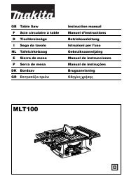
Operation (Fig. 6)<br />
Hold the tool firmly. Turn the tool on and then apply<br />
the wheel or disc to the workpiece.<br />
In general, keep the edge of the wheel or disc at an<br />
angle of about 15° – 30° to the workpiece surface.<br />
During the break-in period with a new wheel, do not<br />
work the tool in the B direction or it will cut into the<br />
workpiece. Once the edge of the wheel has been<br />
rounded off by use, the wheel may be worked in both<br />
A and B directions.<br />
WARNING:<br />
• It should never be necessary to force the tool. The<br />
weight of the tool applies adequate pressure. Forcing<br />
and excessive pressure could cause dangerous<br />
wheel breakage.<br />
• Continued use of a worn-out wheel may result in<br />
wheel explosion and serious personal injury.<br />
Depressed center wheel should not be used after it<br />
has been worn down to 115 <strong>mm</strong> in diameter. Use of<br />
the wheel after this point is unsafe and it should be<br />
removed from service and rendered unusable by<br />
intentional destruction.<br />
MAINTENANCE<br />
CAUTION:<br />
Always be sure that the tool is switched off and<br />
unplugged before carrying out any work on the tool.<br />
Replacement of carbon brushes (Fig. 7)<br />
Whenever carbon brushes must be replaced, they cut<br />
out the tool automatically. When this occurs, replace<br />
the carbon brushes at the same time. Use only<br />
identical carbon brushes.<br />
To maintain product safety and reliability, repairs,<br />
maintenance or adjustment should be carried out by a<br />
<strong>Makita</strong> Authorized Service Center.<br />
5