Acoplamento Flexomax GE
Acoplamento Flexomax GE
Acoplamento Flexomax GE

Create successful ePaper yourself
Turn your PDF publications into a flip-book with our unique Google optimized e-Paper software.
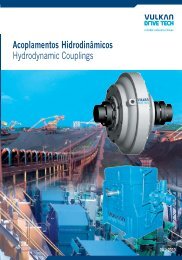
ACOPLAMENTO HIDRODINÂMICO<br />
CONTRA-RECUOS<br />
DENFLEX - NVD<br />
DISCFLEX<br />
EMBREA<strong>GE</strong>NS INDUSTRIAIS<br />
FLEXOMAX G<br />
FLEXOMAX GBN<br />
FLEXOMAX GSN<br />
PINOFLEX - NP<br />
SPEFLEX - N<br />
VULBRAFLEX VB<br />
VULKARDAN - E<br />
VUL-MEX<br />
2009/01
FLEXOMAX G<br />
<strong>GE</strong>NERALITIES<br />
The FLEXOMAX G is a flexible<br />
and torsionally elastic coupling.<br />
Its flexibility allows to join two<br />
shaft ends and accommodate<br />
axial, angular and radial<br />
misalignment that occur in every<br />
assembly. Due to the elastic<br />
characteristics this kind of<br />
coupling is able to absorb<br />
02<br />
shocks and vibrations of the<br />
machine, either from the driving<br />
or driven side. The elastic<br />
element is made of a special<br />
rubber, resistant to dust, water<br />
and oil.<br />
As the FLEXOMAX G has a<br />
smart design, it allows a quick<br />
mounting and does not need any<br />
We reserve the right of technical alterations without previous notice.<br />
lubrication, what minimizes the<br />
maintenance time. Due to its<br />
claws this coupling is considered<br />
as anti-rotative slipping.<br />
The FLEXOMAX G<br />
is available<br />
in 18 sizes, has several designs,<br />
a maximum torque capacity of<br />
97.200 Nm and admits shaft<br />
diameters up to 250 mm.
FLEXOMAX G<br />
<strong>GE</strong>NERALIDADES<br />
O FLEXOMAX G é um provenientes da máquina<br />
acoplamento flexível e acionada ou acionadora. Tem<br />
torcionalmente elástico. elemento elástico em borracha<br />
Sua flexibilidade permite resistente à poeira, água, óleo e<br />
desalinhamentos radiais, axiais intempéries.<br />
e angulares entre os eixos Por sua construção simplificada,<br />
acoplados e ainda, sendo o FLEXOMAX G permite<br />
torcionalmente elástico, instalação rápida e segura,<br />
absorve choques e vibrações dispensando lubrificação e<br />
Reservamo-nos o direito de alterações sem prévio aviso.<br />
minimizando a manutenção. Em<br />
função de suas garras, este<br />
acoplamento é à prova de<br />
deslizamento rotativo.<br />
O FLEXOMAX G é disponível<br />
em 18 tamanhos e várias formas<br />
construtivas, com capacidade de<br />
até 97.200 Nm e eixos de até 250<br />
mm de diâmetro.<br />
03
FLEXOMAX G<br />
SELECTION PROCEDURE<br />
To select the correct coupling it is<br />
necessary to take into account the torque<br />
of the driving machine and the<br />
irregularity degree of the system, as well<br />
as the magnitude of the masses to be<br />
Meq = CxNxFs<br />
n<br />
FOR SELECTING A COUPLING: Mnom Meq<br />
DRIVING MACHINE:<br />
We reserve the right of technical alterations without previous notice.<br />
04<br />
accelerated. To determine the<br />
appropriate size it is necessary to multiply<br />
the service factors below by the nominal<br />
torque of the driving machine, which will<br />
appoint the equivalent torque (Meq). The<br />
DRIVEN MACHINES<br />
a) Regular operation and small masses that have to be accelerated:<br />
- Centrifugal pumps for liquid goods, generators, fans N/n 0,05, gear reducer units, shafting<br />
nominal torque (Mnom) of the selected<br />
coupling shall be higher or equal to the<br />
equivalent torque.<br />
Meq = equivalent torque (Nm)<br />
N = power of the driving machine (kW/ HP)<br />
n = coupling working speed (rpm)<br />
Fs = F1 x F2 x F3 x F4 = service factor<br />
Mnom = coupling nominal torque (Nm)<br />
C = constant:<br />
9550 for power in kW<br />
7030 for power in HP<br />
Combustion engines with1-3cylinders<br />
Combustion engines with 4 or more cylinders<br />
Eletric motor and steam turbines<br />
b) Regular operation and smaller masses that have to be accelerated:<br />
- Plate bending machines, elevators, exhausters, belt conveyors for bulk materials, stirrers, liquid goods, light textile machines, turboblowers and compressors,<br />
fans N/n = 0,05 to 0,1, machine tools with rotating motion<br />
c) Irregular operation and medium masses that have to be accelerated:<br />
- Surface planing and thickening machines, rotaty piston blowers, rotary furnaces, printing and dying machines, belt conveyors for piece goods, hauling drums,<br />
generators, coilers, wood working machines, centrifugal pumps for semi-liquid goods, cooling drums, freight elevators, mixers, shredders, ring straightening<br />
machines, stirrers for semi-liquid goods, grinding machines, shaking screens, fans, N/n 0,1, winches<br />
d) Irregular operation and medium masses that have to be accelerated and additional impact loads:<br />
- Concrete mixers, threshing machines, drop hammers, mine fans, planing machines for metal, hollanders, endless chain transporters, kneading machines,<br />
reciprocating pumps and compressors with degree of irregularity 1:100 to 1:200, cranes, ball mills, milling courses, mills, passenger elevators, steel plate<br />
conveyors, press pumps, axial-flow pumps, pipe mills, tumbling barrels, light roller tables, shafts for ships, centrifugal mills, cable winches, drying drums and<br />
drying kilns, cylinder mills, washing machines, looms, centrifugal machines.<br />
e) Irregular operation and large masses that have to be accelerated and especially strong additional impact loads:<br />
- Excavators, lead rolling mills, wire pulls, rubber rolling machines, swing-hammer mills, hammers, pulp grinders, calendars, reciprocating pums with light<br />
flywheel, edge mills, presses, rotary-drilling gears, jolters, shears, forging presses, punch machines, sugarcane breakers.<br />
Service Factor - “F1”<br />
f) Irregular operation and very large masses that have to be accelerated and especially strong additional impact loads:<br />
- Horizontal saw frames, piston compressors and reciprocating pumps without flywheel, heavy roller tables, welding generators, stone breakers, multiple blade<br />
frame saws, rolling mills for metal, brick molding presses<br />
2,4 3,0 3,5<br />
g) Other equipments Upon inquiry<br />
DAILY SERVICE<br />
LIFE (hours)<br />
FACTOR - “F2”<br />
AMBIENT<br />
TEMPERATURE (ºC)<br />
* Upon inquiry<br />
FACTOR - “F3”<br />
over<br />
till<br />
over<br />
till<br />
-<br />
8<br />
1,0<br />
-<br />
75<br />
1,0<br />
8<br />
16<br />
1,07<br />
75<br />
85<br />
1,2<br />
16<br />
24<br />
1,10<br />
85<br />
-<br />
*<br />
STARTINGS<br />
PER HOUR<br />
MODE OF<br />
OPERATION<br />
ACC. TO A.M.<br />
TABLE FOR<br />
FACTORS F1<br />
a)<br />
b)<br />
c)<br />
d)<br />
e)<br />
f)<br />
g)<br />
01<br />
10<br />
11<br />
20<br />
1,5<br />
1,6<br />
Nos reservamos el derecho a las alteraciones sin previo aviso.<br />
21<br />
40<br />
FACTOR - “F4”<br />
1,8 2,1<br />
2,0 2,3<br />
1,7 2,2 2,5<br />
1,9 2,5 2,8<br />
41<br />
80<br />
2,1 2,8 3,1<br />
81<br />
160<br />
1 1,10 1,20 1,25 1,40 1,50<br />
1 1,10 1,15 1,20 1,35 1,40<br />
1 1,07 1,15 1,20 1,30 1,40<br />
1 1,07 1,12 1,15 1,20 1,30<br />
1 1,05 1,12 1,15 1,20 1,30<br />
1 1,05 1,10 1,12 1,12 1,12<br />
Upon inquiry<br />
over<br />
160
FLEXOMAX G<br />
SELEÇÃO DETALHADA<br />
Na seleção de um acoplamento é<br />
imprescindível considerar os momentos<br />
da máquina acionadora e o grau de<br />
irregularidade do sistema, como também<br />
a magnitude das massas a serem<br />
Meq =<br />
C x N x Fs<br />
n<br />
CONDIÇÃO PARA A<br />
SELEÇÃO DE UM ACOPLAMENTO: Mnom Meq<br />
* Sob consulta<br />
MÁQUINA ACIONADORA:<br />
We reserve the right of technical alterations without previous notice.<br />
aceleradas. Para determinação inicial do<br />
acoplamento é necessário considerar os<br />
fatores de serviço descritos abaixo, os<br />
quais multiplicados ao momento nominal<br />
da máquina acionadora, determinarão o<br />
MÁQUINAS ACIONADAS<br />
a) Com serviço regular e reduzidas massas a acelerar:<br />
- Bombas centrífugas para líquidos, geradores elétricos, ventiladores com N/n 0,05, etc.<br />
momento equivalente (Meq). O momento<br />
nominal (Mnom) do acoplamento<br />
escolhido deverá ser maior ou igual ao<br />
momento equivalente.<br />
Meq = momento equivalente (Nm)<br />
N = potência da máquina acionadora (kW/ cv)<br />
n = rotação de trabalho do acoplamento (rpm)<br />
Fs = F1 x F2 x F3 x F4 = fator de serviço<br />
Mnom = momento nominal do acoplamento (Nm)<br />
C = constante:<br />
Motor de combustão com 1 a 3 cilindros<br />
Motor de combustão com 4 ou mais cilindros<br />
Motor elétrico ou turbina a vapor<br />
b) Com serviço regular e pequenas massas a acelerar:<br />
- Pequenos elevadores, exaustores, correias transportadoras para materiais a granel, agitadores para líquidos, máquinas têxteis, compressores<br />
rotativos, escadas rolantes, ventiladores com N/n = 0,05 a 0,1, etc.<br />
c) Com serviço irregular e médias massas a acelerar:<br />
- Sopradores de êmbolo rotativo, fornos giratórios, máquinas impressoras, correias transportadoras para materiais brutos, guinchos de pontes<br />
rolantes, máquinas para madeira, bombas rotativas para semi-líquidos, elevadores de carga, agitadores para semi-líquidos, ventiladores com<br />
N/n 0,1, etc.<br />
d) Com serviço irregular e médias massas a acelerar, com choques leves:<br />
- Desfibradores de polpa, bombas e compressores de êmbolo com grau de desuniformidade de 1:100 à 1: 200, moinhos de bolas, bombas para<br />
substâncias pastosas, eixos de barcos, moinhos centrífugos, roscas transportadoras, picador de cana, desfibrador, moenda, mesa<br />
alimentadora, etc.<br />
e) Com serviço irregular e grandes massas a acelerar, com choques fortes:<br />
- Dragas, laminadores, trefiladores de arames, moinhos de martelo, calandras, bombas e compressores de êmbolo com volante pequeno,<br />
prensas, máquinas vibradoras, translação de carro e ponte rolante, etc.<br />
f) Com serviço irregular e massas muito grandes a acelerar, com choques muito fortes:<br />
- Compressores e bombas de êmbolo sem volante, geradores de solda, serras alternativas e trens de laminação de metais, etc.<br />
9550 para potência em kW<br />
7030 para potência em cv<br />
Fator de Serviço - “F1”<br />
g) Outros equipamentos Sob consulta<br />
FUNCIONAMENTO<br />
DIÁRIO (horas)<br />
FATOR - “F2”<br />
TEMPERATURA<br />
AMBIENTE (ºC)<br />
FATOR - “F3”<br />
mais de<br />
até<br />
mais de<br />
até<br />
-<br />
8<br />
1,0<br />
-<br />
75<br />
1,0<br />
8<br />
16<br />
1,07<br />
75<br />
85<br />
1,2<br />
16<br />
24<br />
1,10<br />
85<br />
-<br />
*<br />
PARTIDAS/HORA<br />
EM FUNÇÃO<br />
DO TIPO DE<br />
CARGA DA<br />
TABELA DE F1<br />
a)<br />
b)<br />
c)<br />
d)<br />
e)<br />
f)<br />
g)<br />
01<br />
10<br />
11<br />
20<br />
21<br />
40<br />
FATOR - “F4”<br />
1,5<br />
1,6<br />
Nos reservamos el derecho a las alteraciones sin previo aviso.<br />
05<br />
1,8 2,1<br />
2,0 2,3<br />
1,7 2,2 2,5<br />
1,9 2,5 2,8<br />
2,1 2,8 3,1<br />
2,4 3,0 3,5<br />
41<br />
80<br />
81<br />
160<br />
acima<br />
de<br />
160<br />
1 1,10 1,20 1,25 1,40 1,50<br />
1 1,10 1,15 1,20 1,35 1,40<br />
1 1,07 1,15 1,20 1,30 1,40<br />
1 1,07 1,12 1,15 1,20 1,30<br />
1 1,05 1,12 1,15 1,20 1,30<br />
1 1,05 1,10 1,12 1,12 1,12<br />
Sob consulta
FLEXOMAX G<br />
DESIGN / FORMAS CONSTRUCTIVAS<br />
DESIGN <strong>GE</strong><br />
DESIGN GG<br />
DESIGN GH<br />
DESIGN GLE<br />
DESIGN GLG<br />
DESIGN GLV<br />
We reserve the right of technical alterations without previous notice.<br />
06<br />
Pg. 09<br />
Pg. 10<br />
Pg. 11<br />
Pg. 12<br />
Pg. 13<br />
Pg. 14<br />
Basic design. It is necessary to displace axially one of the coupled machines to replace the elastic<br />
element.<br />
Acoplamiento básico. Para substituir el elemento elástico es necesario desplazar axialmente<br />
una de las máquinas acopladas.<br />
Coupling equipped with an axial sliding claw ring, what enables to turn either the driven or driving<br />
machine separately. Sliding claw ring allows inspection or replacement of the elastic element<br />
without displacing the coupled machines.<br />
Acoplamiento con capa de desplazamiento axial, lo que permite el accionamiento independiente<br />
de la máquina accionada o accionadora. El desplazamiento de la capa permite inspeccionar o<br />
substituir el elemento elástico sin desplazar las máquinas acopladas.<br />
Coupling equipped with radially removable spacer what enables to turn either the driven or<br />
driving machine separately and makes easier the maintenance of “back-pull-out” pumps.<br />
Removable spacer allows replacement of the elastic element without displacing the coupled<br />
machines.<br />
Acoplamiento con espaciador desplazable radialmente, esto permite el accionamiento<br />
independiente de la máquina accionadora o accionada. Mayor facilidad para mantención de<br />
bombas tipo “back-pull-out”. La remoción del distanciador permite el cambio del elemento<br />
elástico sin desplazar las máquinas acopladas<br />
Flange/shaft coupling. It is necessary to displace axially one of the coupled machines to replace<br />
the elastic element.<br />
Acoplamiento flanche/eje. Para substituir el elemento elástico es necesario desplazar<br />
axialmente una de las máquinas acopladas.<br />
Flange/shaft coupling equipped with an axial sliding claw ring what enables to turn either the<br />
driven or driving machine separately. Sliding claw ring allows replacement of the elastic element<br />
without displacing the coupled machines.<br />
Acoplamiento flanche/eje. Posee capa de desplazamiento axial, lo que permite el accionamiento<br />
independiente de la máquina accionadora o accionada. El desplazamiento de la capa permite<br />
substituir el elemento elástico sin desplazar las máquinas acopladas.<br />
Flange/shaft coupling equipped with inverted hub providing compact installations. It is necessary<br />
to displace axially one of the coupled machines to replace the elastic element.<br />
Acoplamiento flanche/eje, con cubo invertido posibilitando montajes compactas. Para substituir<br />
el elemento elástico es necesario desplazar axialmente una de las máquinas acopladas.<br />
Nos reservamos el derecho a las alteraciones sin previo aviso.
FLEXOMAX G<br />
FORMAS CONSTRUTIVAS<br />
FORMA E<br />
FORMA G<br />
FORMA H<br />
FORMA LE<br />
FORMA LG<br />
FORMA LV<br />
Pág. 07<br />
Pág. 08<br />
Pág. 09<br />
Pág. 10<br />
Pág. 11<br />
Pág. 12<br />
We reserve the right of technical alterations without previous notice.<br />
<strong>Acoplamento</strong> básico. Para substituir o elemento elástico é necessário deslocar<br />
axialmente uma das máquinas acopladas.<br />
<strong>Acoplamento</strong> com capa de deslocamento axial, o que permite o acionamento<br />
independente da máquina acionada ou acionadora. O afastamento da capa<br />
permite inspecionar ou substituir o elemento elástico sem deslocamento das<br />
máquinas acopladas.<br />
<strong>Acoplamento</strong> com espaçador removível radialmente, o que permite o<br />
acionamento independente da máquina acionada ou acionadora e maior<br />
facilidade para manutenção das bombas tipo “back-pull-out”. A remoção do<br />
espaçador permite substituir o elemento elástico sem deslocamento das<br />
máquinas acopladas.<br />
<strong>Acoplamento</strong> flange/eixo. Para substituir o elemento elástico é necessário<br />
deslocar uma das máquinas acopladas.<br />
<strong>Acoplamento</strong> flange/eixo com capa de deslocamento axial, o que permite o<br />
acionamento independente da máquina acionada ou acionadora. O<br />
afastamento da capa permite substituir o elemento elástico sem deslocamento<br />
das máquinas acopladas.<br />
<strong>Acoplamento</strong> flange/eixo, com cubo invertido possibilitando montagens<br />
compactas. Para substituir o elemento elástico é necessário deslocar<br />
axialmente uma das máquinas acopladas.<br />
Reservamo-nos o direito de alterações sem prévio aviso.<br />
07
FLEXOMAX G<br />
DESIGN/FORMA <strong>GE</strong><br />
Size<br />
Tam. l<br />
J<br />
(kgm )<br />
2<br />
Nom.<br />
Torque<br />
(Nm)<br />
Max.<br />
Torque<br />
(Nm)<br />
Rot.<br />
Max.<br />
(rpm)<br />
min max<br />
D D1 L<br />
S1<br />
50 20,5 41 12500 - 22 50 33 52,0 25 2,0 ± 0,5 0,0002<br />
67 38 72 10000 - 32 67 46 62,5 30 2,5 ± 0,5 0,0004<br />
82 81 162 8000 - 38 82 53 83,0 40 3,0 ± 1,0 0,0012<br />
97 170 340 7000 - 48 97 68 103,0 50 3,0 ± 1,0 0,0028<br />
112 270 540 6000 - 55 112 79 123,5 60 3,5 ± 1,0 0,0052<br />
128 432,5 865 5000 - 65 128 90 143,5 70 3,5 ± 1,0 0,0112<br />
148 675 1350 4500 - 80 148 107 163,5 80 3,5 ± 1,0 0,0190<br />
168 1125 2250 4000 - 90 168 124 183,5 90 3,5 ± 1,5 0,0460<br />
194 1800 3600 3500 - 105 194 140 203,5 100 3,5 ± 1,5 0,0894<br />
214 2700 5400 3000 - 115 214 157 224,0 110 4,0 ± 2,0 0,1506<br />
240 4320 8640 2750 - 125 240 179 244,0 120 4,0 ± 2,0 0,2506<br />
265 6750 13500 2500 44 130 265 198 285,5 140 5,5 ± 2,5 0,4306<br />
295 90000 18000 2250 50 140 295 214 308,0 150 8,0 ± 2,5 0,6856<br />
330 11700 23400 2000 56 170 330 248 328,0 160 8,0 ± 2,5 1,2606<br />
370 16380 32760 1750 63 195 370 278 368,0 180 8,0 ± 2,5 2,2200<br />
415 24300 48600 1500 69 215 415 315 408,0 200 8,0 ± 2,5 3,8600<br />
480 32400 64800 1400 103 230 480 350 448,0 220 8,0 ± 2,5 6,0500<br />
575 48600 97200 1200 116 250 575 380 488,0 240 8,0 ± 2,5 13,2000<br />
Where not indicated, consider units in mm. Onde não indicado, considerar unidades em mm.<br />
1) Note:<br />
a) Allowable interference for maximum bore:<br />
Size 50 - H7/j6<br />
Size 67 to 97 - H7/k6<br />
Size 112 to 214 - H7/m6<br />
Size 240 - H7/n6<br />
b) Allowable tolerance for keyway for maximum bore: JS9<br />
c) dmax considers keyways in accordance to DIN 6885/1. For keys in accordance to<br />
AGMAnorm, please consult us for dmax.<br />
Material:<br />
Item 10: Elastic element, rubber<br />
Item 11: Hub, gray cast iron<br />
Attention:<br />
The maximal speed on the table should be considered as maximal working limit. If the<br />
circumferential speed of the coupling is higher than 25 m/s, we recommend dynamic<br />
balancing according to VDI 2060, Q = 6,3.<br />
We reserve the right of technical alterations without previous notice.<br />
08<br />
ØD1<br />
d 1)<br />
Ød<br />
11 10<br />
11<br />
l l<br />
L<br />
S1<br />
ØD<br />
1) Nota:<br />
a) Interferência admissível para furo máximo:<br />
Tamanho 50 - H7/j6<br />
Tamanho 67 à 97 - H7/k6<br />
Tamanho 112 à 214 - H7/m6<br />
Tamanho 240 - H7/n6<br />
Reservamo-nos o direito de alterações sem prévio aviso.<br />
Weight<br />
Peso<br />
(kg)<br />
0,45<br />
0,93<br />
1,80<br />
3,50<br />
5,00<br />
7,90<br />
12,30<br />
18,40<br />
26,30<br />
35,70<br />
46,70<br />
66,30<br />
84,80<br />
121,00<br />
169,00<br />
237,00<br />
308,00<br />
430,00<br />
b) Tolerância admissível no rasgo de chaveta para furo máximo: JS9<br />
c) dmáx considerado para chaveta conforme Norma DIN 6885/1. Para chavetas<br />
conforme NormaAgma solicitamos consultar dmax.<br />
Material:<br />
Item 10: Elemento elástico em borracha<br />
Item 11: Cubo em ferro fundido cinzento<br />
Atenção:<br />
As rotações indicadas devem ser consideradas como limite de trabalho. Para<br />
velocidades periféricas maiores que 25 m/s, recomendamos no mínimo<br />
balanceamento dinâmico conforme VDI 2060, Q = 6,3
FLEXOMAX G<br />
DESIGN/FORMA GG<br />
Size<br />
Tam.<br />
82<br />
97<br />
112<br />
128<br />
148<br />
168<br />
194<br />
214<br />
240<br />
265<br />
295<br />
330<br />
370<br />
415<br />
480<br />
575<br />
Nom. Max. Rot.<br />
Torque Torque Max.<br />
(Nm) (Nm) (rpm)<br />
81<br />
170<br />
270<br />
432,5<br />
675<br />
1125<br />
1800<br />
2700<br />
4320<br />
6750<br />
9000<br />
11700<br />
16380<br />
24300<br />
32400<br />
48600<br />
162<br />
340<br />
540<br />
865<br />
1350<br />
2250<br />
3600<br />
5400<br />
8640<br />
13500<br />
18000<br />
23400<br />
32760<br />
48600<br />
64800<br />
97200<br />
8000<br />
7000<br />
6000<br />
5000<br />
4500<br />
4000<br />
3500<br />
3000<br />
2750<br />
2500<br />
2250<br />
2000<br />
1750<br />
1500<br />
1400<br />
1200<br />
Where not indicated, consider units in mm.<br />
1) Note:<br />
a) Allowable interference for maximum bore:<br />
Size 82 to 97 - H7/k6<br />
Size 112 to 214- H7/m6<br />
Size 240- H7/n6<br />
dd1<br />
d 1)<br />
min max<br />
- 38<br />
- 48<br />
- 55<br />
- 65<br />
- 80<br />
- 90<br />
- 105<br />
- 115<br />
- 125<br />
44 130<br />
50 140<br />
56 170<br />
63 195<br />
69 215<br />
103 230<br />
116 250<br />
d1 1)<br />
max<br />
28<br />
35<br />
42<br />
48<br />
60<br />
65<br />
75<br />
85<br />
95<br />
105<br />
115<br />
130<br />
150<br />
170<br />
200<br />
230<br />
b) Allowable tolerance for keyway for maximum bore: JS9<br />
c) dmax and d1max considers keyways in accordance to DIN 6885/1. For keys in<br />
accordance toAGMAnorm, please consult us for dmax and d1max. Material:<br />
Item 10: Elastic element, rubber<br />
Item 11: Hub, gray cast iron<br />
Item 12: Claw ring, gray cast iron<br />
Item 13: Hub, gray cast iron<br />
Attention:<br />
The maximal speed on the table should be considered as maximal working limit. If the<br />
circumferential speed of the coupling is higher than 25 m/s, we recommend dynamic<br />
balancing according to VDI 2060, Q = 6,3.<br />
ØD<br />
We reserve the right of technical alterations without previous notice.<br />
ØD1<br />
Ød<br />
11 10 12<br />
14<br />
l l<br />
D D1 D2 l S2l l<br />
82<br />
97<br />
112<br />
128<br />
148<br />
168<br />
194<br />
214<br />
240<br />
265<br />
295<br />
330<br />
370<br />
415<br />
480<br />
575<br />
S2<br />
53<br />
68<br />
79<br />
90<br />
107<br />
124<br />
140<br />
157<br />
179<br />
198<br />
214<br />
248<br />
278<br />
315<br />
350<br />
380<br />
44,5<br />
54,5<br />
64,5<br />
74,5<br />
92,5<br />
104,5<br />
121,5<br />
135,5<br />
146,0<br />
164,0<br />
181,0<br />
208,0<br />
241,0<br />
275,0<br />
324,0<br />
379,0<br />
Ød1<br />
ØD2<br />
12 ± 1,0<br />
13 ± 1,0<br />
13 ± 1,0<br />
14 ± 1,0<br />
16 ± 1,0<br />
18 ± 1,5<br />
21 ± 1,5<br />
23 ± 2,0<br />
27 ± 2,0<br />
30 ± 2,5<br />
34 ± 2,5<br />
36 ± 2,5<br />
39 ± 2,5<br />
41 ± 2,5<br />
45 ± 2,5<br />
45 ± 2,5<br />
40<br />
50<br />
60<br />
70<br />
80<br />
90<br />
100<br />
110<br />
120<br />
140<br />
150<br />
160<br />
180<br />
200<br />
220<br />
240<br />
Onde não indicado, considerar unidades em mm.<br />
1) Nota:<br />
a) Interferência admissível para furo máximo:<br />
Tamanho 82 a 97 - H7/k6<br />
Tamanho 112 a 214 - H7/m6<br />
Tamanho 240<br />
- H7/n6<br />
Reservamo-nos o direito de alterações sem prévio aviso.<br />
09<br />
J<br />
(kgm ) 2<br />
0,0014<br />
0,0032<br />
0,0059<br />
0,0123<br />
0,0232<br />
0,0488<br />
0,0961<br />
0,1601<br />
0,2629<br />
0,4573<br />
0,7360<br />
1,2962<br />
2,2883<br />
4,0000<br />
7,0000<br />
14,9000<br />
Weight<br />
Peso<br />
(kg)<br />
2<br />
4<br />
5<br />
8<br />
12<br />
18<br />
27<br />
36<br />
46<br />
65<br />
84<br />
117<br />
166<br />
234<br />
330<br />
472<br />
b) Tolerância admissível no rasgo de chaveta para furo máximo: JS9<br />
c) dmáx e d1máx considerado para chaveta conforme Norma DIN 6885/1. Para<br />
chavetas conforme NormaAgma solicitamos consultar dmáx e d1máx. Material:<br />
Item 10: Elemento elástico em borracha<br />
Item 11: Cubo em ferro fundido cinzento<br />
Item 12: Capa em ferro fundido cinzento<br />
Item 14: Cubo em ferro fundido cinzento<br />
Atenção:<br />
As rotações indicadas devem ser consideradas como limite de trabalho. Para<br />
velocidades periféricas maiores que 25 m/s, recomendamos no mínimo<br />
balanceamento dinâmico conforme VDI 2060, Q = 6,3
FLEXOMAX G<br />
DESIGN/FORMA GH<br />
Size<br />
Tam.<br />
Nom. Max. Rot.<br />
Torque Torque Max.<br />
(Nm) (Nm) (rpm)<br />
Where not indicated, consider units in mm.<br />
1) Note:<br />
a) Allowable interference for maximum bore:<br />
Size 67 to 97 - H7/k6<br />
Size 112 to 214 - H7/m6<br />
Size 240 - H7/n6<br />
b) Allowable tolerance for keyway for maximum bore: Js9<br />
c) dmax considers keyways in accordance to DIN 6885/1. For keys in accordance to<br />
AGMAnorm, please consult us for dmax.<br />
2) S 4= S 5= S 3/<br />
2. Other spacer dimensions can be obtained and supplied.<br />
Material:<br />
Item 10: Elastic element, rubber<br />
Item 15: Hub, gray cast iron<br />
Item 16: Spacer, gray cast iron<br />
Applications:<br />
“Back-pull-out” pumps, compressors, etc.<br />
Attention:<br />
The maximal speed on the table should be considered as maximal working limit. If the<br />
circumferential speed of the coupling is higher than 25 m/s, we recommend dynamic<br />
balancing according to VDI 2060, Q = 6,3.<br />
We reserve the right of technical alterations without previous notice.<br />
10<br />
mín<br />
d 1)<br />
máx<br />
ØD<br />
D D 1<br />
15 16 10 16<br />
15<br />
2)<br />
S4<br />
l l<br />
J (kgm )<br />
2<br />
S3<br />
L6<br />
(kg)<br />
J (kgm )<br />
l S S L S S L 1 3 6 3<br />
3<br />
6<br />
67 36 72 10000 - 32 67 45 30 2,5 ± 0,5 100 0,0012 160 2 140 0,0017 200 3 - - - - - - - -<br />
82 81 162 8000 - 38 82 53 40 3,0 ± 1,0 100 0,0027 180 3 140 0,0037 220 4 - - - - - - - -<br />
97 170 340 7000 - 48 97 68 50 3,0 ± 1,0 100 0,0059 200 6 140 0,0077 240 6 180 0,0120 280 10 - - - -<br />
112 270 540 6000 - 55 112 79 60 3,5 ± 1,0 100 0,0113 220 8 140 0,0138 260 9 180 0,0220 300 13 - - - -<br />
128 432,5 865 5000 - 65 128 90 70 3,5 ± 1,0 100 0,0207 240 12 140 0,0252 280 13 180 0,0380 320 18 - - - -<br />
148 675 1350 4500 - 80 148 107 80 3,5 ± 1,0 100 0,0396 260 18 140 0,0483 300 19 180 0,0570 340 21 - - - -<br />
168 1125 2250 4000 - 90 168 124 90 3,5 ± 1,5 100 0,0857 280 25 140 0,0898 320 27 180 0,0939 360 28 250 0,158 430 43<br />
194 1800 3600 3500 - 105 194 140 100 3,5 ± 1,5 100 0,1366 300 35 140 0,1568 340 37 180 0,1769 380 39 250 0,280 450 58<br />
214 2700 5400 3000 - 115 214 150 110 4,0 ± 2,0 100 0,2304 320 48 140 0,2525 360 50 180 0,2746 400 52 250 0,423 470 73<br />
240 4320 8640 2750 - 125 240 179 120 4,0 ± 2,0 100 0,3878 340 65 140 0,4258 380 68 180 0,4637 420 71 250 0,690 490 97<br />
265 6750 13500 2500 40 130 265 198 140 5,5 ± 2,5 100 0,6028 380 86 140 0,6561 420 89 180 0,7093 460 93 250 1,090 530 126<br />
295 9000 18000 2250 60 135 295 214 150 8,0 ± 2,5 - - - - 140 1,1050 440 117 180 1,2330 480 124 250 1,480 550 139<br />
330 11700 23400 2000 70 150 330 248 160 8,0 ± 2,5 - - - - 140 3,6200 460 152 180 3,6000 500 176 250 6,200 570 183<br />
S1<br />
2)<br />
S5<br />
Weight<br />
Peso<br />
2<br />
L 6<br />
Ød<br />
(kg)<br />
Weight<br />
Peso<br />
ØD1<br />
J (kgm )<br />
2<br />
Onde não indicado, considerar unidades em mm.<br />
(kg)<br />
1) Nota:<br />
a) Interferência admissível para furo máximo:<br />
Tamanho 67 a 97 - H7/k6<br />
Tamanho 112 a 214 - H7/m6<br />
Tamanho 240 - H7/n6<br />
b) Tolerância admissível no rasgo de chaveta para furo máximo: JS9<br />
c) dmáx considerado para chaveta conforme Norma DIN 6885/1. Para chavetas<br />
conforme NormaAgma solicitamos consultar dmáx.<br />
2) S4 =S5 =S3 / 2. Assim sendo, outras dimensões de espaçadores poderão ser<br />
obtidas e fornecidas.<br />
Material:<br />
Item 10: Elemento elástico em borracha<br />
Item 15: Cubo em ferro fundido cinzento<br />
Item 16: Espaçador em ferro fundido cinzento<br />
Aplicações:<br />
Bombas “back-pull-out”, compressores, etc.<br />
Atenção:<br />
As rotações indicadas devem ser consideradas como limite de trabalho. Para<br />
velocidades periféricas maiores que 25 m/s, recomendamos no mínimo<br />
balanceamento dinâmico conforme VDI 2060, Q = 6,3<br />
Weight<br />
Peso<br />
Nos reservamos el derecho a las alteraciones sin previo aviso.<br />
S 3<br />
J (kgm )<br />
2<br />
L 6<br />
(kg)<br />
Weight<br />
Peso
FLEXOMAX G<br />
DESIGN/FORMA GLE<br />
Size<br />
Tam. J<br />
(kgm )<br />
2<br />
d<br />
min max<br />
1)<br />
Nom. Max. Rot.<br />
Torque Torque Max.<br />
D D D D T d Z L l l l S 1 3 4 1 L 1 1 2 1<br />
(Nm) (Nm) (rpm)<br />
67<br />
82<br />
97<br />
112<br />
128<br />
148<br />
168<br />
194<br />
214<br />
240<br />
265<br />
295<br />
330<br />
370<br />
415<br />
480<br />
575<br />
36<br />
81<br />
170<br />
270<br />
432,5<br />
675<br />
1125<br />
1800<br />
2700<br />
4320<br />
6750<br />
9000<br />
11700<br />
16380<br />
24300<br />
32400<br />
48600<br />
72<br />
162<br />
340<br />
540<br />
865<br />
1350<br />
2250<br />
3600<br />
5400<br />
8640<br />
13500<br />
18000<br />
23400<br />
32760<br />
48600<br />
64800<br />
97200<br />
10000<br />
8000<br />
7000<br />
6000<br />
5000<br />
4500<br />
4000<br />
3500<br />
3000<br />
2750<br />
2500<br />
2250<br />
2000<br />
1750<br />
1500<br />
1400<br />
1200<br />
Where not indicated, consider units in mm.<br />
1) Note:<br />
a) Allowable interference for maximum bore:<br />
Size 67 to 97 - H7/k6<br />
Size 112 to 214 - H7/m6<br />
Size 240 - H7/n6<br />
-<br />
-<br />
-<br />
-<br />
-<br />
-<br />
-<br />
-<br />
-<br />
-<br />
44<br />
50<br />
56<br />
63<br />
69<br />
103<br />
116<br />
32<br />
38<br />
48<br />
55<br />
65<br />
80<br />
90<br />
105<br />
115<br />
125<br />
130<br />
140<br />
170<br />
195<br />
215<br />
230<br />
250<br />
67<br />
82<br />
97<br />
112<br />
128<br />
148<br />
168<br />
194<br />
214<br />
240<br />
265<br />
295<br />
330<br />
370<br />
415<br />
480<br />
575<br />
46<br />
53<br />
68<br />
79<br />
90<br />
107<br />
124<br />
140<br />
157<br />
179<br />
198<br />
214<br />
248<br />
278<br />
315<br />
350<br />
380<br />
We reserve the right of technical alterations without previous notice.<br />
30<br />
40<br />
50<br />
60<br />
70<br />
90<br />
100<br />
115<br />
130<br />
145<br />
160<br />
170<br />
200<br />
235<br />
270<br />
320<br />
400<br />
b) Allowable tolerance for keyway for maximum bore: JS9<br />
c) dmax considers keyways in accordance to DIN 6885/1. For keys in accordance to<br />
AGMAnorm, please consult us for dmax.<br />
Material:<br />
Item 10: E lastic element, rubber<br />
Item 11: Hub, gray cast iron<br />
Item 17: Flange, gray cast iron<br />
Attention:<br />
The maximal speed on the table should be considered as maximal working limit. If the<br />
circumferential speed of the coupling is higher than 25 m/s, we recommend dynamic<br />
balancing according to VDI 2060, Q = 6,3.<br />
ØZh8<br />
(nº of holes)<br />
(nº de agujeros)<br />
1<br />
ØD T<br />
4<br />
ØdL<br />
ØD3<br />
l2<br />
l1<br />
94<br />
108<br />
128<br />
142<br />
160<br />
180<br />
200<br />
224<br />
250<br />
282<br />
312<br />
348<br />
390<br />
440<br />
528<br />
568<br />
645<br />
17 10 11<br />
S1<br />
L1<br />
l<br />
6<br />
6<br />
6<br />
6<br />
6<br />
7<br />
8<br />
8<br />
8<br />
8<br />
8<br />
9<br />
9<br />
10<br />
10<br />
10<br />
10<br />
6,6<br />
6,6<br />
9<br />
9<br />
11<br />
11<br />
11<br />
14<br />
14<br />
18<br />
18<br />
18<br />
22<br />
22<br />
26<br />
26<br />
26<br />
Ød<br />
106<br />
120<br />
144<br />
158<br />
180<br />
200<br />
220<br />
248<br />
274<br />
314<br />
344<br />
380<br />
430<br />
480<br />
575<br />
615<br />
692<br />
ØD1<br />
ØD<br />
47,5<br />
59,0<br />
73,0<br />
85,5<br />
98,5<br />
111,5<br />
127,5<br />
141,5<br />
156,0<br />
169,0<br />
195,5<br />
210,0<br />
224,0<br />
250,0<br />
273,0<br />
293,0<br />
313,0<br />
30<br />
40<br />
50<br />
60<br />
70<br />
80<br />
90<br />
100<br />
110<br />
120<br />
140<br />
150<br />
160<br />
180<br />
200<br />
220<br />
240<br />
15<br />
16<br />
20<br />
22<br />
25<br />
28<br />
34<br />
38<br />
42<br />
45<br />
50<br />
52<br />
56<br />
62<br />
65<br />
65<br />
65<br />
8<br />
8<br />
10<br />
10<br />
13<br />
13<br />
13<br />
16<br />
16<br />
20<br />
20<br />
22<br />
25<br />
25<br />
30<br />
30<br />
30<br />
Onde não indicado, considerar unidades em mm.<br />
1) Nota:<br />
a) Interferência admissível para furo máximo:<br />
Tamanho 67 a 97 - H7/k6<br />
Tamanho 112 a 214 - H7/m6<br />
Tamanho 240 - H7/n6<br />
2,5 ± 0,5<br />
3,0 ± 1,0<br />
3,0 ± 1,0<br />
3,5 ± 1,0<br />
3,5 ± 1,0<br />
3,5 ± 1,0<br />
3,5 ± 1,5<br />
3,5 ± 1,5<br />
4,0 ± 2,0<br />
4,0 ± 2,0<br />
5,5 ± 2,5<br />
8,0 ± 2,5<br />
8,0 ± 2,5<br />
8,0 ± 2,5<br />
8,0 ± 2,5<br />
8,0 ± 2,5<br />
8,0 ± 2,5<br />
Reservamo-nos o direito de alterações sem prévio aviso.<br />
11<br />
0,0010<br />
0,0019<br />
0,0046<br />
0,0075<br />
0,0164<br />
0,0405<br />
0,0504<br />
0,0967<br />
0,1585<br />
0,2757<br />
0,4635<br />
0,7382<br />
1,3620<br />
2,2570<br />
4,5200<br />
7,0000<br />
13,2250<br />
Weight<br />
Peso<br />
(kg)<br />
1<br />
2<br />
3<br />
4<br />
6<br />
9<br />
13<br />
19<br />
26<br />
34<br />
48<br />
61<br />
89<br />
121<br />
174<br />
219<br />
295<br />
b) Tolerância admissível no rasgo de chaveta para furo máximo: JS9<br />
c) dmáx considerado para chaveta conforme Norma DIN 6885/1. Para chavetas<br />
conforme NormaAgma solicitamos consultar dmáx.<br />
Material:<br />
Item 10: Elemento elástico em borracha<br />
Item 11: Cubo em ferro fundido cinzento<br />
Item 17: Flange em ferro fundido cinzento<br />
Atenção:<br />
As rotações indicadas devem ser consideradas como limite de trabalho. Para<br />
velocidades periféricas maiores que 25 m/s, recomendamos no mínimo<br />
balanceamento dinâmico conforme VDI 2060, Q = 6,3
FLEXOMAX G<br />
DESIGN/FORMA GLG<br />
Size<br />
Tam.<br />
82<br />
97<br />
112<br />
128<br />
148<br />
168<br />
194<br />
214<br />
240<br />
265<br />
295<br />
330<br />
370<br />
415<br />
480<br />
575<br />
Nom. Max. Rot.<br />
Torque Torque Max.<br />
(Nm) (Nm) (rpm)<br />
81<br />
170<br />
270<br />
432,5<br />
675<br />
1125<br />
1800<br />
2700<br />
4320<br />
6750<br />
9000<br />
11700<br />
16380<br />
24300<br />
32400<br />
48600<br />
162<br />
340<br />
540<br />
865<br />
1350<br />
2250<br />
3600<br />
5400<br />
8640<br />
13500<br />
18000<br />
23400<br />
32760<br />
48600<br />
64800<br />
97200<br />
1) Note:<br />
a) Allowable interference for maximum bore:<br />
Size 82 to 97 - H7/k6<br />
Size 112 to 214 - H7/m6<br />
Size 240 - H7/n6<br />
We reserve the right of technical alterations without previous notice.<br />
12<br />
8000<br />
7000<br />
6000<br />
5000<br />
4500<br />
4000<br />
3500<br />
3000<br />
2750<br />
2500<br />
2250<br />
2000<br />
1750<br />
1500<br />
1400<br />
1200<br />
Where not indicated, consider units in mm.<br />
d1 1)<br />
min max<br />
-<br />
-<br />
-<br />
-<br />
-<br />
-<br />
-<br />
-<br />
-<br />
44<br />
50<br />
56<br />
63<br />
69<br />
103<br />
116<br />
28<br />
35<br />
42<br />
48<br />
60<br />
65<br />
75<br />
85<br />
95<br />
105<br />
115<br />
130<br />
150<br />
170<br />
200<br />
230<br />
ØZh8<br />
(nº of holes)<br />
D<br />
4 1 (nº de agujeros)<br />
ØD T<br />
82<br />
97<br />
112<br />
128<br />
148<br />
168<br />
194<br />
214<br />
240<br />
265<br />
295<br />
330<br />
370<br />
415<br />
480<br />
575<br />
ØdL<br />
ØD3<br />
l2<br />
D2 D3 D4 T1 dL Z L2 l l1 l2 S2<br />
44,5<br />
54,5<br />
64,5<br />
74,5<br />
92,5<br />
104,5<br />
121,5<br />
135,5<br />
146,0<br />
164,0<br />
181,0<br />
208,0<br />
241,0<br />
275,0<br />
324,0<br />
379,0<br />
l1<br />
40<br />
50<br />
60<br />
70<br />
90<br />
100<br />
115<br />
130<br />
145<br />
160<br />
170<br />
200<br />
235<br />
270<br />
320<br />
400<br />
b) Allowable tolerance for keyway for maximum bore: JS9<br />
c) d1max considers keyways in accordance to DIN 6885/1. For keys in accordance to<br />
AGMAnorm, please consult us for d1max. Material:<br />
Item 10: Elastic element, rubber<br />
Item 12: Claw ring, gray cast iron<br />
Item 14: Hub, gray cast iron<br />
Item 17: Flange, gray cast iron<br />
Attention:<br />
The maximal speed on the table should be considered as maximal working limit. If the<br />
circumferential speed of the coupling is higher than 25 m/s, we recommend dynamic<br />
balancing according to VDI 2060, Q = 6,3.<br />
S2<br />
108<br />
128<br />
142<br />
160<br />
180<br />
200<br />
224<br />
250<br />
282<br />
312<br />
348<br />
390<br />
440<br />
528<br />
568<br />
645<br />
17 10 12 14<br />
L2<br />
6<br />
6<br />
6<br />
6<br />
7<br />
8<br />
8<br />
8<br />
8<br />
8<br />
9<br />
9<br />
10<br />
10<br />
10<br />
10<br />
l<br />
6,6<br />
9<br />
9<br />
11<br />
11<br />
11<br />
14<br />
14<br />
18<br />
18<br />
18<br />
22<br />
22<br />
26<br />
26<br />
26<br />
Ød1<br />
120<br />
144<br />
158<br />
180<br />
200<br />
220<br />
248<br />
274<br />
314<br />
344<br />
380<br />
430<br />
480<br />
575<br />
615<br />
692<br />
ØD2<br />
ØD<br />
68<br />
83<br />
95<br />
109<br />
124<br />
142<br />
159<br />
175<br />
192<br />
220<br />
236<br />
252<br />
281<br />
306<br />
330<br />
350<br />
40<br />
50<br />
60<br />
70<br />
80<br />
90<br />
100<br />
110<br />
120<br />
140<br />
150<br />
160<br />
180<br />
200<br />
220<br />
240<br />
16<br />
20<br />
22<br />
25<br />
28<br />
34<br />
38<br />
42<br />
45<br />
50<br />
52<br />
56<br />
62<br />
65<br />
65<br />
65<br />
8<br />
10<br />
10<br />
13<br />
13<br />
13<br />
16<br />
16<br />
20<br />
20<br />
22<br />
25<br />
25<br />
30<br />
30<br />
30<br />
Onde não indicado, considerar unidades em mm.<br />
1) Nota:<br />
a) Interferência admissível para furo máximo:<br />
Tamanho 82 a 97 - H7/k6<br />
Tamanho 112 a 214 - H7/m6<br />
Tamanho 240 - H7/n6<br />
12 ± 1,0<br />
13 ± 1,0<br />
13 ± 1,0<br />
14 ± 1,0<br />
16 ± 1,0<br />
18 ± 1,5<br />
21 ± 1,5<br />
23 ± 2,0<br />
27 ± 2,0<br />
30 ± 2,5<br />
34 ± 2,5<br />
36 ± 2,5<br />
39 ± 2,5<br />
41 ± 2,5<br />
45 ± 2,5<br />
45 ± 2,5<br />
J<br />
(kgm ) 2<br />
0,0021<br />
0,0049<br />
0,0082<br />
0,0174<br />
0,0292<br />
0,0533<br />
0,1034<br />
0,1684<br />
0,2902<br />
0,4907<br />
0,7962<br />
1,4052<br />
2,3755<br />
4,6600<br />
7,2000<br />
12,4250<br />
Reservamo-nos o direito de alterações sem prévio aviso.<br />
Weight<br />
Peso<br />
(kg)<br />
2<br />
3<br />
4<br />
6<br />
9<br />
13<br />
19<br />
26<br />
34<br />
47<br />
61<br />
86<br />
121<br />
171<br />
240<br />
338<br />
b) Tolerância admissível no rasgo de chaveta para furo máximo: JS9<br />
c) d1máx considerado para chaveta conforme Norma DIN 6885/1. Para chavetas<br />
conforme NormaAgma solicitamos consultar d1máx. Material:<br />
Item 10: Elemento elástico em borracha<br />
Item 12: Capa em ferro fundido cinzento<br />
Item 14: Cubo em ferro fundido cinzento<br />
Item 17: Flange em ferro fundido cinzento<br />
Atenção:<br />
As rotações indicadas devem ser consideradas como limite de trabalho. Para<br />
velocidades periféricas maiores que 25 m/s, recomendamos no mínimo<br />
balanceamento dinâmico conforme VDI 2060, Q = 6,3
FLEXOMAX G<br />
DESIGN/FORMA GLV<br />
Size<br />
Tam.<br />
97<br />
112<br />
128<br />
148<br />
168<br />
194<br />
214<br />
240<br />
265<br />
295<br />
Nom. Max. Rot.<br />
Torque Torque Max.<br />
(Nm) (Nm) (rpm)<br />
170<br />
270<br />
432,5<br />
675<br />
1125<br />
1800<br />
2700<br />
4320<br />
6750<br />
9000<br />
340<br />
540<br />
865<br />
1350<br />
2250<br />
3600<br />
5400<br />
8640<br />
13500<br />
18000<br />
7000<br />
6000<br />
5000<br />
4500<br />
4000<br />
3500<br />
3000<br />
2750<br />
2500<br />
2250<br />
Where not indicated, consider units in mm.<br />
d4 1)<br />
min max<br />
- 30<br />
- 35<br />
- 42<br />
- 55<br />
- 60<br />
- 70<br />
- 80<br />
42 90<br />
54 100<br />
54 110<br />
D D3 D4 D6<br />
97<br />
112<br />
128<br />
148<br />
168<br />
194<br />
214<br />
240<br />
265<br />
295<br />
50<br />
60<br />
70<br />
90<br />
100<br />
115<br />
130<br />
145<br />
160<br />
170<br />
128<br />
142<br />
160<br />
180<br />
200<br />
224<br />
250<br />
282<br />
312<br />
348<br />
1) Note:<br />
a) Allowable interference for maximum bore:<br />
Size 97 - H7/k6<br />
Size 112 to 214 - H7/m6<br />
Size 240 - H7/n6<br />
b) Allowable tolerance for keyway for maximum bore: JS9<br />
c) d4max considers keyways in accordance to DIN 6885/1. For keys in accordance to<br />
AGMAnorm, please consult us for d4max. Material:<br />
Item 10: Elastic element, rubber<br />
Item 17: Flange, gray cast iron<br />
Item 22: Hub, gray cast iron<br />
Attention:<br />
The maximal speed on the table should be considered as maximal working limit. If the<br />
circumferential speed of the coupling is higher than 25 m/s, we recommend dynamic<br />
balancing according to VDI 2060, Q = 6,3.<br />
We reserve the right of technical alterations without previous notice.<br />
ØZh8<br />
(nº of holes)<br />
4 1 (nº de agujeros)<br />
ØD T<br />
ØD3<br />
ØdL<br />
ØD6<br />
45<br />
55<br />
65<br />
85<br />
95<br />
107<br />
122<br />
137<br />
152<br />
160<br />
l2<br />
T1 dL Z L4 L5 l1 l2 l3 S1<br />
6<br />
6<br />
6<br />
7<br />
8<br />
8<br />
8<br />
8<br />
8<br />
9<br />
l1<br />
L5<br />
9<br />
9<br />
11<br />
11<br />
11<br />
14<br />
14<br />
18<br />
18<br />
18<br />
L4<br />
17 10 22<br />
S1<br />
l3<br />
144<br />
158<br />
180<br />
200<br />
220<br />
248<br />
274<br />
314<br />
344<br />
380<br />
Ød4<br />
ØD<br />
38<br />
43<br />
48<br />
53<br />
65<br />
75<br />
82<br />
92<br />
105<br />
105<br />
38<br />
43<br />
48<br />
60<br />
70<br />
80<br />
90<br />
100<br />
110<br />
120<br />
20<br />
22<br />
25<br />
28<br />
34<br />
38<br />
42<br />
45<br />
50<br />
52<br />
10<br />
10<br />
13<br />
13<br />
13<br />
16<br />
16<br />
20<br />
20<br />
22<br />
15,0<br />
17,5<br />
19,5<br />
21,5<br />
27,5<br />
33,5<br />
36,0<br />
43,0<br />
49,5<br />
45,0<br />
Onde não indicado, considerar unidades em mm.<br />
1) Nota:<br />
a) Interferência admissível para furo máximo:<br />
Tamanho 97 - H7/k6<br />
Tamanho 112 a 214 - H7/m6<br />
Tamanho 240 - H7/n6<br />
3,0 ± 1,0<br />
3,5 ± 1,0<br />
3,5 ± 1,0<br />
3,5 ± 1,0<br />
3,5 ± 1,0<br />
3,5 ± 1,0<br />
4,0 ± 2,0<br />
4,0 ± 2,0<br />
5,5 ± 2,5<br />
8,0 ± 2,5<br />
Reservamo-nos o direito de alterações sem prévio aviso.<br />
13<br />
J<br />
(kgm ) 2<br />
0,0040<br />
0,0065<br />
0,0138<br />
0,0208<br />
0,0417<br />
0,0790<br />
0,1302<br />
0,2313<br />
0,4732<br />
0,6132<br />
Weight<br />
Peso<br />
(kg)<br />
2,3<br />
2,9<br />
4,6<br />
6,8<br />
9,7<br />
14,3<br />
20,2<br />
28,0<br />
38,4<br />
46,0<br />
b) Tolerância admissível no rasgo de chaveta para furo máximo: JS9<br />
c) d4máx considerado para chaveta conforme Norma DIN 6885/1. Para chavetas<br />
conforme NormaAgma solicitamos consultar d4máx. Material:<br />
Item 10: Elemento elástico em borracha<br />
Item 17: Flange em ferro fundido cinzento<br />
Item 22: Cubo em ferro fundido cinzento<br />
Atenção:<br />
As rotações indicadas devem ser consideradas como limite de trabalho. Para<br />
velocidades periféricas maiores que 25 m/s, recomendamos no mínimo<br />
balanceamento dinâmico conforme VDI 2060, Q = 6,3
FLEXOMAX G<br />
DESIGN/FORMA <strong>GE</strong>B<br />
Size<br />
Tam.<br />
112<br />
128<br />
148<br />
168<br />
194<br />
214<br />
240<br />
265<br />
295<br />
330<br />
370<br />
415<br />
Nom. Max. Rot.<br />
Torque Torque Max.<br />
(Nm) (Nm) (rpm)<br />
270<br />
432,5<br />
675<br />
540<br />
865<br />
1350<br />
1125 2250<br />
1800 3600<br />
2700 5400<br />
4320 8640<br />
6750 13500<br />
9000 18000<br />
11700 23400<br />
16380<br />
24300<br />
32760<br />
48600<br />
We reserve the right of technical alterations without previous notice.<br />
14<br />
6000<br />
5000<br />
4500<br />
4000<br />
3500<br />
3000<br />
2750<br />
2500<br />
2250<br />
2000<br />
1750<br />
1500<br />
Where not indicated, consider units in mm.<br />
dd2<br />
min max max<br />
1) Note:<br />
a) Allowable interference for maximum bore:<br />
Size 112 to 214 - H7/m6<br />
Size 240 - H7/n6<br />
b) Allowable tolerance for keyway for maximum bore: JS9<br />
c) dmax and d2max considers keyways in accordance to DIN 6885/1. For keys in<br />
accordance toAGMAnorm, please consult us for dmax and d2máx. Material:<br />
Item 10: Elastic element, rubber<br />
Item 11: Hub, gray cast iron<br />
Item 18: Hub, gray cast iron<br />
Item 19: Brake drum, nodular cast iron<br />
Attention:<br />
The maximal speed on the table should be considered as maximal working limit. If the<br />
circumferential speed of the coupling is higher than 25 m/s, we recommend dynamic<br />
balancing according to VDI 2060, Q = 6,3.<br />
-<br />
-<br />
-<br />
-<br />
-<br />
-<br />
-<br />
-<br />
44<br />
56<br />
63<br />
69<br />
d 1)<br />
55<br />
65<br />
80<br />
90<br />
105<br />
115<br />
125<br />
130<br />
140<br />
170<br />
195<br />
215<br />
ØDB<br />
Ød2<br />
d2 1)<br />
42<br />
52<br />
58<br />
72<br />
85<br />
92<br />
102<br />
120<br />
130<br />
150<br />
170<br />
185<br />
18 19 10 11<br />
C B<br />
l<br />
D DB B C L l S1<br />
112<br />
128<br />
148<br />
168<br />
194<br />
214<br />
240<br />
265<br />
295<br />
330<br />
370<br />
415<br />
L<br />
200<br />
200<br />
250<br />
250<br />
315<br />
315<br />
315<br />
400<br />
400<br />
500<br />
500<br />
500<br />
630<br />
630<br />
710<br />
710<br />
710<br />
S1<br />
l<br />
75<br />
75<br />
95<br />
95<br />
118<br />
118<br />
118<br />
150<br />
150<br />
190<br />
190<br />
190<br />
236<br />
236<br />
265<br />
265<br />
265<br />
Ød<br />
ØD<br />
10<br />
15<br />
15<br />
20<br />
10<br />
20<br />
20<br />
15<br />
15<br />
10<br />
20<br />
30<br />
5<br />
10<br />
0<br />
5<br />
20<br />
123,5<br />
143,5<br />
163,5<br />
183,5<br />
203,5<br />
224,0<br />
244,0<br />
285,5<br />
308,0<br />
328,0<br />
368,0<br />
408,0<br />
60<br />
70<br />
80<br />
90<br />
100<br />
110<br />
120<br />
140<br />
150<br />
160<br />
180<br />
200<br />
Onde não indicado, considerar unidades em mm.<br />
1) Nota:<br />
a) Interferência admissível para furo máximo:<br />
Tamanho 112 a 214 - H7/m6<br />
Tamanho 240 - H7/n6<br />
3,5 ± 1,0<br />
3,5 ± 1,0<br />
3,5 ± 1,0<br />
3,5 ± 1,5<br />
3,5 ± 1,5<br />
4,0 ± 2,0<br />
4,0 ± 2,0<br />
5,5 ± 2,5<br />
8,0 ± 2,5<br />
8,0 ± 2,5<br />
8,0 ± 2,5<br />
8,0 ± 2,5<br />
J<br />
(kgm ) 2<br />
0,0378<br />
0,0437<br />
0,1157<br />
0,1407<br />
0,3507<br />
0,3899<br />
0,4515<br />
1,0555<br />
1,1453<br />
2,7958<br />
2,9880<br />
3,2106<br />
8,5806<br />
9,1480<br />
15,2583<br />
16,2170<br />
17,7661<br />
Reservamo-nos o direito de alterações sem prévio aviso.<br />
Weight<br />
Peso<br />
(kg)<br />
9<br />
12<br />
20<br />
27<br />
33<br />
41<br />
50<br />
64<br />
73<br />
97<br />
117<br />
135<br />
194<br />
229<br />
257<br />
304<br />
367<br />
b) Tolerância adminssível no rasgo de chaveta para furo máximo: JS9<br />
c) dmáx e d2máx considerado para chaveta conforme Norma DIN 6885/1. Para<br />
chavetas conforme NormaAgma solicitamos consultar dmáx e d2máx. Material:<br />
Item 10: Elemento elástico em borracha<br />
Item 11: Cubo em ferro fundido cinzento<br />
Item 18: Cubo em ferro fundido cinzento<br />
Item 19: Polia de freio em ferro fundido nodular<br />
Atenção:<br />
As rotações indicadas devem ser consideradas como limite de trabalho. Para<br />
velocidades periféricas maiores que 25 m/s, recomendamos no mínimo<br />
balanceamento dinâmico conforme VDI 2060, Q = 6,3
FLEXOMAX G<br />
DESIGN/FORMA GGB<br />
Size<br />
Tam.<br />
112<br />
128<br />
148<br />
168<br />
194<br />
214<br />
240<br />
265<br />
295<br />
330<br />
370<br />
415<br />
Nom. Max. Rot.<br />
Torque Torque Max.<br />
(Nm) (Nm) (rpm)<br />
270<br />
432,5<br />
675<br />
1125<br />
1800<br />
2700<br />
4320<br />
6750<br />
9000<br />
11700<br />
16380<br />
24300<br />
540<br />
865<br />
1350<br />
2250<br />
3600<br />
5400<br />
8640<br />
13500<br />
18000<br />
23400<br />
32760<br />
48600<br />
6000<br />
5000<br />
4500<br />
4000<br />
3500<br />
3000<br />
2750<br />
2500<br />
2250<br />
2000<br />
1750<br />
1500<br />
Where not indicated, consider units in mm.<br />
d d<br />
1 2<br />
d1 1)<br />
d2 1)<br />
min max max<br />
1) Note:<br />
a) Allowable interference for maximum bore:<br />
Size 112 to 214 - H7/m6<br />
Size 240 - H7/n6<br />
b) Allowable tolerance for keyway for maximum bore: JS9<br />
c) d1max and d2max considers keyways in accordance to DIN 6885/1. For keys in<br />
accordance toAGMAnorm, please consult us for d1max and d2max. Material:<br />
Item 10: Elastic element, rubber<br />
Item 12: Claw ring, gray cast iron<br />
Item 14: Hub, gray cast iron<br />
Item 18: Hub, gray cast iron<br />
Item 19: Brake drum, nodular cast iron<br />
Attention:<br />
The maximal speed on the table should be considered as maximal working limit. If the<br />
circumferential speed of the coupling is higher than 25 m/s, we recommend dynamic<br />
balancing according to VDI 2060, Q = 6,3.<br />
42<br />
52<br />
58<br />
102<br />
120<br />
130<br />
150<br />
170<br />
185<br />
We reserve the right of technical alterations without previous notice.<br />
-<br />
-<br />
-<br />
-<br />
20<br />
28<br />
38<br />
44<br />
50<br />
56<br />
63<br />
69<br />
ØDB<br />
42<br />
48<br />
60<br />
65<br />
75<br />
85<br />
95<br />
105<br />
115<br />
130<br />
150<br />
170<br />
Ød2<br />
72<br />
85<br />
92<br />
18 19 10 12 14<br />
C B<br />
D DB B C L3l S2<br />
112<br />
128<br />
148<br />
168<br />
194<br />
214<br />
240<br />
265<br />
295<br />
330<br />
370<br />
415<br />
l S2 l<br />
L3<br />
200<br />
200<br />
250<br />
250<br />
315<br />
315<br />
315<br />
400<br />
400<br />
500<br />
500<br />
500<br />
630<br />
630<br />
710<br />
710<br />
710<br />
75<br />
75<br />
95<br />
95<br />
118<br />
118<br />
118<br />
150<br />
150<br />
190<br />
190<br />
190<br />
236<br />
236<br />
265<br />
265<br />
265<br />
Ød1<br />
10<br />
15<br />
15<br />
20<br />
10<br />
20<br />
20<br />
15<br />
15<br />
10<br />
20<br />
30<br />
5<br />
10<br />
0<br />
5<br />
20<br />
ØD<br />
133<br />
154<br />
176<br />
198<br />
221<br />
243<br />
267<br />
310<br />
334<br />
356<br />
399<br />
441<br />
60<br />
70<br />
80<br />
90<br />
100<br />
110<br />
120<br />
140<br />
150<br />
160<br />
180<br />
200<br />
Onde não indicado, considerar unidades em mm.<br />
1) Nota:<br />
a) Interferência admissível para furo máximo:<br />
Tamanho 112 a 214 - H7/m6<br />
Tamanho 240 - H7/n6<br />
13 ± 1,0<br />
14 ± 1,0<br />
16 ± 1,0<br />
18 ± 1,5<br />
21 ± 1,5<br />
23 ± 2,0<br />
27 ± 2,0<br />
30 ± 2,5<br />
34 ± 2,5<br />
36 ± 2,5<br />
39 ± 2,5<br />
41 ± 2,5<br />
Reservamo-nos o direito de alterações sem prévio aviso.<br />
15<br />
J<br />
(kgm )<br />
2<br />
0,0384<br />
0,0447<br />
0,1198<br />
0,1435<br />
0,3535<br />
0,3965<br />
0,4505<br />
1,0555<br />
1,1453<br />
2,7325<br />
3,0150<br />
3,2600<br />
8,6300<br />
9,1825<br />
15,2950<br />
16,2850<br />
17,9050<br />
Weight<br />
Peso<br />
(kg)<br />
9<br />
13<br />
20<br />
27<br />
33<br />
41<br />
49<br />
64<br />
72<br />
96<br />
116<br />
135<br />
194<br />
226<br />
254<br />
302<br />
365<br />
b) Tolerância admissível no rasgo de chaveta para furo máximo: JS9<br />
c) d1máx e d2máx considerado para chaveta conforme Norma DIN 6885/1. Para<br />
chavetas conforme NormaAgma solicitamos consultar d1máx e d2máx. Material:<br />
Item 10: Elemento elástico em borracha<br />
Item 12: Capa em ferro fundido cinzento<br />
Item 14: Cubo em ferro fundido cinzento<br />
Item 18: Cubo em ferro fundido cinzento<br />
Item 19: Polia de freio em ferro nodular<br />
Atenção:<br />
As rotações indicadas devem ser consideradas como limite de trabalho. Para<br />
velocidades periféricas maiores que 25 m/s, recomendamos no mínimo<br />
balanceamento dinâmico conforme VDI 2060, Q = 6,3
FLEXOMAX G<br />
DESIGN/FORMA <strong>GE</strong>TW<br />
ØA<br />
ØF<br />
Execution 1<br />
Execução 1<br />
(nº of holes)<br />
8 3 (nº de furos)<br />
ØD T<br />
H7<br />
j6<br />
ØD7<br />
Execution 2<br />
Execução 2<br />
ØD6<br />
Ød2<br />
Where not indicated, consider units in mm.<br />
1) Note:<br />
a) Allowable interference for maximum bore:<br />
Size 112 to 214 - H7/m6<br />
Size 240 - H7/n6<br />
b) Allowable tolerance for keyway for maximum bore: JS9<br />
c) dmax, d1max and d2max considers keyways in accordance to DIN 6885/1. For<br />
keys in accordance to AGMA norm, please consult us for dmax, d1max and<br />
d2max.<br />
Material:<br />
Item 10: Elastic element, rubber<br />
Item 11: Hub, gray cast iron<br />
Item 12: Claw ring, gray cast iron<br />
Item 14: Hub, gay cast iron<br />
Item 18: Hub, gray cast iron<br />
Item 23: Brake disc, nodular cast iron<br />
Attention:<br />
The maximal speed on the table should be considered as maximal working limit. If the<br />
circumferential speed of the coupling is higher than 25 m/s, we recommend dynamic<br />
balancing according to VDI 2060, Q = 6,3.<br />
We reserve the right of technical alterations without previous notice.<br />
16<br />
18 23<br />
C2<br />
C1<br />
12,7<br />
L<br />
12,7<br />
S1<br />
10<br />
l l<br />
11<br />
Ød<br />
ØD1<br />
ØD<br />
C2<br />
DESIGN/FORMA GGTW<br />
12,7<br />
12,7<br />
Onde não indicado, considerar unidades em mm.<br />
C1<br />
18 23 10 12 14<br />
1) Nota:<br />
a) Interferência admissível para furo máximo:<br />
Tamanho 112 a 214 - H7/m6<br />
Tamanho 240 - H7/n6<br />
l<br />
L3<br />
Reservamo-nos o direito de alterações sem prévio aviso.<br />
S2<br />
l<br />
Ød1<br />
Execution 1<br />
Execução 1<br />
ØD2<br />
ØD<br />
Execution 2<br />
Execução 2<br />
d<br />
max<br />
1)<br />
d1<br />
max<br />
55<br />
65<br />
80<br />
90<br />
105<br />
115<br />
125<br />
130<br />
140<br />
170<br />
195<br />
215<br />
1)<br />
d2<br />
max<br />
42<br />
48<br />
60<br />
65<br />
75<br />
85<br />
95<br />
105<br />
115<br />
130<br />
150<br />
170<br />
1)<br />
d, d<br />
Size<br />
d<br />
Tam.<br />
A F C1 C2 D D1 D2 D6 D7 D8 l L L3 T3 S1 S2<br />
112<br />
6000<br />
42<br />
128<br />
5000<br />
52<br />
148<br />
4500<br />
58<br />
168<br />
4000<br />
72<br />
194<br />
3500<br />
85<br />
214<br />
3000<br />
92<br />
240<br />
2750<br />
102<br />
265<br />
2500<br />
120<br />
295<br />
2250<br />
130<br />
330<br />
2000<br />
150<br />
370<br />
1750<br />
170<br />
415<br />
1500<br />
185<br />
1<br />
Nom. Max. Rot.<br />
2<br />
Torque Torque Max.<br />
(Nm) (Nm) (rpm)<br />
min<br />
270 540 -<br />
250/305 128/181 55,8/53,8 2,5 - 4,5 112 79 64,5 68 69 87 60 125,5 133 6 3,5±1,0 13 ±1,0<br />
432,5 865 -<br />
305 181 60,8 4,5 128 90 74,5 85 86 106 70 143,5 154 6 3,5±1,0 14 ±1,0<br />
675 1350 -<br />
305/356 181/210 67,8/77,8 11,5 - 1,5 148 107 92,5 94 95 120 80 163,5 176 6 3,5±1,0 16 ±1,0<br />
1125 2250 -<br />
356/406 210/260 81,8/84,8 2,5 168 124 104,5 118 120 145 90 183,5 198 8 3,5±1,5 18 ±1,5<br />
1800 3600 -<br />
406/457 260/311 90,8/87,8 8,5 194 140 121,5 138 140 170 100 203,5 221 8 3,5±1,5 21 ±1,5<br />
2700 5400 -<br />
406/457 260/311 96,8/93,8 14,5 214 157 135,5 153 155 185 110 224,0 243 9 4,0±2,0 23 ±2,0<br />
4320 8640 -<br />
457/514 311/368 100,8 21,5 240 179 146,0 168 170 200 120 244,0 267 10 4,0±2,0 27 ±2,0<br />
6750 13500 44<br />
457/514 311/368 115,8 36,5 265 198 164,0 198 200 230 140 285,5 310 10 5,5±2,5 30 ±2,5<br />
9000 18000 50<br />
514/610 368/464 123,8 44,5 295 214 181,0 214 220 260 150 308,0 334 10 8,0±2,5 34 ±2,5<br />
11700 23400 56<br />
514/610 368/464 129,8 50,5 330 248 208,0 248 250 280 160 328,0 356 10 8,0±2,5 36 ±2,5<br />
16380 32760 63<br />
610/711 464/565 143,8/140,8 64,5 370 278 241,0 278 280 320 180 368,0 399 11 8,0±2,5 39 ±2,5<br />
24300 48600 69<br />
610/711<br />
812/915<br />
464/565<br />
660/760<br />
160,8/157,8<br />
151,8<br />
81,5 415 315 275,0 308 310 350 200 408,0 441 12 8,0±2,5 41 ±2,5<br />
b) Tolerância admissível no rasgo de chaveta para furo máximo: JS9<br />
c) dmáx, d1máx e d2máx considerado para chaveta conforme Norma DIN 6885/1.<br />
Para chavetas conforme Norma Agma solicitamos consultar dmáx, d1máx e<br />
d2máx. Material:<br />
Item 10: Elemento elástico em borracha<br />
Item 11: Cubo em ferro fundido cinzento<br />
Item 12: Capa em ferro fundido cinzento<br />
Item 14: Cubo em ferro fundido cinzento<br />
Item 18: Cubo em ferro fundido cinzento<br />
Item 23: Disco de freio em ferro fundido nodular<br />
Atenção:<br />
As rotações indicadas devem ser consideradas como limite de trabalho. Para<br />
velocidades periféricas maiores que 25 m/s, recomendamos no mínimo<br />
balanceamento dinâmico conforme VDI 2060, Q = 6,3
FLEXOMAX G<br />
DESIGN/FORMA <strong>GE</strong>TB<br />
ØA<br />
Size<br />
Tam.<br />
(nº of holes)<br />
8 3 (nº de furos)<br />
ØD T<br />
H7<br />
j6<br />
ØD7<br />
Nom.<br />
Torque<br />
(Nm)<br />
ØD6<br />
Ød2<br />
Max.<br />
Torque<br />
(Nm)<br />
C3<br />
Rot.<br />
Max.<br />
(rpm)<br />
d, d<br />
d 1<br />
2<br />
12,7<br />
18 24 10<br />
11<br />
d 1)<br />
d1 1)<br />
d2 1)<br />
min max max max<br />
We reserve the right of technical alterations without previous notice.<br />
A<br />
C3<br />
DESIGN GGTB<br />
l S2 l<br />
D D1 D2 D6 D7 D8 l L L3 T3 S1<br />
112 270 540 6000 - 55 42 42 250 - 305 26 112 79 64,5 68 69 87 60 125,5 133 6 3,5±1,0 13 ±1,0<br />
128 432,5 865 5000 - 65 48 52 305 33 128 90 74,5 85 86 106 70 143,5 154 6 3,5±1,0 14 ±1,0<br />
148 675 1350 4500 - 80 60 58 305 - 356 40 148 107 92,5 94 95 120 80 163,5 176 6 3,5±1,0 16 ±1,0<br />
168 1125 2250 4000 - 90 65 72 356 - 406 44 168 124 104,5 118 120 145 90 183,5 198 8 3,5±1,5 18 ±1,5<br />
194 1800 3600 3500 - 105 75 85 406 - 457 51 194 140 121,5 138 140 170 100 203,5 221 8 3,5±1,5 21 ±1,5<br />
214 2700 5400 3000 - 115 85 92 406 - 457 56 214 157 135,5 153 155 185 110 224,0 243 9 4,0±2,0 23 ±2,0<br />
240 4320 8640 2750 - 125 95 102 457 - 514 63 240 179 146,0 168 170 200 120 244,0 267 10 4,0±2,0 27 ±2,0<br />
265 6750 13500 2500 44 130 105 120 457 - 514 78 265 198 164,0 198 200 230 140 285,5 310 10 5,5±2,5 30 ±2,5<br />
295 9000 18000 2250 50 140 115 130 514 - 610 86 295 214 181,0 214 220 260 150 308,0 334 10 8,0±2,5 34 ±2,5<br />
330 11700 23400 2000 56 170 130 150 514 - 610 92 330 248 208,0 248 250 280 160 328,0 356 10 8,0±2,5 36 ±2,5<br />
370 16380 32760 1750 63 195 150 170 610-711 106 370 278 241,0 278 280 320 180 368,0 399 11 8,0±2,5 39 ±2,5<br />
415 24300 48600 1500 69 215 170 185<br />
610-711<br />
812 - 915<br />
123 415 315 275,0 308 310 350 200 408,0 441 12 8,0±2,5 41 ±2,5<br />
Where not indicated, consider units in mm.<br />
Onde não indicado, considerar unidades em mm.<br />
1) Note:<br />
1) Nota:<br />
a) Allowable interference for maximum bore:<br />
a) Interferência admissível para furo máximo:<br />
Size 112 to 214 - H7/m6<br />
Tamanho 112 a 214 - H7/m6<br />
Size 240 - H7/n6<br />
Tamanho 240 - H7/n6<br />
b) Allowable tolerance for keyway for maximum bore: JS9<br />
c) dmax, d1max and d2max considers keyways in accordance to DIN 6885/1. For<br />
keys in accordance to AGMA norm, please consult us for dmax, d1max and<br />
d2max. Material:<br />
Item 10: Elastic element, rubber<br />
Item 11: Hub, gray cast iron<br />
Item 12: Claw ring, gray cast iron<br />
Item 14: Hub, gray cast iron<br />
Item 18: Hub, gray cast iron<br />
Item 24: Straight brake disc, steel<br />
Attention:<br />
The maximal speed on the table should be considered as maximal working limit. If the<br />
circumferential speed of the coupling is higher than 25 m/s, we recommend dynamic<br />
balancing according to VDI 2060, Q = 6,3.<br />
l<br />
L<br />
S1<br />
l<br />
Ød<br />
ØD1<br />
ØD<br />
C3<br />
12,7<br />
18 24 10 12 14<br />
Reservamo-nos o direito de alterações sem prévio aviso.<br />
L3<br />
b) Tolerância admissível no rasgo de chaveta para furo máximo: JS9<br />
c) dmáx, d1máx e d2máx considerado para chaveta conforme Norma DIN 6885/1.<br />
Para chavetas conforme Norma Agma solicitamos consultar dmáx, d1máx e<br />
d2máx. Material:<br />
Item 10: Elemento elástico em borracha<br />
Item 11: Cubo em ferro fundido cinzento<br />
Item 12: Capa em ferro fundido cinzento<br />
Item 14: Cubo em ferro fundido cinzento<br />
Item 18: Cubo em ferro fundido cinzento<br />
Item 24: Disco de freio reto em aço<br />
Atenção:<br />
As rotações indicadas devem ser consideradas como limite de trabalho. Para<br />
velocidades periféricas maiores que 25 m/s, recomendamos no mínimo<br />
balanceamento dinâmico conforme VDI 2060, Q = 6,3<br />
17<br />
Ød1<br />
ØD2<br />
ØD<br />
S2
FLEXOMAX G<br />
ADMISSIBLE MISALIGNMENTS / DESALINHAMENTOS ADMISSÍVEIS<br />
Misalignment<br />
Desalineamiento<br />
Axial ± x (mm)<br />
Radial y (mm)<br />
Angular (º)<br />
Size<br />
Tamaño<br />
We reserve the right of technical alterations without previous notice.<br />
18<br />
50 67 82 97 112 128 148 168 194 214 240 265 295 330 370 415 480 575<br />
0,5<br />
0,2<br />
2,0<br />
MAXIMAL TORSIONAL ANGLE / ÂNGULO DE TORÇÃO ADMISSÍVEL<br />
Size / Tamaño<br />
M (º)<br />
max<br />
INSTALLATION<br />
Axial Radial<br />
Angular<br />
0,5<br />
0,5<br />
1,5<br />
1,0<br />
0,5<br />
1,5<br />
Fit the hubs on the machine shaft ends and fasten them<br />
axially, observing the maximum admissible misalignments.<br />
Use a ruler as shown in the figures below. The proper<br />
alignment of the coupling increases the lifetime of the elastic<br />
element and avoid undesirable overloading on bearings of the<br />
coupled machines.<br />
90º<br />
L<br />
-X +X<br />
MAINTENANCE MANUTENÇÃO<br />
1,0<br />
0,5<br />
1,5<br />
1,0<br />
0,5<br />
1,2<br />
1,0<br />
0,6<br />
1,2<br />
Under normal operating conditions, the FLEXOMAX G<br />
coupling does not require maintenance. However, it is<br />
advisable to replace the elastic element when a maintenance<br />
of the machine will be done.<br />
1,0<br />
0,6<br />
1,2<br />
1,5<br />
0,6<br />
1,2<br />
1,5<br />
0,7<br />
1,2<br />
50 67 82 97 112 128 148 168 194 214 240 265 295 330 370 415 480 575<br />
4,5 5,8 5,9 5,9 5,0 4,0 3,9 2,9 2,6 2,0 2,0 1,7 1,36 1,3 1,4 1,31 1,12 0,93<br />
10 11<br />
2,0<br />
0,7<br />
1,2<br />
2,0<br />
0,7<br />
1,2<br />
2,5<br />
0,7<br />
1,2<br />
2,5<br />
0,8<br />
1,2<br />
2,5<br />
0,8<br />
1,0<br />
2,5<br />
0,8<br />
1,0<br />
2,5<br />
1,0<br />
1,0<br />
INSTALAÇÃO<br />
Montar os 2 cubos nos eixos das máquinas, fixando-os<br />
axialmente e respeitando rigorosamente os valores de<br />
desalinhamentos máximos admissíveis, utilizando-se de uma<br />
régua, conforme indicado nas figuras abaixo. O alinhamento<br />
correto do acoplamento aumenta a vida do elemento elástico<br />
e evita esforços sobre os mancais das máquinas acopladas.<br />
L S3<br />
L3<br />
y<br />
11 10 12 14<br />
Em serviço normal, o acoplamentoFLEXOMAX G não requer<br />
manutenção. Porém, recomenda-se substituir o elemento<br />
elástico quando for efetuada a manutenção geral da máquina.<br />
Reservamo-nos o direito de alterações sem prévio aviso.<br />
2,5<br />
1,0<br />
0,8<br />
10 16 15<br />
<br />
2,5<br />
1,0<br />
0,8
FLEXOMAX G<br />
REPLACING THE ELASTIC ELEMENT<br />
FLEXOMAX G<br />
DESIGNS <strong>GE</strong>, <strong>GE</strong>TB, GLE, GLV, <strong>GE</strong>B, <strong>GE</strong>TW<br />
Replace the elastic element (item 10) displacing one of the<br />
coupled machine.<br />
FLEXOMAX G<br />
DESIGNS GG, GLG, GGB, GGTW, GGTB<br />
1) Remove the screws and slide the claw ring axially (item 12).<br />
2) Remove the elastic element (item 10), cutting it as shown in<br />
the figure below. Cut the new element in the same way and<br />
install it radially.<br />
3) IMPORTANT For remounting the claw ring (item 12) on<br />
the hub (item 14), proceed as follow:<br />
3.1) Make sure that the contact surfaces are clean and free<br />
of oil and grease.<br />
3.2) Place the claw ring (item 12) and carefully tighten the<br />
screws, in the sequence showed below: “1-4-2-5-3-6-1.”<br />
3.3) Tighten the screws to the torque values listed in the<br />
table below. Repeat this sequence as much as necessary.<br />
FLEXOMAX G DESIGN GH<br />
1) Remove the screws which fasten the spacers (item 16) to<br />
the hubs (item 15).<br />
2) Displace the spacers (item 16) from the centering salience.<br />
Remove the spacers radially as shown in the figure below<br />
(FigureA).<br />
3) For remounting put the spacers back in place, tighten the<br />
screws according to the table below following the tightening<br />
sequence. Repeat the sequence as much as necessary.<br />
Elastic element height<br />
Altura do elemento elásticoo<br />
We reserve the right of technical alterations without previous notice.<br />
TROCA DE ELEMENTO ELÁSTICO<br />
FLEXOMAX G<br />
TIPO <strong>GE</strong>, <strong>GE</strong>TB, GLE, GLV, <strong>GE</strong>B, <strong>GE</strong>TW<br />
Screw Tightening Torque (Nm) / Momento de Aparafusamento (Nm)<br />
Resistance Class<br />
Clase de Resistencia<br />
M6 M8 M10 M12 M14<br />
M16<br />
330* 370*<br />
M20<br />
8,8<br />
8 18 38 75 --- --- --- ---<br />
10,9<br />
--- --- --- --- 150 200 220 330<br />
*Size of the coupling / Tamanho do acoplamento<br />
Elastic element height / Altura do elemento elástico<br />
Size<br />
Tamanho<br />
h (mm)<br />
h<br />
1<br />
6 2<br />
5<br />
4<br />
Screw tightening sequence<br />
Seqüência de aparafusamento<br />
Substituição do elemento através do deslocamento das<br />
máquinas.<br />
FLEXOMAX G<br />
TIPO GG, GLG, GGB, GGTW, GGTB<br />
1) Desmontar os parafusos e deslocar a capa (item 12).<br />
2) Desmontar o elemento elástico (item 10), cortando-o como<br />
indicado na figura abaixo. Cortar o novo elemento da mesma<br />
forma e montar radialmente.<br />
3) IMPORTANTE - Para montar novamente a capa no cubo<br />
(item 14), proceder da seguinte maneira:<br />
3.1) Certificar-se que as superfícies de contato estejam<br />
limpas e isentas de óleo e graxa.<br />
3.2) Colocar a capa (item 12) e apertar ligeiramente os<br />
parafusos observando a seqüência abaixo: “1-4-2-5-3-6-1”.<br />
3.3) Apertar os parafusos com torque conforme a tabela<br />
abaixo. Repetir esta seqüência várias vezes.<br />
FLEXOMAX G TIPO GH<br />
1) Retirar os parafusos que fixam os espaçadores (item 16)<br />
aos cubos adicionais (item 15).<br />
2) Deslocar os espaçadores (item 16) da centragem, e<br />
desmontar os mesmos radialmente, conforme indicado na<br />
figura abaixo (FiguraA).<br />
3) Na remontagem apertar os parafusos conforme tabela<br />
abaixo, obedecendo a seqüência de aperto, repetindo-a<br />
várias vezes.<br />
3<br />
Figure/Figura A<br />
50 67 82 97 112 128 148 168 194 214 240 265 295 330 370 415 480 575<br />
14,5 16,5 20,0 22,0 24,0 27,5 30,5 35,5 41,5 47,0 53,0 58,0 63,5 68,5 73,5 78,5 78,5 78,5<br />
Reservamo-nos o direito de alterações sem prévio aviso.<br />
19
FLEXOMAX G<br />
UNIT CONVERSION TABLES / TABELA DE CONVERSÃO DE UNIDADE<br />
Length<br />
Comprimento<br />
1 pol (in) = 0,0254 m<br />
1 pe (ft) = 0,3048 m<br />
Moment<br />
Momento<br />
1 lb.in = 0,113 Nm<br />
1 lb.ft = 1,355 Nm<br />
1 kgfm = 9,81 Nm<br />
Moment of inertia<br />
Momento de inércia<br />
1 Wk 2(lbft 2) = 0,0421 J (kgm 2)<br />
1 GD 2(kgm 2)=4J(kgm 2)<br />
1 GD 2(Nm 2) = 39,24 J (kgm 2)<br />
PROTECTION FOR THE COUPLING<br />
Since the coupling is a rotary machine element, the machine<br />
designer should provide the necessary protections to avoid<br />
personal injuries and observe the national and international<br />
norms for a safety operation.<br />
Although not included in the Vulkan's supply scope, the<br />
following protection is an example of a protective grid structure<br />
for couplings.<br />
We reserve the right of technical alterations without previous notice.<br />
20<br />
R 1<br />
R<br />
C<br />
Inspection window (optionally)<br />
Tampa de inspeção opcional<br />
A<br />
B<br />
Mass<br />
Massa<br />
1 libra (lb) = 0,4536 kg<br />
Work/Energy<br />
Trabalho/Energia<br />
1J=1Nm<br />
1 kgf.m = 9,81 J<br />
1 kcal = 4187 J<br />
1 BTU = 1055 J<br />
Pressure<br />
Pressão<br />
1 bar = 1 kgf/cm2 1 psi = 1lb/in2 1 N/mm 2 = 145 psi<br />
H<br />
W<br />
PROTEÇÃO PARA ACOPLAMENTO<br />
Force/Weight<br />
Força/Peso<br />
1 kg (kgf) = 9,81 N<br />
1 lbf = 4,45 N<br />
1 kp = 1kgf<br />
Power<br />
Potência<br />
1W=1J/S=1Nm/s<br />
1 HP = 0,746 kW<br />
1 cv = 0,736 kW<br />
Speed<br />
Velocidade<br />
1 m/s = 39,37 in/s<br />
1 m/s = 3,281 ft/s<br />
Sendo o acoplamento um elemento de máquinas rotativo,<br />
deverá ser previsto no projeto do equipamento, a instalação<br />
de meios de proteção apropriados, bem como outros<br />
dispositivos e procedimentos que possam estar especificados<br />
por códigos de segurança industrial ou requeridos por<br />
normas de segurança padronizados e reconhecidos nacional<br />
ou internacionalmente.<br />
Mesmo não fazendo parte do escopo de fornecimento da<br />
Vulkan, exemplificamos abaixo uma construção de grade de<br />
proteção para acoplamentos.<br />
Description Descrição<br />
A= Opening length (mm)<br />
A= Comprimento da abertura (mm)<br />
B = Opening width (mm)<br />
B = Largura da abertura (mm)<br />
C = Coupling external diameter (mm)<br />
C = Diâmetro externo do acoplamento (mm)<br />
H = Center line to the base (height) (mm)<br />
H = Linha de centro até a base (altura) (mm)<br />
R=<br />
Coupling external diameter<br />
2<br />
+40mm<br />
R=<br />
Diâmetro externo do acoplamento<br />
2<br />
+40mm<br />
R 1 =<br />
Shaft diameter<br />
+15mm<br />
2<br />
R 1 =<br />
Ø del eje<br />
2<br />
+15mm<br />
W = Coupling length + 40 mm<br />
W = Largura do acoplamento + 40 mm<br />
H<br />
W<br />
Division<br />
Divisão<br />
R 1<br />
R<br />
C<br />
Inspection window (optionally)<br />
Tampa de inspeção opcional<br />
B<br />
A<br />
Reservamo-nos o direito de alterações sem prévio aviso.
OUTROS PRODUTOS VULKAN<br />
ACOPLAMENTOS, CONTRA-RECUOS, EMBREA<strong>GE</strong>NS E RODAS-LIVRES<br />
<strong>Flexomax</strong> G <strong>Flexomax</strong> GBN <strong>Flexomax</strong> GSN Contra-Recuos e<br />
Rodas-Livres<br />
FREIOS, GRAMPOS DE ANCORA<strong>GE</strong>M E ATUADORES ELETROMECÂNICOS<br />
Atuadores Eletromecânicos Freios Eletrohidráulicos a Disco Freios Industriais de Sapatas Freios Eletromagnéticos a Disco Grampos de Ancoragem<br />
Freios Hidráulicos a Disco Freios Pneumáticos a Disco<br />
VULKAN Drive Tecnology - Divisão Industrial<br />
Vulkan do Brasil Ltda Vulkan-Sime Sistemas de Frenagem Ltda<br />
Av. Tamboré, 1113 - Alphaville Industrial - Barueri - SP - BRA<br />
CEP 06460-915 - PABX +(55 11) 4166-6600<br />
Vendas +(55 11) 4166-6633 - Fax +(55 11) 4195-1569<br />
www.vulkan.com.br<br />
acionamentos@vulkan-brasil.com.br<br />
A Vulkan reserva-se o direito de alteracões no catálogo sem aviso prévio.<br />
Denflex NVD Vul-Mex<br />
Vulbraflex VB Vulkardan-E Speflex - N<br />
Discflex Embreagens Industriais Pinoflex - NP<br />
A Vulkan é uma empresa<br />
certificada conforme normas:<br />
ISO 9001 and ISO 14001<br />
Rod. Eng. Const. Cintra Km 91 - B. da Ponte<br />
CEP 13252-200 - Caixa Postal 141 - Itatiba - SP - BRA<br />
PABX: +(55 11) 4894-7300 - Fax: +(55 11) 4894-7329<br />
www.sime.com.br<br />
vendas@sime.com.br