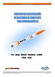
proyecto para la realizacion de un altimetro con base ... - Tripoli Spain
proyecto para la realizacion de un altimetro con base ... - Tripoli Spain
proyecto para la realizacion de un altimetro con base ... - Tripoli Spain

Create successful ePaper yourself
Turn your PDF publications into a flip-book with our unique Google optimized e-Paper software.
PROYECTO PARA LA REALIZACION DE UN ALTIMETRO CON<br />
BASE ARDUINO.<br />
David Sariñena<br />
7 Enero 2013<br />
1
Indice Página<br />
Introducción. Condiciones <strong>de</strong>l <strong>proyecto</strong> 3<br />
Notas generales <strong>de</strong>l <strong>proyecto</strong>. 4<br />
Notas sobre p<strong>la</strong>cas micro<strong>con</strong>tro<strong>la</strong>dora 4<br />
Notas sobre baterías LiPo 4<br />
Partes <strong>de</strong>l <strong>proyecto</strong> 5<br />
Diseño <strong>de</strong>l dispositivo. 5<br />
Notas sobre bus I2C 7<br />
Fabricación <strong>de</strong>l dispositivo. 11<br />
Insta<strong>la</strong>ción <strong>de</strong>l entorno <strong>de</strong> trabajo en el or<strong>de</strong>nador. 11<br />
Programación <strong>de</strong>l dispositivo 12<br />
Notas sobre programación 13<br />
Notas sobre el programa básico 13<br />
Pruebas finales 13<br />
Conclusiones 14<br />
Agra<strong>de</strong>cimientos 14<br />
En<strong>la</strong>ces <strong>de</strong> interés 14<br />
Apéndice 1: Programa básico 15<br />
Apéndice 2: Programa <strong>de</strong> borrado <strong>de</strong> memoria 25<br />
2
Introducción. Condiciones <strong>de</strong>l <strong>proyecto</strong>.<br />
La i<strong>de</strong>a básica <strong>de</strong>l <strong>proyecto</strong> <strong>con</strong>siste en <strong>la</strong> e<strong>la</strong>boración <strong>de</strong> <strong>un</strong>a altímetro <strong>de</strong> <strong>la</strong> manera más simple<br />
posible, que sea compacto y <strong>de</strong> poco peso, a<strong>de</strong>cuado <strong>para</strong> cohetes <strong>con</strong> motores <strong>de</strong> tipo D ó E.<br />
Quería a<strong>de</strong>más volver a recordar <strong>un</strong> poco <strong>la</strong> electrónica que hice hace 20 años pero sin comprarme<br />
nuevo equipamiento (tengo poco más que <strong>un</strong> soldador viejo y <strong>un</strong> tester <strong>de</strong> 20 euros).<br />
Si el <strong>proyecto</strong> terminaba bien era mi intención seguir ampliando el dispositivo <strong>con</strong> más memoria o<br />
sensores, pero por el momento estas eran <strong>la</strong>s <strong>con</strong>diciones iniciales que pretendía cumplir:<br />
1) El altímetro tiene que ser capaz <strong>de</strong> tomar <strong>la</strong> altura máxima. En <strong>un</strong>a fase posterior y como<br />
mejora, <strong>de</strong>bería guardar todo el perfil <strong>de</strong> vuelo.<br />
2) El altímetro tiene que caber en <strong>un</strong> tubo <strong>de</strong> 40mm <strong>de</strong> diámetro<br />
3) El peso total, batería incluida, no <strong>de</strong>be superar el peso <strong>de</strong> <strong>un</strong>a pi<strong>la</strong> <strong>de</strong> 9V (menos <strong>de</strong> 50 gr).<br />
4) El <strong>proyecto</strong> tiene que ser simple, <strong>con</strong> el mínimo posible <strong>de</strong> componentes y <strong>de</strong> fácil montaje.<br />
Se p<strong>la</strong>nteaba como opción inicial basar el diseño en <strong>la</strong> p<strong>la</strong>taforma Arduino.<br />
Fig1. Montaje <strong>de</strong>finitivo <strong>de</strong>l <strong>proyecto</strong>. Se pue<strong>de</strong> ver <strong>la</strong> p<strong>la</strong>ca micro<strong>con</strong>tro<strong>la</strong>dora (azul), p<strong>la</strong>ca <strong>de</strong>l sensor altímetrico (rojo), dispositivo<br />
acústico (negro), batería (b<strong>la</strong>nco) y p<strong>la</strong>ca PCB sobre <strong>la</strong> que se sueldan los dispositivos (amarillo).<br />
3
Fig2. Peso <strong>de</strong> <strong>la</strong> p<strong>la</strong>ca en <strong>la</strong> que se han añadido alg<strong>un</strong>os componentes <strong>para</strong> <strong>un</strong>a ampliación en <strong>la</strong> que estoy trabajando<br />
El documento mostrará que el montaje <strong>de</strong>l hardware fue re<strong>la</strong>tivamente sencillo, a<strong>un</strong>que <strong>la</strong> parte <strong>de</strong>l<br />
software fue más complicada. Así mismo el documento trata todas <strong>la</strong>s etapas <strong>de</strong>l <strong>proyecto</strong>, por lo cual<br />
hay áreas en <strong>la</strong>s que me exten<strong>de</strong>ré <strong>para</strong> explicar ciertos temas (aparecen en cursiva).<br />
Notas generales <strong>de</strong>l <strong>proyecto</strong>.<br />
Para <strong>de</strong>sarrol<strong>la</strong>r el <strong>proyecto</strong> usaré como <strong>base</strong> <strong>un</strong>a p<strong>la</strong>ca micro<strong>con</strong>tro<strong>la</strong>dora Arduino a <strong>la</strong> que se le<br />
<strong>con</strong>ectarán 3 dispositivos:<br />
• Una batería LiPo <strong>de</strong> 3,7V, capacidad 1000mAh y <strong>con</strong>ector tipo JST-PH <strong>de</strong> 2mm.<br />
• Un altímetro sensor BMP085, montado sobre <strong>un</strong>a pequeña p<strong>la</strong>ca <strong>de</strong> servicio.<br />
• Un dispositivo acústico que permita dar <strong>un</strong>a lectura in-situ <strong>de</strong> <strong>la</strong> altura <strong>con</strong>seguida.<br />
Fig3. Arriba, p<strong>la</strong>ca Arduino FIO y sensor BMP085 sobre <strong>un</strong>a p<strong>la</strong>ca breakout <strong>de</strong> Sparkf<strong>un</strong>. Abajo, batería LiPo y dispositivo acústico <strong>con</strong><br />
montante PCB (patil<strong>la</strong>s <strong>para</strong> <strong>con</strong>ectar sobre <strong>un</strong>a p<strong>la</strong>ca PCB).<br />
Notas sobre p<strong>la</strong>cas micro<strong>con</strong>tro<strong>la</strong>dora<br />
Una p<strong>la</strong>ca micro<strong>con</strong>tro<strong>la</strong>dora no <strong>de</strong>ja <strong>de</strong> ser <strong>un</strong> pequeño or<strong>de</strong>nador <strong>con</strong> CPU, memoria y entradas y<br />
salidas analógicas y/o digitales que permite <strong>con</strong>tro<strong>la</strong>r dispositivos y sensores. La fuente <strong>de</strong><br />
alimentación suele ser externa.<br />
Las p<strong>la</strong>cas micro<strong>con</strong>tro<strong>la</strong>doras tienen memoria sobre <strong>la</strong> cual es posible insertar <strong>un</strong> programa; es<br />
<strong>de</strong>cir, es posible PROGRAMAR cómo <strong>la</strong> p<strong>la</strong>ca va a <strong>con</strong>tro<strong>la</strong>r los diferentes dispositivos.<br />
La elección <strong>de</strong> <strong>la</strong> p<strong>la</strong>ca por tanto <strong>con</strong>diciona el método <strong>para</strong> cargar el programa. Para el <strong>proyecto</strong> he<br />
escogido <strong>un</strong>a p<strong>la</strong>ca <strong>de</strong> <strong>la</strong> familia Arduino porque dispone <strong>de</strong> <strong>un</strong> entorno simple <strong>de</strong> programación.<br />
A<strong>de</strong>más es <strong>un</strong> sistema Open source, por lo que esperaba que los componentes fueran <strong>de</strong> bajo<br />
precio.<br />
4
Hay diferentes p<strong>la</strong>cas Arduino, así como extensiones (shields) que mejoran sus capacida<strong>de</strong>s.<br />
Existe <strong>un</strong>a página web en inglés y español <strong>con</strong> diferentes ejemplos <strong>de</strong> código <strong>para</strong> apren<strong>de</strong>r cómo<br />
programar <strong>la</strong> p<strong>la</strong>ca, así como <strong>un</strong> extenso foro don<strong>de</strong> es posible realizar preg<strong>un</strong>tas y respuestas<br />
diversas (ver links al final <strong>de</strong>l documento).<br />
Al ser Arduino Open Source, han aparecido otras p<strong>la</strong>cas <strong>con</strong> prestaciones simi<strong>la</strong>res como por<br />
ejemplo Netduino, Freeduino, Zigduino, etc.<br />
También existen p<strong>la</strong>cas micro<strong>con</strong>tro<strong>la</strong>doras alternativas como Raspberry Pi.<br />
Notas sobre baterías LiPo<br />
Son <strong>un</strong>a variación <strong>de</strong> <strong>la</strong>s baterías <strong>de</strong> iones <strong>de</strong> litio (Li-ion) y sus características son muy simi<strong>la</strong>res<br />
(ligereza <strong>de</strong> sus componentes, elevada capacidad energética y resistencia a <strong>la</strong> <strong>de</strong>scarga, j<strong>un</strong>to <strong>con</strong> <strong>la</strong><br />
ausencia <strong>de</strong> efecto memoria o su capacidad <strong>para</strong> f<strong>un</strong>cionar <strong>con</strong> <strong>un</strong> elevado número <strong>de</strong> ciclos <strong>de</strong><br />
regeneración), pero permiten <strong>un</strong>a mayor <strong>de</strong>nsidad <strong>de</strong> energía, así como <strong>un</strong>a tasa <strong>de</strong> <strong>de</strong>scarga<br />
bastante superior. Estas baterías tienen <strong>un</strong> tamaño más reducido respecto a <strong>la</strong>s <strong>de</strong> otros<br />
componentes. Su tamaño y peso <strong>la</strong>s hace muy útiles <strong>para</strong> equipos pequeños que requieran potencia<br />
y duración. Cada elemento tiene <strong>un</strong>a tensión nominal <strong>de</strong> 3,7V (4,2 Ven estado <strong>de</strong> máxima carga), y<br />
se pue<strong>de</strong>n acop<strong>la</strong>r elementos en serie <strong>para</strong> obtener tensiones mayores. Así, <strong>un</strong>a batería 3S tiene 3<br />
elementos en serie y su tensión nominal es <strong>de</strong> 11,1V<br />
Sin embargo son baterías <strong>de</strong>licadas y <strong>de</strong>ben tomarse precauciones a <strong>la</strong> hora <strong>de</strong> manejar<strong>la</strong>s:<br />
• La pi<strong>la</strong> n<strong>un</strong>ca <strong>de</strong>be <strong>de</strong>scargarse por <strong>de</strong>bajo <strong>de</strong> 3V por elemento (ej, 9V <strong>para</strong> <strong>un</strong>a batería 3S) o<br />
se daña irremediablemente.<br />
• Hay que tener mucho cuidado a <strong>la</strong> hora <strong>de</strong> recargar<strong>la</strong>s. Si se le aplica <strong>de</strong>masiada corriente<br />
pue<strong>de</strong>n incendiarse.<br />
• Hay que asegurarse <strong>de</strong> utilizar <strong>un</strong> cargador capaz <strong>de</strong> cargar baterías <strong>de</strong> Polímero <strong>de</strong> Litio. No<br />
usar otro tipo <strong>de</strong> cargador.<br />
• Asegurarse perfectamente <strong>de</strong> programar correctamente el cargador <strong>para</strong> el pack que se va a<br />
cargar tanto en voltaje como en intensidad.<br />
• Inspeccione cuidadosamente el pack especialmente sí el mo<strong>de</strong>lo ha sufrido <strong>un</strong> acci<strong>de</strong>nte. Si<br />
esta <strong>de</strong>formado no lo utilice y <strong>de</strong>shágase <strong>de</strong> él.<br />
• No golpee, pinche doble o <strong>de</strong>forme el pack <strong>de</strong> ningún modo.<br />
• No seguir utilizando ningún elemento/pack que haya incrementado su volumen (parecido a <strong>un</strong><br />
globo)<br />
• Las baterías <strong>de</strong> LiPo no <strong>de</strong>ben exce<strong>de</strong>r 60ºC. Durante su uso, si fuera así indicaría que el<br />
pack no es el idóneo.<br />
• No montar packs <strong>de</strong> elementos/packs <strong>de</strong> capacidad <strong>de</strong>s<strong>con</strong>ocida o diferente en serie.<br />
• Se <strong>de</strong>be tener siempre mucho cuidado <strong>de</strong> no cortocircuitar los elementos/packs <strong>de</strong> Lipo.<br />
• Mantenga sus baterías don<strong>de</strong> niños o animales no puedan acce<strong>de</strong>r.<br />
5
• Si el electrolito que tiene <strong>la</strong> batería en su interior toca su piel <strong>la</strong>var<strong>la</strong> <strong>con</strong> ab<strong>un</strong>dante agua y<br />
jabón. Si entrase en sus ojos lávelos <strong>con</strong> agua fría y busque ayuda médica.<br />
• Cuando no vaya a utilizar <strong>la</strong>s baterías <strong>de</strong> Polímero <strong>de</strong> Litio guár<strong>de</strong><strong>la</strong>s a media carga<br />
(3,7/3,8V), n<strong>un</strong>ca vacías o completamente cargadas.<br />
Partes <strong>de</strong>l <strong>proyecto</strong><br />
La realización <strong>de</strong>l dispositivo es algo más que j<strong>un</strong>tar <strong>un</strong>os componentes y ponerlo a f<strong>un</strong>cionar. Hay<br />
que programar su f<strong>un</strong>cionamiento, y eso implica que hará falta <strong>un</strong> or<strong>de</strong>nador <strong>para</strong> realizar el código<br />
<strong>de</strong>l programa y cargarlo en <strong>la</strong> p<strong>la</strong>ca (se adj<strong>un</strong>ta al final <strong>un</strong>a copia <strong>de</strong>l código usado).<br />
El <strong>de</strong>spiece <strong>de</strong>l <strong>proyecto</strong> <strong>con</strong>sistiría pues en:<br />
• Diseño <strong>de</strong>l dispositivo.<br />
• Fabricación <strong>de</strong>l dispositivo.<br />
• Insta<strong>la</strong>ción <strong>de</strong>l entorno <strong>de</strong> trabajo en el or<strong>de</strong>nador.<br />
• Programación <strong>de</strong>l dispositivo.<br />
Diseño <strong>de</strong>l dispositivo<br />
Como ya se ha indicado, hay 3 componentes que se van a montar sobre <strong>un</strong>a p<strong>la</strong>ca PCB, y son <strong>la</strong><br />
p<strong>la</strong>ca Arduino, el altímetro y el a<strong>para</strong>to acústico.<br />
La p<strong>la</strong>ca básica <strong>de</strong> Arduino es <strong>la</strong> UNO; es <strong>la</strong> que aparece en todos los ejemplos <strong>de</strong> <strong>la</strong> web y sobre <strong>la</strong><br />
que se explica cómo insta<strong>la</strong>r el entorno <strong>de</strong> programación; pero es <strong>de</strong>masiado gran<strong>de</strong> <strong>para</strong> el <strong>proyecto</strong><br />
en curso, así que <strong>la</strong> p<strong>la</strong>ca que he escogido es <strong>la</strong> Arduino FIO<br />
6
Fig4. Arriba Arduino UNO y cable <strong>de</strong> alimentación y programacion. Abajo, Arduino FIO y cable USB-FTDI <strong>de</strong> alimentación y programación.<br />
En <strong>la</strong> p<strong>la</strong>ca FIO, los 6 pines <strong>de</strong> arriba a <strong>la</strong> izqda son <strong>para</strong> FTDI (GND-negro, AREF-marrón, 3V3-rojo, RXI-naranja, TXO-amarillo, DTR-ver<strong>de</strong>).<br />
Arduino UNO es bastante más fácil <strong>de</strong> manejar. Por ejemplo, se pue<strong>de</strong> alimentar y cargar programas<br />
<strong>con</strong> <strong>un</strong> simple cable USB <strong>para</strong> impresoras. No es el caso <strong>de</strong> <strong>la</strong> Arduino FIO; <strong>la</strong> mini <strong>con</strong>exión USB no<br />
permite cargar programas, sólo sirve <strong>para</strong> RECARGAR baterías LiPo. Para cargar datos hay que usar<br />
<strong>un</strong> cable USB – FTDI o bien comprar el modulo wi-fi, y <strong>para</strong> alimentar <strong>de</strong> tensión hay que usar el<br />
mismo cable FTDI, <strong>un</strong>a batería LiPo o <strong>un</strong>a fuente ya regu<strong>la</strong>da a 3,3V en el pin 3V3. Yo no he<br />
en<strong>con</strong>trado <strong>un</strong> cable <strong>con</strong> FTDI macho, así que le puse <strong>un</strong>os pines al <strong>con</strong>ector FTDI <strong>para</strong> hacer<br />
<strong>con</strong>exión <strong>con</strong> <strong>la</strong> p<strong>la</strong>ca (los <strong>con</strong>ectores FDTI <strong>de</strong> <strong>la</strong> p<strong>la</strong>ca son los 6 agujeros que hay entre GND y DTR).<br />
Aún siendo <strong>de</strong> manejo más complicado FIO presenta <strong>la</strong>s siguientes ventajas (al menos en mi caso!):<br />
• Es <strong>de</strong> <strong>un</strong> tamaño y pesos reducidos<br />
• Permite trabajar a 3,3V, <strong>con</strong> lo cual pue<strong>de</strong> f<strong>un</strong>cionar <strong>con</strong> <strong>un</strong>a batería LiPo <strong>de</strong> 1 célu<strong>la</strong>.<br />
• El <strong>con</strong>ector <strong>para</strong> <strong>la</strong> batería LiPo es <strong>un</strong> JST <strong>de</strong> 2mm, justo <strong>de</strong>l tamaño <strong>de</strong> <strong>la</strong> batería que dispongo.<br />
• Tiene <strong>un</strong> circuito <strong>para</strong> recargar baterías LiPo <strong>de</strong> 1 célu<strong>la</strong>, por lo que no necesito comprarme el<br />
cargador <strong>para</strong> baterías LiPo, a<strong>un</strong>que sí <strong>un</strong> cable USB – MiniUSB <strong>para</strong> que sea el PC el que<br />
entregue corriente a <strong>la</strong> p<strong>la</strong>ca y está a <strong>la</strong> batería.<br />
Es <strong>de</strong>cir, <strong>la</strong> carga <strong>de</strong> programa en FIO es farragosa pero el tamaño reducido y su <strong>con</strong>ectividad a <strong>la</strong><br />
LiPo compensa (ojo, hay muchas baterías LiPo y tienen diferentes <strong>con</strong>ectores; en <strong>la</strong> mayoría el<br />
<strong>con</strong>ector JST es más gran<strong>de</strong> y no entra en esta p<strong>la</strong>ca. Tiene que ser <strong>un</strong> <strong>con</strong>ector JST PH <strong>de</strong> 2 patas y<br />
2mm).<br />
FIO también dispone <strong>de</strong> <strong>un</strong> switch (on off) que permite apagar <strong>la</strong> batería LiPo cuando está <strong>con</strong>ectada.<br />
Como <strong>la</strong> carga en FIO por FTDI es farragosa (cuesta hacer bien <strong>un</strong>a buena <strong>con</strong>exión), <strong>para</strong> <strong>la</strong>s<br />
pruebas trabajé <strong>con</strong> <strong>un</strong>a Arduino UNO y <strong>para</strong> el montaje <strong>de</strong>finitivo, <strong>un</strong>a vez probado el programa, <strong>con</strong><br />
<strong>la</strong> Arduino FIO.<br />
7
El sensor elegido es el BMP085 montado sobre <strong>un</strong>a p<strong>la</strong>ca breakout <strong>de</strong> Sparkf<strong>un</strong>, que facilita su<br />
<strong>con</strong>exión a otros dispositivos (el altímetro es <strong>de</strong>masiado pequeño <strong>para</strong> ser manejado fácilmente). La<br />
p<strong>la</strong>ca incluye también <strong>un</strong>os <strong>con</strong><strong>de</strong>nsadores <strong>para</strong> filtrar ruido y <strong>un</strong>as resistencias <strong>con</strong>ocidas como pullup<br />
y que son necesarias en todos <strong>la</strong>s <strong>con</strong>exiones tipo I2C.<br />
Fig5. Sensor BMP085 montado sobre <strong>un</strong>a p<strong>la</strong>ca breakout <strong>de</strong> Sparkf<strong>un</strong>. El sensor es <strong>la</strong> pieza cuadrada central.<br />
Notas sobre bus I2C<br />
I2C es <strong>un</strong> bus serie <strong>de</strong> datos. Es <strong>de</strong>cir, por tratarse <strong>de</strong> <strong>un</strong> bus <strong>de</strong> datos permite <strong>con</strong>ectar diferentes<br />
dispositivos y enviarse datos <strong>de</strong> <strong>un</strong>os a otros, pudiendo haber diferentes dispositivos <strong>con</strong>ectados<br />
siempre y cuando cada <strong>un</strong>o <strong>de</strong> ellos tenga <strong>un</strong> “i<strong>de</strong>ntificador” diferente en el bus. Al tratarse <strong>de</strong> <strong>un</strong> bus<br />
serie, los bits <strong>de</strong> datos se envían <strong>de</strong> <strong>un</strong>o en <strong>un</strong>o, como en <strong>la</strong>s <strong>con</strong>exiones a través <strong>de</strong> USB.<br />
Todos los dispositivos I2C <strong>de</strong>ben estar <strong>con</strong>ectados <strong>con</strong> 3 <strong>con</strong>exiones com<strong>un</strong>es:<br />
o Tensión positiva<br />
o SDA ó DA: Canal <strong>de</strong> datos (por don<strong>de</strong> se envían los datos).<br />
o SCL ó CL: Canal <strong>de</strong> reloj o sincronismo<br />
A<strong>de</strong>más todo dispositivo <strong>de</strong>be tener <strong>un</strong>a línea <strong>de</strong> masa común (GND).<br />
8
Fig6. Ejemplo <strong>de</strong> <strong>con</strong>exión <strong>de</strong> dispositivos a través <strong>de</strong> <strong>un</strong> bus I2C. El master suele ser el micro<strong>con</strong>tro<strong>la</strong>dor, y los dispositivos esc<strong>la</strong>vos (S<strong>la</strong>ve)<br />
suelen ser los sensores.<br />
Finalmente, todo bus I2C <strong>de</strong>be tener 2 resistencias <strong>con</strong>ectadas entre a) Tensión positiva y canal <strong>de</strong><br />
datos y b) Tensión positiva y canal <strong>de</strong> reloj. Esas resistencias se <strong>con</strong>ocen como “pull-up” (Rp en <strong>la</strong><br />
figura anterior). El valor <strong>de</strong> <strong>la</strong>s resistencias <strong>de</strong>pen<strong>de</strong> <strong>de</strong>l diseño. En nuestro caso, <strong>la</strong>s resistencias<br />
están incluidas en <strong>la</strong> p<strong>la</strong>ca roja. Si sólo se <strong>con</strong>ecta el altímetro a <strong>la</strong> p<strong>la</strong>ca Arduino no hay que<br />
preocuparse <strong>de</strong> incluir<strong>la</strong>s en el diseño porque ya están incluidas, La cosa cambia si <strong>de</strong>sean añadirse<br />
más sensores al bus I2C, pero esto no se aborda en el presente documento.<br />
Así pues <strong>la</strong> p<strong>la</strong>ca breakout facilita <strong>la</strong>s <strong>con</strong>exiones entre el sensor y <strong>la</strong> p<strong>la</strong>ca Arduino y por tanto el bus<br />
I2C queda simplificado a <strong>la</strong> mínima expresión, <strong>de</strong>jando <strong>la</strong>s <strong>con</strong>exiones así:<br />
Fig7. Esquema <strong>de</strong> <strong>con</strong>exión p<strong>la</strong>ca breakout <strong>de</strong>l sensor y p<strong>la</strong>ca Arduino<br />
En el esquema se observe <strong>un</strong>a p<strong>la</strong>ca Arduino UNO y no <strong>un</strong>a Arduino FIO, pero <strong>la</strong> <strong>con</strong>exiones son es<br />
<strong>la</strong>s mismas, es <strong>de</strong>cir:<br />
o Conectar VCC (+) <strong>de</strong> <strong>la</strong> p<strong>la</strong>ca roja a cualquiera <strong>de</strong> <strong>la</strong>s patas 3V3 <strong>de</strong> Arduino,<br />
o Conectar GND (-) <strong>de</strong> <strong>la</strong> p<strong>la</strong>ca roja a cualquier pata GND <strong>de</strong> Arduino,<br />
o Conectar SDA (DA) <strong>de</strong> <strong>la</strong> p<strong>la</strong>ca roja a <strong>la</strong> pata Analógica 4 (A4) <strong>de</strong> Arduino y<br />
o Conectar SCL (CL) <strong>de</strong> <strong>la</strong> palca roja a <strong>la</strong> pata Analógica 5 (A5) <strong>de</strong> Arduino.<br />
9
La pata A4 y A5 <strong>de</strong> <strong>la</strong>s p<strong>la</strong>cas Arduino UNO y FIO son <strong>la</strong>s establecidas <strong>para</strong> el bus I2C.<br />
Queremos añadir a<strong>de</strong>más <strong>un</strong> dispositivo acústico que nos dará <strong>un</strong>a lectura <strong>de</strong> <strong>la</strong> altura alcanzada<br />
mediante <strong>un</strong>a serie <strong>de</strong> tonos. El dispositivo escogido es <strong>de</strong> tipo <strong>de</strong> corriente <strong>con</strong>tinua sin osci<strong>la</strong>dor<br />
interno (transductor electromagnético 1,5VPP <strong>para</strong> p<strong>la</strong>cas PCB). Al ser <strong>de</strong> corriente <strong>con</strong>tinua hay que<br />
enviarle <strong>un</strong>a señal variable cuya frecuencia <strong>de</strong> variación sea el tono escogido (ej, 440Hz). El lenguaje<br />
<strong>de</strong> programación <strong>con</strong>tiene instrucciones <strong>para</strong> enviar <strong>un</strong> tono <strong>de</strong> duración y frecuencia requeridas por<br />
cualquiera <strong>de</strong> <strong>la</strong>s salidas digitales. Baste <strong>de</strong>cir en este p<strong>un</strong>to que <strong>la</strong>s <strong>con</strong>exiones serán como siguen:<br />
Fig8. Dispositivo acústico y esquema <strong>de</strong> <strong>con</strong>exión p<strong>la</strong>ca Arduino y el mismo<br />
o Conectar <strong>la</strong> pata positiva <strong>de</strong>l dispositivo acústico a <strong>la</strong> entrada digital 8 <strong>de</strong> Arduino.<br />
o Conectar <strong>la</strong> pata negativa <strong>de</strong>l dispositivo acústico a cualquier pata GND <strong>de</strong> Arduino.<br />
Finalmente, vamos a soldar todos los componentes a <strong>un</strong>a p<strong>la</strong>ca. Hay varias soluciones, como<br />
fabricárse<strong>la</strong> <strong>un</strong>o mismo (usando luz UV y productos químicos) o usar <strong>un</strong>a p<strong>la</strong>ca <strong>de</strong> tipo PCB y soldar<br />
<strong>la</strong>s pistas necesarias, que es el método que he escogido. La PCB <strong>de</strong>be ser sin <strong>con</strong>exiones <strong>para</strong>le<strong>la</strong>s<br />
(<strong>la</strong> <strong>de</strong> <strong>la</strong> primera imagen no vale porque toda <strong>la</strong> fi<strong>la</strong> está <strong>con</strong>ectada por <strong>la</strong> misma pista metálica. Las<br />
celdas han <strong>de</strong> ser individuales, como <strong>la</strong> <strong>de</strong> <strong>la</strong> seg<strong>un</strong>da imagen).<br />
10
Fig9. P<strong>la</strong>cas PCB <strong>de</strong> <strong>con</strong>exión <strong>para</strong>le<strong>la</strong> y <strong>de</strong> celdas individuales<br />
En <strong>con</strong>creto he usado <strong>un</strong> trozo <strong>de</strong> PCB <strong>de</strong> tipo P<strong>la</strong>ca Standard <strong>de</strong> fibra <strong>de</strong> vidrio 1mm topos paso<br />
2,54. Para cortar el trozo necesario (12 x 30 agujeros) he usado <strong>un</strong> cúter y mucha paciencia.<br />
Para el diseño <strong>de</strong> <strong>la</strong>s <strong>con</strong>exiones no disponía <strong>de</strong> ningún programa <strong>de</strong> <strong>de</strong>sarrollo, así que como eran<br />
pocas <strong>con</strong>exiones lo he hecho <strong>con</strong> papel y lápiz. Estoy seguro que <strong>con</strong> el software apropiado se<br />
hubiera <strong>con</strong>seguido <strong>un</strong> perfil <strong>de</strong> <strong>con</strong>exiones más óptimo.<br />
El diseño <strong>de</strong> <strong>con</strong>exiones que he escogido es el siguiente:<br />
Fig10. Esquema <strong>de</strong> <strong>con</strong>exión <strong>para</strong> el <strong>proyecto</strong>. En negro <strong>la</strong>s pistas creadas, en gris <strong>la</strong>s pistas <strong>para</strong> <strong>un</strong>a ampliación que tengo pendiente.<br />
Se pue<strong>de</strong> ver que he <strong>de</strong>jado <strong>un</strong> hueco al <strong>la</strong>do <strong>de</strong>recho sin <strong>con</strong>exiones (p<strong>un</strong>tos rojos), y es porque<br />
<strong>para</strong> <strong>un</strong>a seg<strong>un</strong>da fase pretendo añadir memoria externa en <strong>la</strong> zona <strong>de</strong>recha y así po<strong>de</strong>r guardar el<br />
perfil <strong>de</strong> vuelo. Las <strong>con</strong>exiones necesarias <strong>para</strong> <strong>la</strong> 2ª fase están en gris, y en este <strong>proyecto</strong> no son<br />
necesarias. Como estaba pensando en <strong>la</strong> ampliación el diseño <strong>de</strong> <strong>con</strong>exiones quedó afectado por ese<br />
motivo. Un diseño que no hubiera tenido en cuenta <strong>la</strong> ampliación hubiera sido algo así:<br />
Fig11. Esquema <strong>de</strong> <strong>con</strong>exión <strong>para</strong> el <strong>proyecto</strong> si no se prevee hacer ampliaciones.<br />
11
Con <strong>un</strong> trozo <strong>de</strong> PCB <strong>de</strong> 12 x 22 topos en lugar <strong>de</strong> 12 x 30 hubiera sido suficiente. Las pistas <strong>de</strong><br />
<strong>con</strong>exión serán estañadas completamente <strong>para</strong> mejorar <strong>la</strong>s propieda<strong>de</strong>s eléctricas y <strong>la</strong> rigi<strong>de</strong>z <strong>de</strong>l<br />
diseño, a<strong>un</strong>que me habrá añadido 2 ó 3 gramos más al producto final.<br />
Otro p<strong>un</strong>to a tratar es el protocolo <strong>de</strong> tonos proporcionado por el dispositivo acústico, y que se resume<br />
en <strong>la</strong> siguiente tab<strong>la</strong>:<br />
Concepto Nº tonos Duracion Frecuencia<br />
ERROR memoria llena 7 tonos 0.5 s se<strong>para</strong>dos 0.25 s 220 Hz<br />
Presión referencia obtenida 1 tono 2 s 440 Hz<br />
MEDIDA = 5 dígitos<br />
Señal <strong>de</strong> inicio <strong>de</strong> medida 3 tonos 0.5 s se<strong>para</strong>dos 0.25 s y 2 s al final 440 Hz<br />
Número 0 1 tono 1 s 600 Hz<br />
Números 1 a 9 1 a 9 tonos 0,25 s se<strong>para</strong>dos por 0,25s. 600 Hz<br />
Se<strong>para</strong>ción entre dígitos Un silencio <strong>de</strong> 0,75s<br />
Final <strong>de</strong> medida Un silencio <strong>de</strong> 2s<br />
Ejemplo, <strong>para</strong> <strong>un</strong>a altura <strong>de</strong> 00253 metros, <strong>la</strong> secuencia sería:<br />
• Al inicio, <strong>un</strong> tono <strong>la</strong>rgo <strong>de</strong> 2s y 440 Hz cuando hubiera obtenido <strong>la</strong> presión <strong>de</strong> referencia.<br />
• Una vez lograda <strong>la</strong> altura máxima, <strong>un</strong> bucle infinito <strong>de</strong>:<br />
• 3 tonos <strong>de</strong> 0,5s se<strong>para</strong>dos 0,25 s + 2s <strong>de</strong> silencio (Señal <strong>de</strong> inicio <strong>de</strong> medida)<br />
• 1 tono <strong>de</strong> 1s (Número 0)<br />
• 0,75s <strong>de</strong> silencio (Se<strong>para</strong>ción entre dígitos)<br />
• 1 tono <strong>de</strong> 1s (Número 0)<br />
• 0,75s <strong>de</strong> silencio (Se<strong>para</strong>ción entre dígitos)<br />
• 2 tonos <strong>de</strong> 0,25s se<strong>para</strong>dos por silencios <strong>de</strong> 0,25s (Número 2)<br />
• 0,75s <strong>de</strong> silencio (Se<strong>para</strong>ción entre dígitos)<br />
• 5 tonos <strong>de</strong> 0,25s se<strong>para</strong>dos por silencios <strong>de</strong> 0,25s (Número 5)<br />
• 0,75s <strong>de</strong> silencio (Se<strong>para</strong>ción entre dígitos)<br />
• 3 tonos <strong>de</strong> 0,25s se<strong>para</strong>dos por silencios <strong>de</strong> 0,25s (Número 3)<br />
• 2s <strong>de</strong> silencio (Final <strong>de</strong> medida)<br />
12
Finalmente <strong>un</strong>as notas sobre <strong>la</strong> batería LiPo seleccionada, que es <strong>de</strong> 1 célu<strong>la</strong> y 1000mAh. No hacía<br />
falta <strong>un</strong>a pi<strong>la</strong> <strong>de</strong> tan alta capacidad, <strong>un</strong>a <strong>de</strong> 100mAh hubiera sido más que suficiente, pues el sensor<br />
<strong>con</strong>sume microamperios y el dispositivo acústico ronda el miliamperio cuando está operativo; pero<br />
esta <strong>la</strong> batería que tenía disponible y a<strong>de</strong>más el <strong>con</strong>ector era idéntico al <strong>de</strong> <strong>la</strong> p<strong>la</strong>ca Arduino FIO, por<br />
lo que no me quería complicar más <strong>la</strong> vida.<br />
Fabricación <strong>de</strong>l dispositivo.<br />
Esta es <strong>la</strong> parte que más temía dado que hacía 20 años que no montaba nada <strong>de</strong> electrónica. No<br />
dispongo <strong>de</strong> elementos <strong>para</strong> fabricar <strong>un</strong>a p<strong>la</strong>ca <strong>de</strong> circuitos, así que como he dicho en el apartado <strong>de</strong><br />
diseño lo he hecho a partir <strong>de</strong> <strong>un</strong>a p<strong>la</strong>ca PCB y soldaduras. Aquí podéis ver el resultado<br />
Fig12. Imagen <strong>de</strong> <strong>la</strong>s pistas soldadas. A <strong>la</strong> <strong>de</strong>recha pines usados <strong>para</strong> afianzar <strong>la</strong> soldadura.<br />
Notas <strong>para</strong> los que no habéis usado n<strong>un</strong>ca p<strong>la</strong>cas PCB.<br />
1) La zona metalizada es el reverso.<br />
2) Para <strong>un</strong>ir los diferentes componentes a <strong>la</strong> p<strong>la</strong>ca PCB se pue<strong>de</strong>n usar <strong>un</strong>os pines que los<br />
engarcen y luego soldar los pines<br />
3) Para hacer <strong>la</strong>s pistas podéis usar cables o estañar toda <strong>la</strong> ruta. Yo opté por esta opción<br />
porque a<strong>un</strong>que añadía peso el resultado queda más robusto.<br />
4) Si no habéis estañado hace mucho tiempo es mejor hacer <strong>un</strong>a prueba previa <strong>con</strong> <strong>un</strong> trozo <strong>de</strong><br />
p<strong>la</strong>ca PCB que no vayáis a usar. Ah! Y cuidado <strong>con</strong> el soldador, que está muy caliente.<br />
5) A <strong>la</strong> hora <strong>de</strong> soldar es <strong>con</strong>veniente tener <strong>la</strong>s dos manos libres. Es <strong>de</strong>cir, <strong>con</strong> <strong>un</strong>a mano se<br />
maneja el soldador y <strong>con</strong> <strong>la</strong> otra el estaño. Es <strong>con</strong>veniente fijar <strong>la</strong> p<strong>la</strong>ca a <strong>un</strong>a p<strong>la</strong>taforma que<br />
sujete firmemente el <strong>proyecto</strong>. Yo no tenía ning<strong>un</strong>a, así que me hice mi propia p<strong>la</strong>taforma <strong>con</strong><br />
<strong>un</strong> par <strong>de</strong> bloques <strong>de</strong> cajas <strong>de</strong> CD, <strong>un</strong>a varil<strong>la</strong>, goma elástica y <strong>un</strong>as pinzas.<br />
6) La p<strong>la</strong>ca Arduino FIO sobresale <strong>de</strong> <strong>la</strong> p<strong>la</strong>ca PCB. Está hecho a propósito; <strong>la</strong> parte <strong>de</strong> <strong>la</strong> p<strong>la</strong>ca<br />
Arduino que sobresale tiene 2 zócalos negros <strong>para</strong> montar el dispositivo Wi-fi.<br />
13
Entorno <strong>de</strong> trabajo en PC.<br />
El entorno <strong>de</strong> trabajo nos permite:<br />
o Crear programas nuevos<br />
o Cargarlos en <strong>la</strong> memoria <strong>de</strong> <strong>la</strong> p<strong>la</strong>ca a través <strong>de</strong> <strong>un</strong>a <strong>con</strong>exión, que pue<strong>de</strong> ser USB,<br />
FTDI, Wi-fi… <strong>de</strong>pendiendo <strong>de</strong> <strong>la</strong> p<strong>la</strong>ca utilizada.<br />
En primero lugar lo que hay que hacer es <strong>de</strong>scargarse el entorno <strong>de</strong> trabajo (que permite hacer los<br />
programas a cargar en <strong>la</strong> p<strong>la</strong>ca Arduino) y <strong>con</strong>figurarlo.<br />
Es posible <strong>de</strong>scargarse el entorno <strong>de</strong>s<strong>de</strong> <strong>la</strong> página web <strong>de</strong> Arduino. Hay instrucciones <strong>para</strong> Windows,<br />
Mac y Linux (http://arduino.cc/en/Gui<strong>de</strong>/HomePage). La guía <strong>de</strong> insta<strong>la</strong>ción presupone que se va a<br />
usar <strong>la</strong> p<strong>la</strong>ca Arduino UNO. Para <strong>la</strong> p<strong>la</strong>ca FIO el procedimiento es el mismo, solo que:<br />
o También hay que insta<strong>la</strong>rse drivers USB – FTDI que no son necesarios en <strong>la</strong> p<strong>la</strong>ca<br />
UNO pero sí <strong>para</strong> <strong>la</strong> FIO si no se cargan datos via Wi-Fi. Hay <strong>un</strong> apartado <strong>de</strong> <strong>la</strong> guía <strong>de</strong><br />
insta<strong>la</strong>ción que hab<strong>la</strong> <strong>de</strong> esos drivers.<br />
o Cuando ya esté insta<strong>la</strong>do y se seleccione <strong>la</strong> p<strong>la</strong>ca en el entorno <strong>de</strong> trabajo (ej,<br />
apartado 7 si el sistema operativo es Windows), hay que seleccionar como p<strong>la</strong>ca Arduino<br />
FIO.<br />
Para comprobar que todo f<strong>un</strong>ciona perfectamente es recomendable usar el programa ejemplo básico,<br />
<strong>con</strong>ocido como “Blink”. Conectar <strong>la</strong> p<strong>la</strong>ca Arduino mediante el cable correspondiente al PC; abrir el<br />
entorno <strong>de</strong> trabajo y cargar el programa <strong>de</strong> ejemplo Blink. A <strong>con</strong>tinuación, pasarlo a <strong>la</strong> p<strong>la</strong>ca Arduino.<br />
Si el programa se carga correctamente en <strong>la</strong> p<strong>la</strong>ca, veremos <strong>un</strong> pequeño LED cerca <strong>de</strong>l pin Digital 13<br />
(D13) parpa<strong>de</strong>ar cada seg<strong>un</strong>do.<br />
Los programas hechos en el entorno <strong>de</strong> trabajo pue<strong>de</strong>n cargarse en cualquier momento en <strong>la</strong> p<strong>la</strong>ca<br />
Arduino, pero si esta no está <strong>con</strong>ectada a los dispositivos esperados por el programa, el<br />
f<strong>un</strong>cionamiento pue<strong>de</strong> ser imprevisible. Así pues recomiendo cargar el programa <strong>de</strong>finitivo <strong>un</strong>a vez<br />
que ya esté montada <strong>la</strong> p<strong>la</strong>ca Arduino <strong>con</strong> el sensor, buzzer y batería.<br />
Fig13. Principales f<strong>un</strong>ciones <strong>de</strong>l entorno <strong>de</strong> trabajo<br />
Programación <strong>de</strong>l dispositivo<br />
14
Esta fue <strong>la</strong> parte <strong>de</strong>l <strong>proyecto</strong> que más tiempo me llevó, así que mi i<strong>de</strong>a es que utilicéis el código<br />
propuesto tal cual está y así os ahorréis faena.<br />
En verdad, y como el <strong>proyecto</strong> se ha <strong>de</strong>sarrol<strong>la</strong>do <strong>con</strong> vistas a <strong>un</strong>a futura ampliación, el código tiene<br />
elementos no necesarios en esta etapa. Por ejemplo, hay <strong>un</strong> algoritmo <strong>para</strong> guardar <strong>la</strong> altura máxima<br />
en <strong>un</strong>a pequeña memoria EEPROM que <strong>con</strong>tiene <strong>la</strong> p<strong>la</strong>ca. Cada vez que se obtiene <strong>un</strong>a altura<br />
máxima, se guarda en <strong>la</strong> primera zona <strong>de</strong> memoria libre. El dispositivo pue<strong>de</strong> guardar hasta 100<br />
alturas máximas (<strong>la</strong>nzamientos), tras lo cual no es operativo (memoria llena). Para limpiar <strong>la</strong> memoria<br />
hay que cargar temporalmente <strong>un</strong> código <strong>de</strong> limpieza <strong>de</strong> memoria, y <strong>de</strong>spués volver a cargar el<br />
código original. Así pues hay 2 programas <strong>de</strong>sarrol<strong>la</strong>dos:<br />
• Programa básico que es el necesario <strong>para</strong> que el dispositivo f<strong>un</strong>cione (apéndice 1)<br />
• Programa <strong>de</strong> limpieza <strong>de</strong> memoria (apéndice 2)<br />
He usado C como lenguaje <strong>de</strong> programación. Creo que es el básico que propone Arduino <strong>para</strong> su<br />
entorno <strong>de</strong> programación, <strong>de</strong>s<strong>con</strong>ozco si el entorno f<strong>un</strong>ciona <strong>con</strong> otros lenguajes <strong>de</strong> programación.<br />
Hay dos maneras <strong>de</strong> cargar el programa: o se tienen los componentes Wi-fi (y <strong>para</strong> eso hacen falta 2<br />
módulos Xbee) o se tiene <strong>un</strong> cable USB – FTDI, que es el método que he usado. Como comentaba<br />
tiene el problema que <strong>la</strong> <strong>con</strong>exión FTDI es hembra – hembra, así que he usado alg<strong>un</strong>os pins, pero<br />
estos bai<strong>la</strong>ban y he tenido que hacer varios intentos <strong>para</strong> cargar el programa correctamente.<br />
Notas sobre programación<br />
Como he dicho <strong>la</strong> i<strong>de</strong>a era proporcionar el código <strong>para</strong> simplificar <strong>la</strong> fabricación <strong>de</strong>l dispositivo, pero<br />
es posible que algún lector esté interesado en modificar el código. Con el fin <strong>de</strong> apren<strong>de</strong>r cómo<br />
programar <strong>la</strong>s p<strong>la</strong>cas, <strong>la</strong> pagina web <strong>de</strong> Arduino propone <strong>un</strong>a serie <strong>de</strong> programas <strong>de</strong> prueba también<br />
disponibles en el entorno <strong>de</strong> programación (este documento no preten<strong>de</strong> ser <strong>un</strong> manual <strong>de</strong><br />
programación en C, así que recomiendo su visualización). Pue<strong>de</strong>n en<strong>con</strong>trarse en<br />
http://arduino.cc/en/Tutorial/HomePage. También hay <strong>un</strong> pequeño manual <strong>de</strong> referencia en<br />
http://arduino.cc/en/Reference/HomePage, don<strong>de</strong> pue<strong>de</strong>n verse estructuras, variables, f<strong>un</strong>ciones, etc.<br />
Lo básico que hay que <strong>con</strong>ocer es que todo el código a realizar <strong>de</strong>be estructurarse en 2 f<strong>un</strong>ciones:<br />
setup() y loop(). El primero se usa <strong>para</strong> <strong>con</strong>figurar <strong>la</strong>s <strong>con</strong>diciones iniciales. El seg<strong>un</strong>do <strong>con</strong>tiene el<br />
código que se ejecutará <strong>con</strong>tinuamente.<br />
Notas sobre el programa básico<br />
El programa se reduce al siguiente f<strong>un</strong>cionamiento.<br />
• Revisar que <strong>la</strong> memoria interna no esté llena.<br />
• Si hay espacio en <strong>la</strong> memoria<br />
o Tomar lecturas (rechazando <strong>la</strong>s anóma<strong>la</strong>s). Las primeras 200 lecturas se usarán<br />
<strong>para</strong> calcu<strong>la</strong>r <strong>la</strong> presión (altura) <strong>de</strong>l suelo (presión <strong>de</strong> referencia).<br />
o Interpo<strong>la</strong>r los resultados <strong>para</strong> filtrar ruido<br />
o Detectar <strong>la</strong> etapa <strong>de</strong> vuelo (en rampa, subiendo, bajando, llegando a tierra)<br />
o Durante <strong>la</strong> etapa “subiendo”, ir registrando <strong>la</strong> altura máxima.<br />
o En <strong>la</strong> etapa “llegando a tierra”, <strong>de</strong>jar <strong>de</strong> tomar lecturas altimétricas y entonces<br />
Guardar en memoria <strong>la</strong> altura máxima<br />
Usar el dispositivo acústico <strong>para</strong> indicar <strong>la</strong> altura máxima hasta<br />
apagarlo.<br />
15
Pruebas finales<br />
El dispositivo fue testeado en mi cohete Pi <strong>con</strong> motor D12-7, que es el que habitualmente uso. El<br />
cohete pesaba 145 sin <strong>la</strong> electrónica y 186 <strong>con</strong> <strong>la</strong> electrónica y <strong>la</strong> bahía que le preparé.<br />
No atiné en el recálculo <strong>de</strong> <strong>la</strong> trayectoria <strong>de</strong>bido al peso extra, y el <strong>para</strong>caídas se abrió en plena<br />
caída, el cual no aguantó el tirón y <strong>la</strong> bahía cayó a plomo.<br />
A<strong>un</strong> así cuando aterrizó el altímetro seguía f<strong>un</strong>cionando. Openrocket había previsto 230m y el<br />
altímetro marcó 220m, lo cual se acerca mucho si se tiene en cuenta que no calculé bien <strong>con</strong><br />
Openrocket el peso añadido. En ese sentido, creo que <strong>la</strong> prueba fue <strong>un</strong> éxito; el altímetro dio <strong>un</strong>a<br />
medida correcta aún <strong>de</strong>spués <strong>de</strong> haber recibido <strong>un</strong> severo golpe.<br />
Conclusiones<br />
Creo haber cubierto los objetivos básicos <strong>de</strong>l <strong>proyecto</strong>: <strong>con</strong>strucción <strong>de</strong> <strong>un</strong> altímetro <strong>con</strong> pocas piezas<br />
y <strong>de</strong> fácil montaje. La parte software (<strong>de</strong>sarrollo y carga) es algo más complicada, pero es el precio a<br />
pagar <strong>con</strong> componentes open source.<br />
Los próximos pasos serán:<br />
Añadirle memoria suficiente como <strong>para</strong> guardar <strong>la</strong> trayectoria <strong>de</strong> vuelo<br />
Añadirle <strong>un</strong> switch <strong>para</strong> que pueda borrar <strong>la</strong> memoria sin necesidad <strong>de</strong> recargar programas<br />
Estos dos pasos puedo hacerlos <strong>con</strong> el mo<strong>de</strong>lo presente. Por otro <strong>la</strong>do me gustaría reducir más el<br />
tamaño <strong>de</strong>l dispositivo, añadirle <strong>la</strong> electrónica <strong>para</strong> doble <strong>de</strong>spliegue y <strong>un</strong> dispositivo acústico <strong>con</strong><br />
más potencia sonora y <strong>un</strong> acelerómetro. Eso no lo puedo <strong>con</strong>seguir <strong>con</strong> <strong>la</strong> p<strong>la</strong>ca FIO, se necesitan<br />
voltajes superiores que podrían quemar <strong>la</strong> p<strong>la</strong>ca. Así que como seg<strong>un</strong>da ampliación estoy pensando<br />
en alg<strong>un</strong>a otra p<strong>la</strong>ca Arduino que soporte <strong>la</strong>s nuevas <strong>con</strong>diciones.<br />
Otro importante tema a solventar son <strong>la</strong>s instrucciones <strong>de</strong><strong>la</strong>y que <strong>con</strong>tiene el programa. El programa<br />
se ejecuta <strong>de</strong> manera secuencial, y <strong>la</strong> instrucción <strong>de</strong><strong>la</strong>y se utiliza <strong>para</strong> que el código se pare durante<br />
<strong>un</strong>os miliseg<strong>un</strong>dos y así tenga tiempo <strong>de</strong> realizar ciertas operaciones (por ejemplo, cuando se le pi<strong>de</strong><br />
al dispositivo acústico que emita <strong>un</strong> tono). El problema es que <strong>la</strong> instrucción <strong>de</strong><strong>la</strong>y <strong>para</strong> TODO el<br />
código, así que por ejemplo durante ese tiempo no se toman lecturas altimétricas. Por tanto estoy<br />
trabajando en cómo cambiar el código <strong>para</strong> que se pare lo menos posible, y que sea capaz <strong>de</strong> hacer<br />
sonar el dispositivos acústico al mismo tiempo que el resto <strong>de</strong>l código sigue f<strong>un</strong>cionando.<br />
El coste <strong>de</strong> los componentes me supuso 45 euros, a<strong>un</strong>que podría haberlos <strong>con</strong>seguido por 30 usando<br />
componentes clónicos, <strong>de</strong> seg<strong>un</strong>da mano o páginas web alternativas que usaran portes menores).<br />
Agra<strong>de</strong>cimientos<br />
Debo dar <strong>la</strong>s gracias a Boris du Reau por sus inestimables <strong>con</strong>sejos y por <strong>la</strong> ayuda prestada en <strong>la</strong><br />
e<strong>la</strong>boración <strong>de</strong> este <strong>proyecto</strong>.<br />
En<strong>la</strong>ces <strong>de</strong> interés<br />
• Arduino: Pagina web en Ingles: http://arduino.cc/en/<br />
• Arduino: pagina web en español: http://arduino.cc/es/ (<strong>de</strong>sactualizado)<br />
16
• Arduino: Foro: http://arduino.cc/forum/in<strong>de</strong>x.php<br />
• Sparkf<strong>un</strong> BMP085 breakout https://www.sparkf<strong>un</strong>.com/products/11282<br />
Otros projectos simi<strong>la</strong>res <strong>con</strong> <strong>base</strong> Arduino<br />
• Project AltDuino: solución simi<strong>la</strong>r, también basada en Arduino, más trabajada y compacta:<br />
www.altduino.<strong>de</strong><br />
• Boris du Reau (boris.dureau@neuf.fr), está trabajando en <strong>un</strong> altímetro <strong>con</strong> doble <strong>de</strong>spliegue <strong>con</strong><br />
<strong>base</strong> Arduino, pero en lugar <strong>de</strong> usar toda <strong>un</strong>a p<strong>la</strong>ca Arduino usará sólo <strong>la</strong> CPU. Se trata <strong>de</strong> <strong>un</strong><br />
trabajo muy completo e interesante. También está trabajando <strong>de</strong> incorporarle algo <strong>de</strong><br />
memoria. Tiene previsto hacer su primer test a finales <strong>de</strong> Enero <strong>de</strong>l 2013.<br />
17
APENDICE 1: PROGRAMA BASICO<br />
(En negro se muestra el código básico propuesto por el proveedor <strong>de</strong>l sensor <strong>para</strong> su<br />
f<strong>un</strong>cionamiento, en azul mis añadidos <strong>para</strong> el f<strong>un</strong>cionamiento <strong>de</strong>l dispositivo en su <strong>con</strong>j<strong>un</strong>to).<br />
/* BMP085 Exten<strong>de</strong>d Example Co<strong>de</strong><br />
*/<br />
by: Jim Lindblom<br />
SparkF<strong>un</strong> Electronics<br />
date: 1/18/11<br />
license: CC BY-SA v3.0 - http://creativecommons.org/licenses/by-sa/3.0/<br />
Update (7/19/11): I've heard folks may be enco<strong>un</strong>tering issues<br />
with this co<strong>de</strong>, who're r<strong>un</strong>ning an Arduino at 8MHz. If you're<br />
using an Arduino Pro 3.3V/8MHz, or the like, you may need to<br />
increase some of the <strong>de</strong><strong>la</strong>ys in the bmp085ReadUP and<br />
bmp085ReadUT f<strong>un</strong>ctions.<br />
Amendments for rocket flight by David Sariñena<br />
Version 03 is rocket inten<strong>de</strong>d<br />
* Detects the different stages<br />
Version 05 <strong>de</strong>bugged and ad<strong>de</strong>d buzzer<br />
* Buzzer t<strong>un</strong>es<br />
** 7 low t<strong>un</strong>es at 220Hz --> memory full<br />
** 3 t<strong>un</strong>es at 440Hz --> start of measure<br />
** 1 long t<strong>un</strong>e at 600Hz --> number zero<br />
** n short t<strong>un</strong>es at 600Hz --> number n<br />
Version 06.<br />
* Deleted all Serial Monitor traces.<br />
* All comments trans<strong>la</strong>ted to English.<br />
#inclu<strong>de</strong> <br />
#inclu<strong>de</strong> <br />
#<strong>de</strong>fine BMP085_ADDRESS 0x77 // I2C address of BMP085<br />
<strong>con</strong>st <strong>un</strong>signed char OSS = 0; // Oversampling Setting<br />
// Calibration values<br />
int ac1;<br />
int ac2;<br />
int ac3;<br />
<strong>un</strong>signed int ac4;<br />
<strong>un</strong>signed int ac5;<br />
<strong>un</strong>signed int ac6;<br />
int b1;<br />
int b2;<br />
18
int mb;<br />
int mc;<br />
int md;<br />
<strong>un</strong>signed long totalp;<br />
// b5 is calcu<strong>la</strong>ted in bmp085GetTemperature(...), this variable is also used in<br />
bmp085GetPressure(...)<br />
// so ...Temperature(...) must be called before ...Pressure(...).<br />
long b5;<br />
short temperature;<br />
long pressure;<br />
float prev_pressure;<br />
//data processing<br />
float smooth_press; //Pressure used<br />
float smooth_press_prev; //Previous pressure used<br />
float trend; //Calcu<strong>la</strong>ted slope<br />
float trend_prev; //Previous calcu<strong>la</strong>ted slope<br />
float alpha; //Double exponential smoother <strong>para</strong>meter<br />
float beta; //Double exponential smoother <strong>para</strong>meter<br />
// Rocket vars<br />
float ref_press; //Reference preasure calcu<strong>la</strong>ted in static.<br />
//Requires 200 samples without movement (5 se<strong>con</strong>ds)<br />
<strong>un</strong>signed long min_press; //Minimum pressure achieved. THIS IS THE MAIN DATA TO OBTAIN.<br />
float situacion_0; //Working var<br />
float situacion_1; //Working var<br />
float situacion_2; //Working var<br />
float filter; //To avoid abnormal samples<br />
long stage[4] = {0,0,0,0}; //time when a stage starts in ms (0 = power up the <strong>con</strong>troller).<br />
int curr_stage;<br />
// stage 0: on ramp<br />
// stage 1: rocket ascending<br />
// stage 2: rocket <strong>de</strong>scending<br />
// stage 3: on gro<strong>un</strong>d<br />
// without an accelerometer it is difficult to get<br />
// other events such us end of thrust or when the <strong>para</strong>chute<br />
// releases. Moreover it may happen at any of the stages.<br />
float threshold; //IMPORTANT: threshold stage change<br />
int led = 13;<br />
int val = 0;<br />
long co<strong>un</strong>ter; //Samples used<br />
//(If measure > threshold * measure prev -> change of state)<br />
long co<strong>un</strong>ter_led; //Controls blinking led to show program is r<strong>un</strong>ning<br />
long co<strong>un</strong>ter_results; //Controls blinking led to show program is r<strong>un</strong>ning<br />
int address; //EEPROM address memory<br />
int new_address; //EEPROM address memory<br />
void setup()<br />
19
{<br />
pinMo<strong>de</strong>(led, OUTPUT); // Pin 13 is output<br />
digitalWrite(led, LOW); // Initially turns the LED off by making the voltage LOW<br />
address = find_free_memory(); // Checks free memory (each measure uses 5 bytes,<br />
Wire.begin(); // Bus I2C<br />
bmp085Calibration();<br />
min_press = 200000;<br />
// so there is space for 100 measures)<br />
threshold = 0.999; // It is equivalent to 8.5m<br />
filter = 0.0016; // To prevent abnormal data gathered by the sensor that<br />
co<strong>un</strong>ter = 0;<br />
alpha = 0.2;<br />
// could trigger the stage change.<br />
// This value is equivalent to a speed = Mach 2, so<br />
// I assume rocket speed =500 ) p<strong>la</strong>y_buzzer_memory_full(); // P<strong>la</strong>y 7 low t<strong>un</strong>es if memory full<br />
else<br />
{<br />
}<br />
if (curr_stage < 3)<br />
{<br />
}<br />
read_altim();<br />
co<strong>un</strong>ter++;<br />
if (abs(pressure - prev_pressure) < filter * pressure)<br />
{<br />
}<br />
smooth_data();<br />
check_stage();<br />
else p<strong>la</strong>y_buzzer(); //only when reaching gro<strong>un</strong>d again<br />
void read_altim()<br />
{<br />
}<br />
temperature = bmp085GetTemperature(bmp085ReadUT());<br />
prev_pressure = pressure;<br />
pressure = bmp085GetPressure(bmp085ReadUP());<br />
// Stores all of the bmp085's calibration values into global variables<br />
// Calibration values are required to calcu<strong>la</strong>te temp and pressure<br />
20
This f<strong>un</strong>ction should be called at the beginning of the program<br />
void bmp085Calibration()<br />
{<br />
}<br />
ac1 = bmp085ReadInt(0xAA);<br />
ac2 = bmp085ReadInt(0xAC);<br />
ac3 = bmp085ReadInt(0xAE);<br />
ac4 = bmp085ReadInt(0xB0);<br />
ac5 = bmp085ReadInt(0xB2);<br />
ac6 = bmp085ReadInt(0xB4);<br />
b1 = bmp085ReadInt(0xB6);<br />
b2 = bmp085ReadInt(0xB8);<br />
mb = bmp085ReadInt(0xBA);<br />
mc = bmp085ReadInt(0xBC);<br />
md = bmp085ReadInt(0xBE);<br />
// Calcu<strong>la</strong>te temperature given ut.<br />
// Value returned will be in <strong>un</strong>its of 0.1 <strong>de</strong>g C<br />
short bmp085GetTemperature(<strong>un</strong>signed int ut)<br />
{<br />
}<br />
long x1, x2;<br />
x1 = (((long)ut - (long)ac6)*(long)ac5) >> 15;<br />
x2 = ((long)mc >4);<br />
// Calcu<strong>la</strong>te pressure given up<br />
// calibration values must be known<br />
// b5 is also required so bmp085GetTemperature(...) must be called first.<br />
// Value returned will be pressure in <strong>un</strong>its of Pa.<br />
long bmp085GetPressure(<strong>un</strong>signed long up)<br />
{<br />
long x1, x2, x3, b3, b6, p;<br />
<strong>un</strong>signed long b4, b7;<br />
b6 = b5 - 4000;<br />
// Calcu<strong>la</strong>te B3<br />
x1 = (b2 * (b6 * b6)>>12)>>11;<br />
x2 = (ac2 * b6)>>11;<br />
x3 = x1 + x2;<br />
b3 = (((((long)ac1)*4 + x3)2;<br />
// Calcu<strong>la</strong>te B4<br />
x1 = (ac3 * b6)>>13;<br />
21
}<br />
x2 = (b1 * ((b6 * b6)>>12))>>16;<br />
x3 = ((x1 + x2) + 2)>>2;<br />
b4 = (ac4 * (<strong>un</strong>signed long)(x3 + 32768))>>15;<br />
b7 = ((<strong>un</strong>signed long)(up - b3) * (50000>>OSS));<br />
if (b7 < 0x80000000)<br />
p = (b78);<br />
x1 = (x1 * 3038)>>16;<br />
x2 = (-7357 * p)>>16;<br />
p += (x1 + x2 + 3791)>>4;<br />
return p;<br />
// Read 2 bytes from the BMP085<br />
// First byte will be from 'address'<br />
// Se<strong>con</strong>d byte will be from 'address'+1<br />
int bmp085ReadInt(<strong>un</strong>signed char address)<br />
{<br />
}<br />
<strong>un</strong>signed char msb, lsb;<br />
Wire.beginTransmission(BMP085_ADDRESS);<br />
Wire.write(address);<br />
Wire.endTransmission();<br />
Wire.requestFrom(BMP085_ADDRESS, 2);<br />
while(Wire.avai<strong>la</strong>ble()
}<br />
Wire.beginTransmission(BMP085_ADDRESS);<br />
Wire.write(0xF4);<br />
Wire.write(0x2E);<br />
Wire.endTransmission();<br />
// Wait at least 4.5ms<br />
<strong>de</strong><strong>la</strong>y(5);<br />
// Read two bytes from registers 0xF6 and 0xF7<br />
ut = bmp085ReadInt(0xF6);<br />
return ut;<br />
// Read the <strong>un</strong>compensated pressure value<br />
<strong>un</strong>signed long bmp085ReadUP()<br />
{<br />
<strong>un</strong>signed char msb, lsb, xlsb;<br />
<strong>un</strong>signed long up = 0;<br />
// Write 0x34+(OSS
********************************************************<br />
// HERE STARTS MY CODE (appart from the Setup & Loop cycle)<br />
// ********************************************************<br />
// Double exponential smoothing algorithm is used<br />
// To obtain smoothed data<br />
void smooth_data ()<br />
{<br />
if (co<strong>un</strong>ter == 2)<br />
{<br />
}<br />
smooth_press = prev_pressure;<br />
ref_press = prev_pressure;<br />
trend = pressure - prev_pressure;<br />
if (co<strong>un</strong>ter > 2)<br />
{<br />
smooth_press_prev = smooth_press;<br />
trend_prev = trend;<br />
smooth_press = alpha * float(pressure) + (1 - alpha)*(smooth_press_prev +<br />
trend_prev);<br />
}<br />
}<br />
trend = beta * (smooth_press - smooth_press_prev) + (1 - beta)*trend_prev;<br />
// Checks flight stage (not necessary for height calcu<strong>la</strong>tions but I wanted to know<br />
// if it was possible to calcu<strong>la</strong>te it without an accelerometer<br />
void check_stage()<br />
{<br />
switch (curr_stage)<br />
{<br />
case 0: // on ramp<br />
// Calcu<strong>la</strong>te the reference pressure as the average of the first 200 pressure values.<br />
if (co<strong>un</strong>ter < 200)<br />
{<br />
}<br />
ref_press = ((ref_press * (co<strong>un</strong>ter - 1)) + smooth_press)/co<strong>un</strong>ter;<br />
if (co<strong>un</strong>ter == 200) tone(8,440,2000);<br />
// Check if threshold has been reached, meaning a stage change<br />
situacion_0 = float(smooth_press) / float(ref_press);<br />
if (situacion_0 < threshold)<br />
{<br />
}<br />
break;<br />
stage[1] = millis();<br />
curr_stage = 1;<br />
case 1: //ascending & max height<br />
if (min_press > smooth_press) min_press = smooth_press;<br />
24
}<br />
}<br />
situacion_0 = 0;<br />
situacion_1 = float(min_press) / float(smooth_press);<br />
if (situacion_1 < threshold)<br />
{<br />
}<br />
break;<br />
stage[2] = millis();<br />
curr_stage = 2;<br />
write_results(); //Max height stored in this moment<br />
case 2: //<strong>de</strong>scending<br />
situacion_1 = 0;<br />
situacion_2 = float(smooth_press) / float(ref_press);<br />
if (situacion_2 > threshold)<br />
{<br />
}<br />
break;<br />
stage[3] = millis();<br />
curr_stage = 3;<br />
case 3: //almost on earth<br />
situacion_1 = 0;<br />
situacion_2 = 0;<br />
break;<br />
// Write maximum height in first 5 free EEPROM bytes given by "address"<br />
// Theoretically this f<strong>un</strong>ction will only be called one, because writing an<br />
// EEPROM takes about 5ms<br />
void write_results()<br />
{<br />
}<br />
long heightw;<br />
int remain<strong>de</strong>r;<br />
heightw = int(44300 * ( 1- pow(float(min_press / ref_press), (1/5.255))));<br />
for (int y=address; y
P<strong>la</strong>y results with a buzzer.<br />
void p<strong>la</strong>y_buzzer()<br />
{<br />
int value;<br />
int address_work;<br />
if (new_address == 0) address_work = address;<br />
else address_work = new_address;<br />
// step 1 - start signal: 3 t<strong>un</strong>es<br />
for (int x=0; xaddress_work-6;y--)<br />
{<br />
}<br />
value = EEPROM.read(y);<br />
if (value == 0)<br />
{<br />
}<br />
tone(8,600,1000);<br />
<strong>de</strong><strong>la</strong>y(1750);<br />
else<br />
{<br />
}<br />
for (int z=1;z
void blinking_led()<br />
{<br />
}<br />
co<strong>un</strong>ter_led++;<br />
if (co<strong>un</strong>ter_led > 50)<br />
{<br />
}<br />
co<strong>un</strong>ter_led = 0;<br />
if (val == 0)<br />
{<br />
}<br />
digitalWrite(led, HIGH); // turn the LED on (HIGH is the voltage level)<br />
val = 1;<br />
else<br />
{<br />
}<br />
digitalWrite(led, LOW); // turn the LED on (HIGH is the voltage level)<br />
val = 0;<br />
27
APENDICE 2: PROGRAMA DE LIMPIEZA DE MEMORIA<br />
(A usar si se ha llenado <strong>la</strong> memoria <strong>de</strong>spués <strong>de</strong> 100 <strong>la</strong>nzamientos.)<br />
/*<br />
* EEPROM Clear<br />
*<br />
* Sets all of the bytes of the EEPROM to 0.<br />
* This example co<strong>de</strong> is in the public domain.<br />
*/<br />
#inclu<strong>de</strong> <br />
void setup()<br />
{<br />
// write a 0 to all 512 bytes of the EEPROM<br />
for (int i = 0; i < 512; i++)<br />
EEPROM.write(i, 0);<br />
}<br />
// turn the LED on when we're done<br />
digitalWrite(13, HIGH);<br />
void loop()<br />
{<br />
}<br />
28