4_10_PFEIFER_Sistema de barras 860_08_2002.pdf
4_10_PFEIFER_Sistema de barras 860_08_2002.pdf
4_10_PFEIFER_Sistema de barras 860_08_2002.pdf

Create successful ePaper yourself
Turn your PDF publications into a flip-book with our unique Google optimized e-Paper software.
SEILBAU ■ CABLE STRUCTURES<br />
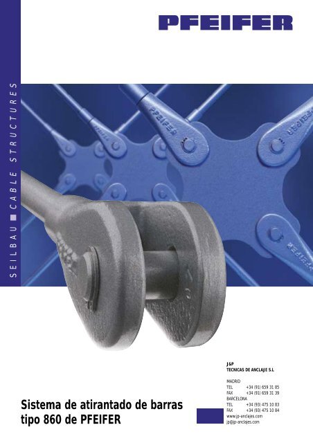
<strong>Sistema</strong> <strong>de</strong> atirantado <strong>de</strong> <strong>barras</strong><br />
tipo <strong>860</strong> <strong>de</strong> <strong>PFEIFER</strong><br />
J&P<br />
TECNICAS DE ANCLAJE S.L<br />
MADRID<br />
TEL +34 (91) 659 31 85<br />
FAX +34 (91) 659 31 39<br />
BARCELONA<br />
TEL +34 (93) 475 <strong>10</strong> 83<br />
FAX +34 (93) 475 <strong>10</strong> 84<br />
www.jp-anclajes.com<br />
jp@jp-anclajes.com
2<br />
Messehalle 9<br />
Hannover<br />
Neue Aufnahme.<br />
Winkel und Perspektive wie Abb. Seilzugglie<strong>de</strong>r<br />
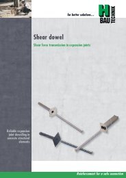
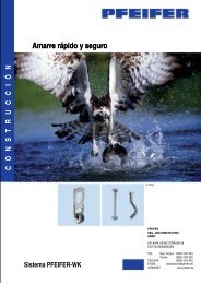
<strong>PFEIFER</strong> presenta:<br />
■ El sistema <strong>de</strong> atirantado<br />
<strong>de</strong> <strong>barras</strong> tipo <strong>860</strong> que<br />
combina estética y altas<br />
prestaciones<br />
Con Homologación <strong>de</strong> la Construcción que incluye<br />
certificado <strong>de</strong>:<br />
• Elementos <strong>de</strong> compresión<br />
• Terminales <strong>de</strong> cables<br />
<strong>Sistema</strong> <strong>de</strong> atirantado completo mediante <strong>barras</strong><br />
<strong>de</strong> alta calidad y estética<br />
Amplias prestaciones:<br />
• Diámetros <strong>de</strong> barra <strong>de</strong> <strong>10</strong> a <strong>10</strong>0 mm<br />
• Longitu<strong>de</strong>s <strong>de</strong> barra hasta 15 m<br />
Barras <strong>de</strong> alta resistencia con cargas admisibles<br />
<strong>de</strong> hasta 2.900 kN<br />
Elementos esbeltos y económicos<br />
Gran<strong>de</strong>s tolerancias<br />
Elementos galvanizados<br />
en caliente<br />
Con diversos accesorios<br />
<strong>de</strong> gran utilidad
Eficacia y<br />
experiencia<br />
Los tirantes <strong>PFEIFER</strong> se han empleado con muy<br />
buenos resultados en numerosas obras en todo el mundo.<br />
Con la Homologación <strong>de</strong>l Instituto Alemán <strong>de</strong> la<br />
Construcción en Berlín hemos simplificado aún más su<br />
implantación. La colocación <strong>de</strong> los tirantes es ahora<br />
posible sin llevar a cabo los largos y costosos procesos<br />
<strong>de</strong> aceptación.<br />
Los numerosos <strong>de</strong>talles <strong>de</strong> las uniones y su cuidada<br />
apariencia permiten encontrar una solución a<strong>de</strong>cuada<br />
para cualquier aplicación.<br />
Con los tirantes <strong>PFEIFER</strong>, in<strong>de</strong>pendientemente <strong>de</strong><br />
que el diseño se resuelva con cables o <strong>barras</strong>, usted<br />
contará con la experiencia y la seguridad <strong>de</strong> los lí<strong>de</strong>res<br />
<strong>de</strong>l mercado.<br />
El programa <strong>de</strong> atirantado mediante cables:<br />
Cabezal<br />
tipo 802<br />
Cabezal en acero<br />
inoxidable tipo 961<br />
Terminal roscado<br />
tipo 968<br />
1<br />
2<br />
3<br />
1<br />
2<br />
3<br />
Palacio <strong>de</strong> Exposiciones 9,<br />
Hannover<br />
Boehringer,<br />
Ingelheim<br />
Pasarela SAP,<br />
Walldorf<br />
3
4<br />
Los tirantes <strong>PFEIFER</strong> pue<strong>de</strong>n emplearse<br />
<strong>de</strong> manera económica en diversos ámbitos<br />
<strong>de</strong> la ingeniería, como por ejemplo:<br />
■ Atirantado <strong>de</strong> celosías<br />
■ Atirantado posterior <strong>de</strong> fachadas<br />
■ Tirantes en pilares <strong>de</strong> puentes<br />
■ Atirantado <strong>de</strong> cubiertas<br />
■ <strong>Sistema</strong>s articulados<br />
Permiten un diseño esbelto y estético y pue<strong>de</strong>n combinarse con los materiales <strong>de</strong> la<br />
arquitectura mo<strong>de</strong>rna – vidrio y ma<strong>de</strong>ra – en infinidad <strong>de</strong> aplicaciones.<br />
El principio <strong>de</strong> la transmisión <strong>de</strong> cargas <strong>de</strong> tracción y compresión ofrece al calculista<br />
múltiples ventajas en el dimensionamiento, y permite al arquitecto un diseño con<br />
interesantes formas.<br />
Atirantado <strong>de</strong> pilares<br />
Tirante inferior<br />
Cruz <strong>de</strong> S. Andrés
La técnica<br />
El sistema <strong>de</strong> atirantado <strong>PFEIFER</strong> tipo <strong>860</strong> se compone <strong>de</strong> la barra, los cabezales y<br />
sus componentes. Pue<strong>de</strong>n también suministrarse elementos especiales adicionales.<br />
El cálculo <strong>de</strong>l sistema <strong>de</strong> atirantado <strong>PFEIFER</strong> tipo <strong>860</strong> se realiza según la DIN 18800<br />
Parte 1/11.90. El dimensionamiento se confirma con un control a<strong>de</strong>cuado.<br />
Barras<br />
El material <strong>de</strong> la barra es acero S460N con un límite elástico mínimo <strong>de</strong> 460 N/mm2, es <strong>de</strong>cir un 30%<br />
superior al <strong>de</strong>l acero S355. Por lo tanto a igualdad <strong>de</strong> cargas los diámetros necesarios se reducen, por<br />
lo que aumentan la esbeltez y la economía.<br />
Las cargas admisibles están tabuladas en el catálogo y <strong>de</strong>ben ser iguales o superiores a los axiles<br />
actuantes mayorados obtenidos por cálculo (F d). Como elementos <strong>de</strong> unión se disponen discos y placas<br />
<strong>de</strong> anclaje en acero S355. Las dimensiones indicadas garantizan la capacidad <strong>de</strong> carga total correspondiente<br />
al límite elástico (N R,d). En caso <strong>de</strong> que las placas se fabriquen en acero S235, la capacidad <strong>de</strong><br />
carga se reduce al valor tabulado como N R,d,red.<br />
Componentes<br />
En el sistema <strong>de</strong> atirantado, la barra es el elemento más débil, ya que el diseño <strong>de</strong> los cabezales, bulones<br />
y manguitos garantiza mayores capacida<strong>de</strong>s <strong>de</strong> carga para evitar fallos en dichos componentes. El<br />
suministro incluye una contratuerca para unir tanto cabezales como manguitos a las <strong>barras</strong> correspondientes,<br />
bloqueando la rosca y materializando una estética transición entre los elementos <strong>de</strong> tamaños<br />
diferentes, cabezal o manguito y barra.<br />
Elementos especiales<br />
Como piezas especiales pue<strong>de</strong>n también suministrarse <strong>barras</strong> <strong>de</strong> compresión y cables, dotados <strong>de</strong> su<br />
correspondiente certificación<br />
Tolerancias <strong>de</strong> ajuste<br />
Gracias al roscado <strong>de</strong>recha-izquierda <strong>de</strong> los cabezales, es posible conseguir una regulación hasta la longitud<br />
exacta, no siendo posible un postesado. Con el sistema es posible conseguir una tolerancia <strong>de</strong><br />
aproximadamente 1,4 veces el diámetro <strong>de</strong> la barra para todos los tamaños y longitu<strong>de</strong>s. La longitud <strong>de</strong>l<br />
sistema es la distancia entre centros <strong>de</strong> bulones <strong>de</strong> cabezal.<br />
Protección contra la corrosión.<br />
Todos los elementos <strong>de</strong>l sistema <strong>de</strong> atirantado <strong>PFEIFER</strong> tipo <strong>860</strong> se suministran galvanizados en caliente<br />
según DIN EN ISO 1461 o zincados según DIN EN 22063. Las roscas se reperfilan tras el zincado.<br />
5
6<br />
H<br />
H<br />
E F<br />
E F<br />
I<br />
SFb<br />
Lgew<br />
SFb<br />
tGL<br />
G<br />
C<br />
B<br />
G<br />
C<br />
B<br />
SW<br />
Ma<br />
dB<br />
dB<br />
M<br />
L<br />
SW<br />
IM<br />
cmin<br />
A<br />
M<br />
A<br />
M<br />
D<br />
LA<br />
fmin<br />
BOHR<br />
D<br />
Barras<br />
Mat. S460N<br />
M<br />
mm<br />
NR,d* kN<br />
NR,d,red** kN<br />
Lgew mm<br />
SFb<br />
mm<br />
SW<br />
mm<br />
Lmax mm<br />
Peso<br />
kg/m<br />
<strong>10</strong> 26,3 26,3 33 <strong>10</strong> 9 6000 0,61<br />
12 38,3 38,3 38 12 <strong>10</strong> 6000 0,88<br />
16 71,2 60,1 54 15 14 15000 1,58<br />
20 111 93,9 67 18 18 15000 2,47<br />
24 160 160 80 23 22 15000 3,55<br />
27 2<strong>08</strong> 167 90 23 25 15000 4,50<br />
30 254 254 <strong>10</strong>0 28 28 15000 5,55<br />
36 371 260 120 28 33 15000 8,00<br />
42 509 359 140 33 39 15000 <strong>10</strong>,9<br />
48 669 488 159 38 45 15000 14,2<br />
52 798 638 172 43 49 15000 16,7<br />
56 922 638 187 43 53 15000 19,3<br />
60 <strong>10</strong>73 807 199 48 57 15000 22,2<br />
64 1215 997 211 53 60 15000 25,3<br />
70 1463 1206 233 58 65 15000 30,2<br />
80 19<strong>10</strong> 1685 266 68 75 15000 39,5<br />
90 2418 2243 297 78 85 15000 49,9<br />
<strong>10</strong>0 2985 2552 328 83 95 15000 61,7<br />
Salvo posibles modificaciones *Límite elástico según DIN 18800, Placa <strong>de</strong> anclaje S355J2G3 ** Placa <strong>de</strong> anclaje S235J2G3<br />
Cabezal<br />
Cabezal Bulón Contra- Placa <strong>de</strong> anclaje Peso<br />
Mat. EN-GJS-400-18-LT 34CrNiMo6V tuerca S355J2G3 y S235J2G3 total<br />
M<br />
mm<br />
A<br />
mm<br />
B<br />
mm<br />
C<br />
mm<br />
D<br />
mm<br />
E<br />
mm<br />
F<br />
mm<br />
H<br />
mm<br />
dB mm<br />
G<br />
mm<br />
lM mm<br />
tGL mm<br />
fmin mm<br />
cmin mm<br />
BOHR<br />
mm kg<br />
<strong>10</strong> 25 <strong>10</strong> 20 <strong>10</strong> 19 16 52 9 27,0 21 8 16 25 <strong>10</strong> 0,12<br />
12 29 12 24 11 21 18 58 <strong>10</strong> 31,0 25 <strong>10</strong> 17 29 11 0,20<br />
16 42 15 32 15 30 26 77 14 41,0 33 12 23 42 15 0,53<br />
20 52 18 40 17 35 31 93 16 50,2 41 15 27 52 17 0,95<br />
24 58 23 48 23 46 39 115 22 59,8 49 20 36 58 23 1,57<br />
27 68 23 54 25 47 44 125 24 66,6 55 20 39 68 25 2,34<br />
30 77 28 60 29 52 51 138 28 74,8 62 25 47 77 29 3,14<br />
36 90 28 72 33 64 58 167 32 89,3 74 25 53 90 33 5,57<br />
42 <strong>10</strong>4 33 84 37 70 66 190 36 <strong>10</strong>3 86 30 59 <strong>10</strong>4 37 8,74<br />
48 120 38 96 41 78 74 213 40 118 99 35 66 120 41 12,7<br />
52 136 43 <strong>10</strong>4 46 85 84 231 45 126 <strong>10</strong>7 40 73 136 46 16,5<br />
56 148 43 112 51 95 91 254 50 138 115 40 81 148 51 21,9<br />
60 162 48 120 56 <strong>10</strong>6 <strong>10</strong>0 275 55 146 124 45 90 162 56 27,1<br />
64 170 53 128 56 <strong>10</strong>7 <strong>10</strong>3 286 55 154 132 50 90 170 56 31,6<br />
70 185 58 140 61 117 113 315 60 166 144 55 98 185 61 39,3<br />
80 2<strong>10</strong> 68 160 71 133 132 359 70 187 165 65 114 2<strong>10</strong> 71 58,6<br />
90 240 78 180 80 150 150 402 79 211 185 75 128 240 80 85,5<br />
<strong>10</strong>0 265 83 200 90 170 165 448 89 232 205 80 144 265 90 120,5<br />
Excepto posibles modificaciones<br />
Cabezal con adaptador<br />
Cabezal Bulón Contra- Adaptador Peso<br />
Mat. EN-GJS-400-18-LT 34CrNiMo6V tuerca S460N total<br />
M A B C D E F H d B G l M LA L Ma SW SFb<br />
mm mm mm mm mm mm mm mm mm mm mm mm mm mm mm mm kg<br />
<strong>10</strong> 25 <strong>10</strong> 20 <strong>10</strong> 19 16 52 9 27,0 21 50 <strong>10</strong>5 15 12 6 0,19<br />
12 29 12 24 11 21 18 58 <strong>10</strong> 31,0 25 60 122 18 14 7 0,32<br />
16 42 15 32 15 30 26 77 14 41,0 33 80 161 24 19 <strong>10</strong> 0,82<br />
20 52 18 40 17 35 31 93 16 50,2 41 <strong>10</strong>0 198 30 24 12 1,52<br />
24 58 23 48 23 46 39 115 22 59,8 49 115 236 37 30 14 2,57<br />
27 68 23 54 25 47 44 125 24 66,6 55 130 261 41 32 16 3,73<br />
30 77 28 60 29 52 51 138 28 74,8 62 140 285 45 36 18 4,95<br />
36 90 28 72 33 64 58 167 32 89,3 74 170 345 54 46 22 8,75<br />
Excepto posibles modificaciones
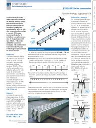
<strong>Sistema</strong> <strong>de</strong> atirantado<br />
min max<br />
M<br />
mm<br />
~Lsys mm<br />
Lsys mm<br />
Tolerancia<br />
±mm<br />
<strong>10</strong> 196 6063 14<br />
12 226 6071 12<br />
16 294 15<strong>08</strong>7 23<br />
20 359 15<strong>10</strong>3 29<br />
24 436 15131 35<br />
27 479 15139 40<br />
30 530 15153 43<br />
36 643 15186 52<br />
42 734 15207 61<br />
48 823 15228 68<br />
52 895 15249 75<br />
56 973 15276 82<br />
60 <strong>10</strong>45 15305 85<br />
64 <strong>10</strong>98 15311 89<br />
70 1203 15343 <strong>10</strong>1<br />
80 1374 15390 116<br />
90 1527 15436 128<br />
<strong>10</strong>0 1692 15489 141<br />
Excepto posibles modificaciones<br />
<strong>Sistema</strong> <strong>de</strong> atirantado con manguito<br />
min max<br />
M<br />
mm<br />
~Lsys mm<br />
Lsys mm<br />
Tolerancia<br />
±mm<br />
<strong>10</strong> 347 12<strong>08</strong>1 28<br />
12 399 12<strong>08</strong>0 24<br />
16 528 30114 46<br />
20 645 30134 58<br />
24 777 30168 70<br />
27 863 30182 79<br />
30 955 30202 86<br />
36 1160 30245 <strong>10</strong>4<br />
42 1329 30275 122<br />
48 1496 30306 136<br />
52 1624 30332 150<br />
56 1763 30369 164<br />
60 1885 30405 170<br />
64 1987 30414 178<br />
70 2177 30458 202<br />
80 2486 30518 232<br />
90 2762 30580 256<br />
<strong>10</strong>0 3054 30648 282<br />
Excepto posibles modificaciones<br />
<strong>Sistema</strong> <strong>de</strong> atirantado con dos manguitos<br />
min max<br />
M<br />
mm<br />
~Lsys mm<br />
Lsys mm<br />
Tolerancia<br />
±mm<br />
<strong>10</strong> 497 18098 42<br />
12 573 18<strong>10</strong>9 36<br />
16 762 45141 69<br />
20 932 45165 87<br />
24 1119 45205 <strong>10</strong>5<br />
27 1246 45226 119<br />
30 1381 45251 129<br />
36 1676 45304 156<br />
42 1923 45343 183<br />
48 2169 45384 204<br />
52 2353 45415 225<br />
56 2552 45461 246<br />
60 2725 45505 255<br />
64 2877 45518 267<br />
70 3152 45573 303<br />
80 3598 45646 348<br />
90 3997 45724 384<br />
<strong>10</strong>0 4416 45807 423<br />
Excepto posibles modificaciones<br />
Tolerancia<br />
Lsys ±<br />
Tolerancia<br />
Lsys ±<br />
Tolerancia<br />
Lsys ±<br />
7
8<br />
Ak<br />
tGL<br />
Ak<br />
Ak<br />
tGL<br />
tGL<br />
BOHR<br />
75°<br />
90°<br />
BOHR<br />
90°<br />
75°<br />
55°<br />
40°<br />
55°<br />
75°<br />
BOHR<br />
Rm<br />
40° – 55°<br />
Rm<br />
55° – 75°<br />
Rm<br />
75° – 90°<br />
f<br />
f<br />
f<br />
Disco con ángulo entre <strong>barras</strong> <strong>de</strong> 40°a 55°<br />
Mat. S355J2G3<br />
M<br />
mm<br />
tGL mm<br />
BOHR<br />
mm<br />
Rm<br />
mm<br />
f<br />
mm<br />
Ak<br />
mm<br />
Peso<br />
kg<br />
<strong>10</strong> 8 <strong>10</strong> 41 16 82 0,37<br />
12 <strong>10</strong> 11 53 17 <strong>10</strong>6 0,67<br />
16 12 15 71 23 142 1,54<br />
20 15 17 86 27 172 2,77<br />
24 20 23 99 36 198 5,13<br />
27 20 25 114 39 228 6,86<br />
30 25 30 131 47 262 11,4<br />
36 25 34 153 53 306 15,1<br />
42 30 38 171 59 342 22,9<br />
48 35 42 194 66 388 34,7<br />
52 40 47 219 73 438 49,8<br />
56 40 52 236 81 472 57,9<br />
60 45 58 260 90 520 80,2<br />
64 50 58 283 90 566 <strong>10</strong>1,5<br />
70 55 63 313 98 626 131,8<br />
80 65 73 352 114 704 200,9<br />
90 75 82 390 128 780 291,2<br />
<strong>10</strong>0 80 92 425 144 850 373,2<br />
Excepto posibles modificaciones<br />
Disco con ángulo entre <strong>barras</strong> <strong>de</strong> 55°a 75°<br />
Mat. S355J2G3<br />
M<br />
mm<br />
tGL mm<br />
BOHR<br />
mm<br />
Rm<br />
mm<br />
f<br />
mm<br />
Ak<br />
mm<br />
Peso<br />
kg<br />
<strong>10</strong> 8 <strong>10</strong> 41 16 82 0,41<br />
12 <strong>10</strong> 11 53 17 <strong>10</strong>6 0,79<br />
16 12 15 71 23 142 1,76<br />
20 15 17 86 27 172 3,19<br />
24 20 23 99 36 198 5,85<br />
27 20 25 114 39 228 7,64<br />
30 25 30 131 47 262 12,8<br />
36 25 34 153 53 306 17,3<br />
42 30 38 171 59 342 26,5<br />
48 35 42 194 66 388 39,7<br />
52 40 47 219 73 438 57,0<br />
56 40 52 236 81 472 66,7<br />
60 45 58 260 90 520 92,5<br />
64 50 58 283 90 566 114,9<br />
70 55 63 313 98 626 152,7<br />
80 65 73 352 114 704 233,2<br />
90 75 82 390 128 780 334,3<br />
<strong>10</strong>0 80 92 425 144 850 432,8<br />
Excepto posibles modificaciones<br />
Disco con ángulo entre <strong>barras</strong> <strong>de</strong> 75°a 90°<br />
Mat. S355J2G3<br />
M t GL BOHR Rm f Ak Peso<br />
mm mm mm mm mm mm kg<br />
<strong>10</strong> 8 <strong>10</strong> 41 16 82 0,46<br />
12 <strong>10</strong> 11 53 17 <strong>10</strong>6 1,82<br />
16 12 15 71 23 142 1,78<br />
20 15 17 86 27 172 3,31<br />
24 20 23 99 36 198 6,03<br />
27 20 25 114 39 228 7,91<br />
30 25 30 131 47 262 13,3<br />
36 25 34 153 53 306 18,0<br />
42 30 38 171 59 342 27,2<br />
48 35 42 194 66 388 41,1<br />
52 40 47 219 73 438 58,8<br />
56 40 52 236 81 472 69,0<br />
60 45 58 260 90 520 95,0<br />
64 50 58 283 90 566 119,9<br />
70 55 63 313 98 626 159,0<br />
80 65 73 352 114 704 240,5<br />
90 75 82 390 128 780 346,8<br />
<strong>10</strong>0 80 92 425 144 850 446,5<br />
Excepto posibles modificaciones
Manguito<br />
Mat. S355J2G3<br />
M<br />
mm<br />
L<br />
mm<br />
dM mm<br />
SFb<br />
mm<br />
SW<br />
mm<br />
Peso<br />
kg<br />
<strong>10</strong> 33 17 <strong>10</strong> 9 0,07<br />
12 38 19 12 <strong>10</strong> 0,<strong>10</strong><br />
16 54 28 15 14 0,31<br />
20 67 35 18 18 0,60<br />
24 80 42 23 22 1,04<br />
27 90 48 23 25 1,51<br />
30 <strong>10</strong>0 51 28 28 1,88<br />
36 120 61 28 33 3,69<br />
42 140 70 33 39 5,74<br />
48 159 80 38 45 8,80<br />
52 172 88 43 49 <strong>10</strong>,4<br />
56 187 94 43 53 12,8<br />
60 199 <strong>10</strong>1 48 57 15,5<br />
64 211 <strong>10</strong>9 53 60 17,9<br />
70 233 119 58 65 27,7<br />
80 266 137 68 75 39,1<br />
90 297 150 78 85 55,5<br />
<strong>10</strong>0 328 168 83 95 69,0<br />
Excepto posibles modificaciones<br />
Cable en espiral galvanizado<br />
1 x 37, 1x 61<br />
Diámetro Construcción Sección Carga mínima Límite Peso<br />
nominal <strong>de</strong>l cable metálica <strong>de</strong> rotura* elástico*<br />
fu,k= 1670 N/mm2 ds (mm) mm<br />
con ke = 0,9<br />
ZR.d DIN 18800<br />
con ke = 0,9<br />
2 kN kN kg/m<br />
<strong>10</strong> 1 x 37 58,9 77,0 46,7 0,489<br />
12 1 x 37 84,8 1<strong>10</strong>,8 67,2 0,704<br />
14 1 x 37 115,0 150,9 91,5 0,958<br />
16 1 x 37 151,0 197,0 119,5 1,25<br />
18 1 x 37 191,0 249,0 151,2 1,58<br />
22 1 x 37 285,0 372,0 225,9 2,37<br />
26 1 x 61 398,0 521,0 316,0 3,27<br />
30 1 x 61 530,0 693,0 420,0 4,35<br />
32 1 x 61 603,0 788,0 478,0 4,95<br />
34 1 x 61 681,0 890,0 540,0 5,58<br />
36 1 x 61 763,0 998,0 605,0 6,26<br />
Excepto posibles modificaciones * Con terminación por prensado<br />
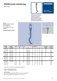
Cabezal con terminación roscada<br />
Cabezal Bulón Terminación roscada Contra- Peso<br />
Mat. EN-GJS-400-18-LT 34CrNiMo6V S355J2G3 tuerca total<br />
M<br />
mm<br />
A<br />
mm<br />
B<br />
mm<br />
C<br />
mm<br />
D<br />
mm<br />
E<br />
mm<br />
F<br />
mm<br />
H<br />
mm<br />
dB mm<br />
G<br />
mm<br />
L<br />
mm<br />
Ver. DV* ±mm mm<br />
DVmax* SW<br />
mm mm<br />
dS mm<br />
lM mm kg<br />
16 42 15 32 15 30 26 77 14 41,0 219,5 11,5 19 22 17 <strong>10</strong> 13 0,77<br />
20 52 18 40 17 35 31 93 16 50,2 254,5 14,5 22,2 26 19 12 16 1,37<br />
24 58 23 48 23 46 39 115 22 59,8 318,5 17,5 26 30 22 14 19 2,28<br />
27 68 23 54 25 47 44 125 24 66,6 348,3 20,0 30 34 24 16 22 3,36<br />
30 77 28 60 29 52 51 138 28 74,8 380,5 21,5 34 39 30 18 24 4,63<br />
36 90 28 72 33 64 58 167 32 89,3 475,0 26,0 40 46 32 22 29 8,18<br />
42 <strong>10</strong>4 33 84 37 70 66 190 36 <strong>10</strong>3 560,5 30,5 48 55 43 26 34 13,0<br />
48 120 38 96 41 78 74 213 40 118 645,0 34,0 56 64 46 30 38 19,7<br />
52 136 43 <strong>10</strong>4 46 85 84 231 45 126 686,5 37,5 58 66 50 32 42 24,7<br />
56 148 43 112 51 95 91 254 50 138 748,0 41,0 62 71 50 34 45 32,0<br />
60 162 48 120 56 <strong>10</strong>6 <strong>10</strong>0 275 55 146 790,5 42,5 66 75 55 36 48 39,2<br />
Excepto posibles modificaciones * Tras el prensado<br />
IM H<br />
E F<br />
SW<br />
G<br />
C<br />
B<br />
dB<br />
dM<br />
SW<br />
L ±<br />
ØDvmax<br />
SFb<br />
M<br />
Certificado: Z-14.7-413<br />
Módulo elástico: 150 ± <strong>10</strong> kN/mm 2<br />
Tolerancia d s:+ 5%<br />
Protección contra la corrosión:<br />
Galvanizado sin inyección interior<br />
Tolerancia<br />
L<br />
A<br />
D<br />
Øds<br />
9
<strong>10</strong><br />
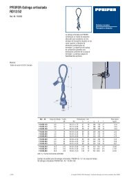
Detalles constructivos<br />
Las siguientes indicaciones para el sistema <strong>de</strong> atirantado <strong>PFEIFER</strong> tipo <strong>860</strong> facilitan el diseño <strong>de</strong> los puntos <strong>de</strong> conexión<br />
con la estructura e incluyen las disposiciones constructivas para la colocación y el correcto montaje <strong>de</strong>l sistema.<br />
Puntos <strong>de</strong> conexión<br />
En los puntos <strong>de</strong> conexión es necesario verificar la posición <strong>de</strong> los<br />
ejes <strong>de</strong> cada uno <strong>de</strong> los elementos constructivos a unir, ya que son<br />
las direcciones <strong>de</strong> transmisión <strong>de</strong> cargas. Dichos ejes <strong>de</strong>ben por<br />
tanto ser concurrentes en un punto. La fabricación <strong>de</strong> las placas <strong>de</strong><br />
anclaje <strong>de</strong>be realizarse respetando el diámetro <strong>de</strong>l taladro, la mínima<br />
distancia f mín <strong>de</strong>s<strong>de</strong> el centro <strong>de</strong>l taladro al extremo <strong>de</strong> la placa,<br />
el ancho mínimo c mín según la tabla <strong>de</strong>l cabezal, un lado <strong>de</strong> la placa<br />
paralelo a la base <strong>de</strong>l cabezal y la calidad a<strong>de</strong>cuada <strong>de</strong>l material<br />
(Fig. 1).<br />
Una estimación <strong>de</strong> las medidas <strong>de</strong> la placa pue<strong>de</strong> realizarse en función<br />
<strong>de</strong>l ángulo <strong>de</strong> la unión y <strong>de</strong>l diámetro <strong>de</strong>l taladro (Fig. 2).<br />
Disposiciones constructivas<br />
Durante la colocación <strong>de</strong>l sistema <strong>de</strong> atirantado es necesario evitar<br />
excentricida<strong>de</strong>s. La <strong>de</strong>sviación <strong>de</strong>l sistema con respecto a su eje<br />
teórico no <strong>de</strong>be superar 0,5º. En caso contrario se producirán tensiones<br />
no <strong>de</strong>seadas en los cabezales y placas <strong>de</strong> anclaje (Fig. 3).<br />
Especialmente en caso <strong>de</strong> montaje con cabezales girados uno respecto<br />
al otro, es necesario mantener una precisa alineación <strong>de</strong> los<br />
mismos (Figs. 4 y 5).<br />
Fig. 3 Desviación<br />
α ≤ 0,5°<br />
Fig. 1 Correcto Incorrecto<br />
Fig. 2<br />
Viga<br />
α<br />
Placa <strong>de</strong><br />
anclaje<br />
Fig. 4 Unión con cabezales girados<br />
r<br />
3,2*r<br />
3,2*r<br />
Viga<br />
4*r<br />
Fig. 5 Unión con cabezales en la misma dirección (recomendado)<br />
α<br />
Placa <strong>de</strong><br />
anclaje
Indicaciones adicionales<br />
Suministro y montaje<br />
Para facilitar el montaje, el sistema <strong>de</strong> atirantado <strong>PFEIFER</strong> se suministra<br />
premontado (Fig. 6).<br />
Para su colocación <strong>de</strong>be conseguirse el valor <strong>de</strong> la longitud <strong>de</strong>l sistema<br />
<strong>de</strong>seada mediante roscado <strong>de</strong> la barra ajustando <strong>de</strong> tal forma que<br />
el bulón pueda introducirse sin <strong>de</strong>sviaciones (Fig. 7). La introducción<br />
<strong>de</strong>l bulón a martillazos pue<strong>de</strong> dañar el cabezal y por tanto las garantías<br />
carecerían <strong>de</strong> vali<strong>de</strong>z.<br />
El sistema <strong>de</strong> atirantado se coloca con llaves <strong>de</strong> horquilla. También<br />
pue<strong>de</strong>n ser útiles con un correcto empleo las llaves ajustables o llave<br />
inglesa. En ejecuciones especiales y bajo pedido pue<strong>de</strong>n suministrarse<br />
llaves <strong>de</strong> horquilla. Las contratuercas <strong>de</strong>ben roscarse hasta el<br />
cabezal. Para la fijación <strong>de</strong> la contratuerca pue<strong>de</strong> utilizarse una llave<br />
<strong>de</strong> cintas para no dañar el acabado superficial (Fig. 8).<br />
En el ámbito <strong>de</strong>l control <strong>de</strong> calidad, es necesario verificar la profundidad<br />
<strong>de</strong> roscado en cada extremo <strong>de</strong> barra. El responsable <strong>de</strong>l montaje<br />
<strong>de</strong>be documentar y hacer constar en acta la comprobación realizada.<br />
La mínima profundidad <strong>de</strong> roscado queda garantizada al <strong>de</strong>saparecer<br />
totalmente la rosca <strong>de</strong> la barra en el interior <strong>de</strong> la contratuerca.<br />
Con longitu<strong>de</strong>s <strong>de</strong> roscado no estándar <strong>de</strong>ben adoptarse<br />
medidas especiales <strong>de</strong> control <strong>de</strong> la profundidad <strong>de</strong> roscado mínima.<br />
En caso <strong>de</strong> que el zincado superficial se <strong>de</strong>teriorase durante el montaje,<br />
<strong>de</strong>ben repararse las piezas <strong>de</strong> forma que que<strong>de</strong> asegurada una<br />
correcta protección contra la corrosión.<br />
Con longitu<strong>de</strong>s <strong>de</strong>l sistema superiores a los <strong>10</strong> m, el tirante <strong>de</strong>be izarse<br />
con al menos dos eslingas para evitar que se doble.<br />
Datos para solicitud <strong>de</strong> presupuestos y pedidos<br />
El diámetro <strong>de</strong>l elemento <strong>de</strong>be elegirse en función <strong>de</strong> la carga admisible<br />
(NR,d) indicada en las tablas correspondientes a las <strong>barras</strong> o a los<br />
cables. La carga admisible necesaria se <strong>de</strong>termina a través <strong>de</strong>l cálculo<br />
<strong>de</strong> la solicitación <strong>de</strong>l tirante.<br />
Al indicar la longitud <strong>de</strong>l sistema (Lsys) hay que consi<strong>de</strong>rar la mínima<br />
distancia <strong>de</strong>l tirante correspondiente, la longitud más corta <strong>de</strong>s<strong>de</strong> el<br />
punto <strong>de</strong> vista técnico y <strong>de</strong> suministro (Fig. 9).<br />
Los datos restantes, por ejemplo las longitu<strong>de</strong>s parciales L1 y L2,<br />
<strong>de</strong>ben indicarse en la casilla <strong>de</strong> Observaciones (Figs. <strong>10</strong> y 11).<br />
Fig. 6<br />
Fig. 7<br />
Fig.8<br />
Fig. 9<br />
Fig. <strong>10</strong><br />
Fig. 11<br />
L sys<br />
L2<br />
L1<br />
11
Datos <strong>de</strong>l cliente: Dirección <strong>de</strong> envío:<br />
Obra:<br />
Empresa: Empresa:<br />
Dirección: Dirección:<br />
Código postal / Ciudad: Código postal / Ciudad:<br />
Teléfono: Teléfono:<br />
Fax: Fax:<br />
Persona <strong>de</strong> contacto: Persona <strong>de</strong> contacto:<br />
Observaciones: Observaciones:<br />
1<br />
2<br />
3<br />
4<br />
5<br />
6<br />
7<br />
8<br />
9<br />
<strong>10</strong><br />
11<br />
12<br />
Solicitud <strong>de</strong> presupuesto<br />
Formulario <strong>de</strong> pedido<br />
<strong>Sistema</strong> <strong>de</strong> atirantado <strong>PFEIFER</strong><br />
Diámetro (mm)<br />
Máxima longitud <strong>de</strong>l sistema (mm)<br />
.<br />
Fax: 91 659 31 39<br />
<strong>PFEIFER</strong><br />
SEIL- UND HEBETECHNIK<br />
GMBH<br />
DR.-KARL-LENZ-STRASSE 66<br />
D-87700 MEMMINGEN<br />
TELEFON +49 (0)8331-937-393<br />
TELEFAX +49 (0)8331-937-350<br />
E-MAIL zugglie<strong>de</strong>r@pfeifer.<strong>de</strong><br />
INTERNET www.pfeifer.<strong>de</strong><br />
Pos. Observaciones Tratamiento Diámetro Longitud <strong>de</strong>l Cantidad<br />
Por ej. L1 superficial sistema<br />
zincado Sí / No mm mm<br />
Plazo <strong>de</strong> entrega:<br />
<strong>10</strong> y 12<br />
6.000<br />
16 hasta <strong>10</strong>0<br />
15.000<br />
Son válidas las condiciones generales <strong>de</strong> venta <strong>de</strong> <strong>PFEIFER</strong> Seil und Hebetechnik GMBH.<br />
Material <strong>de</strong>l cabezal: EN-GJS-400-18-LT (GGG40.3)<br />
Material <strong>de</strong> la barra: S460N<br />
Material <strong>de</strong>l disco: S355J2G3<br />
Todas las piezas están zincadas según DIN EN ISO 1.461 y DIN EN<br />
22.063. Las <strong>barras</strong> pue<strong>de</strong>n suministrarse sin tratar bajo pedido.
<strong>PFEIFER</strong><br />
SEIL- UND HEBETECHNIK<br />
GMBH<br />
J&P<br />
TECNICAS DE ANCLAJE S.L<br />
Holzer/KS<br />
2.8.1<br />
DR.-KARL-LENZ-STRASSE 66<br />
Avda. <strong>de</strong> los Pirineos, 25, nave 20<br />
San Sebastián <strong>de</strong> los Reyes<br />
D-87700 MEMMINGEN<br />
28700 MADRID<br />
BARCELONA<br />
TELEFON +49 (0)8331-937-393 TEL +34 (91) 659 31 85 TEL +34 (93) 475 <strong>10</strong> 83<br />
TELEFAX +49 (0)8331-937-350 FAX +34 (91) 659 31 39 FAX +34 (93) 475 <strong>10</strong> 84<br />
E-MAIL zugglie<strong>de</strong>r@pfeifer.<strong>de</strong> www.jp-anclajes.com<br />
INTERNET www.pfeifer.<strong>de</strong> jp@jp-anclajes.com