Lim itadores de Par Limitadores de Par LSC - setimetrasa
Lim itadores de Par Limitadores de Par LSC - setimetrasa
Lim itadores de Par Limitadores de Par LSC - setimetrasa

You also want an ePaper? Increase the reach of your titles
YUMPU automatically turns print PDFs into web optimized ePapers that Google loves.
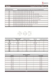
Chaveteros S/DIN 6885, Hoja 1<br />
2.1<br />
<strong>Lim</strong><strong>itadores</strong> <strong>de</strong> <strong>Par</strong> <strong>LSC</strong><br />
I<strong>de</strong>ntificación <strong>de</strong> Repuestos<br />
1: Camisa<br />
1T: Brida<br />
2: Núcleo<br />
3: Cono Móvil<br />
4: Tuerca Regulación<br />
5: Resortes Platillo<br />
6: Pieza <strong>de</strong> Arrastre<br />
7: Anillo <strong>de</strong> Fricción<br />
8: Resorte Retención<br />
9: Tornillo Cerraje<br />
10: Tuerca<br />
11: Grower<br />
12: Tornillo<br />
La sección representada encima<br />
<strong>de</strong>l eje, correspon<strong>de</strong> a la forma<br />
constructiva <strong>de</strong> los tamaños más<br />
pequeños.<br />
La sección representada <strong>de</strong>bajo<br />
<strong>de</strong> eje, correspon<strong>de</strong> a la forma<br />
constructiva <strong>de</strong> los tamaños más<br />
gran<strong>de</strong>s.<br />
Nuestras unida<strong>de</strong>s se suministran, normalmente, sin taladro y ranura; pero a indicación <strong>de</strong>l cliente, po<strong>de</strong>mos<br />
efectuar estos trabajos, cargando aparte el coste <strong>de</strong> las mismas.<br />
Este limitador es apto solo para trabajar en seco.<br />
Si el limitador ha <strong>de</strong> estar sometido a largos periodos <strong>de</strong> resbalamiento, consultar nuestro <strong>de</strong>partamento<br />
técnico.<br />
Tamaño<br />
C.V. a<br />
r.p.m.<br />
<strong>Par</strong><br />
mkg<br />
Velocida<br />
d<br />
Max.<br />
r.p.m.<br />
P.D.<br />
Total<br />
Max<br />
D1<br />
Diámetros Longitu<strong>de</strong>s<br />
Peso en<br />
Kg<br />
Mín<br />
D2 D3 D4 D5<br />
L1 L2 L3 L4<br />
<strong>LSC</strong>-12 0,017 12 4000 30 30 45 100 125 60 1 29 90<br />
<strong>LSC</strong>-24 0,033 24 3280 40 40 70 136 162 68 1 40 109<br />
<strong>LSC</strong>-36 0,050 36 2250 50 50 80 160 195 80 2 50 132<br />
<strong>LSC</strong>-60 0,086 60 2120 60 60 110 200 235 96 3 60 159<br />
<strong>LSC</strong>-96 0,134 96 1710 70 70 120 250 290 105 4 75 184<br />
<strong>LSC</strong>-192 0,268 192 1360 90 80 145 315 365 130 4 90 224<br />
<strong>LSC</strong>-300 0,418 300 1225 110 100 180 355 410 145 5 120 270<br />
Dimensiones sin compromiso Los pesos indicados, son con el taladro sin barrenar
<strong>Lim</strong>itador <strong>de</strong> <strong>Par</strong> para Ca<strong>de</strong>na Serie Ligera<br />
2.2<br />
<strong>Lim</strong><strong>itadores</strong> <strong>de</strong> <strong>Par</strong> para Ca<strong>de</strong>na<br />
1. Núcleo central <strong>de</strong>l mecanismo<br />
2. Disco <strong>de</strong> fricción (incorpora dos)<br />
3. Casquillo<br />
Tabla <strong>de</strong> Dimensiones (mm) <strong>de</strong> <strong>Lim</strong><strong>itadores</strong> <strong>de</strong> <strong>Par</strong> Serie Ligera<br />
Referencia<br />
LP-25-R1<br />
LP-25-R2<br />
LP-35-R1<br />
LP-35-R2<br />
LP-35-R8<br />
LP-50-R1<br />
LP-50-R2<br />
LP-50-R12<br />
LP-70-R1<br />
LP-70-R2<br />
LP-70-R12<br />
<strong>Par</strong> mKg Díam. Eje<br />
Min Max Bruto Max A<br />
0,2<br />
1<br />
2<br />
3<br />
4<br />
8<br />
10<br />
20<br />
3<br />
6<br />
8<br />
18<br />
25<br />
22<br />
45<br />
60<br />
60<br />
120<br />
145<br />
4. Plato <strong>de</strong> presión<br />
5. Resorte muelle <strong>de</strong> disco<br />
6. Aran<strong>de</strong>la guía <strong>de</strong>l resorte<br />
7. Aran<strong>de</strong>la <strong>de</strong> seguridad para la tuerca<br />
8. Tuerca almenada <strong>de</strong> ajuste <strong>de</strong> presión<br />
B C D<br />
E<br />
Max<br />
F<br />
Peso<br />
Aprox.<br />
kg<br />
Longitud<br />
Casquillo<br />
10 20 63 50 35 52 10 14 0,7 10-12-14<br />
15 25 90 65 40<br />
20 40 125 80 60<br />
25 65 175 110 95<br />
58<br />
78<br />
80<br />
108<br />
125<br />
160<br />
14 16 1,3 10-12-14-16<br />
20 20 2,7 12-14-16-20<br />
30 25 7,8<br />
14-16-20-22<br />
24-28-30<br />
El limitador <strong>de</strong> par o embrague <strong>de</strong> seguridad, es un elemento diseñado para absorver las sobrecargas<br />
producidas por bloqueos fortuitos en cualquier tipo <strong>de</strong> maquinaria. Su funcionamiento básico es el transmitir<br />
par mediante un elemento aprisionado entre dos discos <strong>de</strong> fricción cargados por un muelle <strong>de</strong> disco el cual<br />
es regulado por una tuerca.<br />
Cuando en la máquina se produce una carga superior a la que el limitador se halla regulado, se produce el<br />
<strong>de</strong>slizamiento <strong>de</strong>l elemento transmisor intercalado entre los discos <strong>de</strong> fricción sin <strong>de</strong>terioro <strong>de</strong> las partes<br />
débiles <strong>de</strong> la máquina; cuando esta sobrecarga cesa, se <strong>de</strong>tiene el <strong>de</strong>slizamiento y prosigue la transmisión<br />
<strong>de</strong> fuerza.
<strong>Lim</strong>itador <strong>de</strong> <strong>Par</strong> para Ca<strong>de</strong>na Serie Pesada<br />
Referencia<br />
<strong>Par</strong> máx.<br />
mKg<br />
2.3<br />
<strong>Lim</strong><strong>itadores</strong> <strong>de</strong> <strong>Par</strong> para Ca<strong>de</strong>na<br />
d máx. A B C D<br />
LP-100-R16 225 80 250 120 120 210<br />
LP-150-R16 340 90 300 180 130 260<br />
LP-200-R16 460 100 350 200 150 310
Referencia<br />
LPA-25-R1<br />
LPA-25-R2<br />
LPA-35-R1<br />
LPA-35-R2<br />
LPA-50-R1<br />
LPA-50-R2<br />
LPA-70-R1<br />
LPA-70-R2<br />
<strong>Par</strong> mkg<br />
Min. Max.<br />
0,2<br />
1<br />
2<br />
3<br />
4<br />
8<br />
10<br />
20<br />
3<br />
6<br />
8<br />
18<br />
22<br />
45<br />
60<br />
120<br />
A B C D E<br />
2.4<br />
Acoplamiento - <strong>Lim</strong>itador<br />
El acoplamiento - limitador <strong>de</strong> par reúne las ventajas<br />
<strong>de</strong> un acoplamiento normal por ca<strong>de</strong>na <strong>de</strong> rodillos y<br />
<strong>de</strong> un limitador <strong>de</strong> par o <strong>de</strong> esfuerzo, admitiendo una<br />
cierta <strong>de</strong>salineación entre ejes y controlando el par<br />
que se transmite <strong>de</strong> un eje al otro. El lugar i<strong>de</strong>al para<br />
su aplicación es el eje <strong>de</strong> salida <strong>de</strong> un reductor,<br />
uniendo la máquina conducida.<br />
Su facilidad <strong>de</strong> montaje, ya que se trata <strong>de</strong> un simple<br />
enganche <strong>de</strong> ca<strong>de</strong>na, permite separar ambos ejes en<br />
segundos.<br />
La utilización <strong>de</strong> este elemento <strong>de</strong> transmisión<br />
asegura totalmente la protección <strong>de</strong> toda la<br />
maquinaria conducida contra sobrecargas, bloqueos,<br />
etc.<br />
Fabricación standard y en stock permanente cuatro<br />
mo<strong>de</strong>los que van <strong>de</strong>s<strong>de</strong> 0,2 mKg hasta 120 mKg y<br />
una gama <strong>de</strong> diámetros <strong>de</strong> eje 15 mm hasta 110 mm.<br />
Díam.<br />
Eje Min.<br />
Díam<br />
Eje Max.<br />
Piñón <strong>Lim</strong>it. Piñón <strong>Lim</strong>it.<br />
80 102 73 30 50 15 10 40 20<br />
105 137 101 38 65 18 15 50 25<br />
125 187 145 50 80 20 20 80 40<br />
180 248 200 67 110 24 25 100 65
2.5<br />
<strong>Lim</strong>itador Electrónico <strong>de</strong> <strong>Par</strong> RIT-2<br />
Diagrama <strong>de</strong> Conexiones Dimensiones Generales<br />
Especificaciones Técnicas<br />
• Tensión <strong>de</strong> alimentación: 2 x 220 Vca. (Bajo pedido 110, 380 Vca.).<br />
• Frecuencia : 50 / 60 Hz.<br />
• Intensidad máxima: 5 A. sin transformador <strong>de</strong> intensidad (Cualquier alcance superior a través <strong>de</strong> un<br />
transformador /5).<br />
• Histéresis: Aprox. 0,5%.<br />
• Consumo: Menor que 2 VA.<br />
• Salida : Mediante relé con contacto conmutado libre <strong>de</strong> tensión con po<strong>de</strong>r <strong>de</strong> corte <strong>de</strong> 5 A o 1250 VA sobre<br />
carga resistiva.<br />
• Inmunidad a cortes <strong>de</strong> red: Inmune a cortes <strong>de</strong> tensión inferiores a 100 ms.<br />
• <strong>Lim</strong>ites <strong>de</strong> temperatura: En trabajo; -20º a +50 ºC.<br />
En almacén; -50º a +85 ºC.<br />
• Vida mecánica: Un millón <strong>de</strong> maniobras (con carga máxima).<br />
• Vida eléctrica: 500.000 operaciones (con carga máxima).<br />
• Aislamiento Entrada/Salida: Mayor <strong>de</strong> 2500 V.<br />
• Aislamiento entre contactos: 1000 V.<br />
• Sensibilidad: 20 mA.<br />
Funcionamiento<br />
• Conectar el circuito <strong>de</strong> intensidad en serie con las bornas 6 y 11 (max 5 A).<br />
• Conectar la tensión <strong>de</strong> alimentación entre las bornas 2 y 10 (220 V estándar).<br />
• Al efectuar el puente “Mando” entre las bornas 8 y 9 se encien<strong>de</strong> el led ver<strong>de</strong> y comienza la<br />
temporización “Tiempo Arranque” (0-45 seg.) durante la cual el RIT-2 queda inhibido.<br />
• Transcurrido el “Tiempo Arranque” si se supera la intensidad prefijada durante un tiempo ajustable (0 - 5<br />
seg.) “Tiempo Defecto” el relé <strong>de</strong> salida cambiará <strong>de</strong> estado y se encen<strong>de</strong>rá el led rojo.<br />
• Memorización <strong>de</strong>l Disparo: Si está hecho el puente 5 - 7 aunque <strong>de</strong>saparezca la sobrecarga el RIT-2<br />
permanecerá disparado.<br />
• Rearme: Local con el pulsador “Reset”<br />
Remoto, abriendo durante un tiempo mayor <strong>de</strong> 100 mseg. el puente 5 - 7<br />
• NOTA: En caso <strong>de</strong> trabajar con intensida<strong>de</strong>s superiores a 5 A. Debe utilizarse un transformador <strong>de</strong><br />
relación X/5