Boletin de Especificaciones 911-31S - S&C Electric Company
Boletin de Especificaciones 911-31S - S&C Electric Company
Boletin de Especificaciones 911-31S - S&C Electric Company

Create successful ePaper yourself
Turn your PDF publications into a flip-book with our unique Google optimized e-Paper software.
Aisladores <strong>de</strong> Cypoxyr <strong>de</strong> S&C<br />
Distribución en Interiores y Exteriores (4.8 kV hasta 46 kV)<br />
Condiciones <strong>de</strong> Venta<br />
NORMALES: Aplican las condiciones <strong>de</strong> venta normales<br />
por parte <strong>de</strong>l ven<strong>de</strong>dor que se estipulan en la Hoja <strong>de</strong> Precios<br />
150.<br />
ESPECÍFICO DE ESTE PRODUCTO:<br />
INCLUSIONES: Los Aisladores <strong>de</strong> Cypoxy <strong>de</strong> S&C se fabrican<br />
utilizando un sistema <strong>de</strong> resina epóxica cicloalifática<br />
marca Cypoxy <strong>de</strong> S&C. El material <strong>de</strong> Cypoxy no crea<br />
canales <strong>de</strong> conducción superficial, se limpia solo y resiste<br />
las inclemencias <strong>de</strong>l tiempo. El color estándar <strong>de</strong> los Aisladores<br />
<strong>de</strong> Cypoxy <strong>de</strong> S&C es gris. No hay ningún otro color<br />
disponible.<br />
Los Aisladores <strong>de</strong> Cypoxy <strong>de</strong> S&C vienen equipados con<br />
insertos <strong>de</strong> aluminio incrustados, los cuales tienen roscas<br />
Diciembre 19, 2011 © S&C <strong>Electric</strong> <strong>Company</strong><br />
<strong>Especificaciones</strong><br />
para adaptarse a los pernos <strong>de</strong> acero galvanizado. Tal y<br />
como se advierte en las tablas correspondientes <strong>de</strong> las páginas<br />
2 a la 6, los juegos <strong>de</strong> insertos en los dos extremos<br />
<strong>de</strong> los Aisladores Soporte <strong>de</strong> S&C se ofrecen en una o dos<br />
configuraciones estándar: ya sea en línea o fuera <strong>de</strong> línea a<br />
90° en relación el uno <strong>de</strong>l otro.<br />
EXCLUSIONES: Los Aisladores <strong>de</strong> Cypoxy <strong>de</strong> S&C no incluyen<br />
tornillería <strong>de</strong> montaje.<br />
Para Hacer Pedidos<br />
1. Obtenga el número <strong>de</strong> catálogo <strong>de</strong>l Aislador <strong>de</strong> Cypoxy<br />
<strong>de</strong>seado utilizando las tablas <strong>de</strong> las páginas 2 a la 6.<br />
2. Obtenga la letra <strong>de</strong>l sufijo <strong>de</strong> los adaptadores <strong>de</strong> espacio,<br />
en caso <strong>de</strong> que <strong>de</strong>see obtenerlos, utilizando la tabla <strong>de</strong> la<br />
página 7.<br />
Boletín <strong>de</strong> <strong>Especificaciones</strong> <strong>911</strong>-<strong>31S</strong>
Aisladores <strong>de</strong> Cypoxy <strong>de</strong> S&C<br />
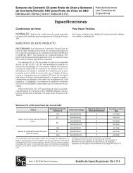
AISLADORES TIPO ESTACIÓN PARA EXTERIORES1<br />
Tipo<br />
De<br />
Soporte<br />
Configuración <strong>de</strong>l<br />
Inserto<br />
En Línea<br />
4 insertos en cada<br />
extremo, espaciado<br />
entre pernos <strong>de</strong> 3<br />
pulgadas (76 mm);<br />
barrenos con cuerda<br />
<strong>de</strong> ½ <strong>de</strong> pulgada—<br />
13 X ¾ <strong>de</strong> pulgada<br />
Capacidad, kV<br />
Nom. NBAI<br />
14.4 110<br />
25/34.5•<br />
150<br />
34.5 200<br />
46 250<br />
2 Boletín <strong>de</strong> <strong>Especificaciones</strong> <strong>de</strong> S&C <strong>911</strong>-<strong>31S</strong><br />
Altura, en<br />
Pulgadas<br />
(mm)<br />
10<br />
(254)<br />
14<br />
(356)<br />
18<br />
(457)<br />
22<br />
(559)<br />
1 Los aisladores <strong>de</strong> Cypoxy tipo estación <strong>de</strong> S&C cumplen o superan<br />
los requerimientos <strong>de</strong> resistencia mecánica y eléctrica establecidos<br />
por la Norma ANSI C29.9 (1983) con respecto a los aisladores <strong>de</strong><br />
porcelana <strong>de</strong> alta resistencia tipo estación.<br />
2 Calculado con tensión nominal.<br />
3 Para po<strong>de</strong>r alcanzar su nivel <strong>de</strong> resistencia <strong>de</strong> empotramiento<br />
nominal, los Aisladores <strong>de</strong> Cypoxy <strong>de</strong>ben estar montados sobre una<br />
superficie plana que sea por lo menos tan ancha como el diámetro<br />
Distancia<br />
<strong>de</strong> Fuga, en<br />
Pulgadas<br />
(mm)<br />
16 7 /8<br />
(429)<br />
26 1 /4<br />
(667)<br />
37 3 /8<br />
(949)<br />
57 3 /8<br />
(1457)<br />
Línea <strong>de</strong><br />
Fuga,<br />
mm/kV2<br />
Resistencia<br />
<strong>de</strong><br />
empotramiento,<br />
en<br />
Libras34<br />
Número<br />
<strong>de</strong><br />
Catálogo<br />
Página <strong>de</strong><br />
Referencia<br />
con<br />
Información<br />
Dimensional<br />
29.8 2000 PA-7252R1 8<br />
26.7 2000 PA-7253R1 8<br />
27.5 2000 PA-7254R1 8<br />
31.7 2000 PA-7255 8<br />
<strong>de</strong> la base <strong>de</strong>l aislador. A<strong>de</strong>más, la superficie <strong>de</strong> montaje <strong>de</strong>be estar<br />
libre <strong>de</strong> protuberancias, tales como grumos <strong>de</strong> material galvanizado,<br />
para evitar que el aislador se rompa cuando se aprieten los tornillos.<br />
4 Estos aisladores tienen diámetros raíz con cuerda. Para que<br />
puedan alcanzar su nivel <strong>de</strong> resistencia <strong>de</strong> empotramiento nominal,<br />
el extremo con el diámetro raíz más amplio (marcado como “Base”)<br />
<strong>de</strong>be estar dirigido hacia la superficie <strong>de</strong> montaje.<br />
• Aplica a los 34.5 kV cuando la distancia <strong>de</strong> fuga a tierra cumpla con<br />
los requisitos <strong>de</strong>l usuario.
AISLADORES PARA INTERIORES-EXTERIORES1<br />
Tipo Configuración <strong>de</strong>l Inserto<br />
De<br />
Soporte<br />
Especiali-<br />
zado<br />
Fuera <strong>de</strong> Línea a 90º<br />
2 insertos en cada<br />
extremo, espaciado entre<br />
pernos <strong>de</strong> 2¼ pulgadas<br />
(57 mm); barrenos con<br />
cuerda <strong>de</strong> 1 /8 <strong>de</strong> pulgada<br />
—16 X 5 /8 <strong>de</strong> pulgada<br />
En Línea<br />
4 insertos en cada<br />
extremo, espaciado entre<br />
pernos <strong>de</strong> 3 pulgadas (76<br />
mm); barrenos con cuerda<br />
<strong>de</strong> ½ <strong>de</strong> pulgada—13 X ¾<br />
<strong>de</strong> pulgada<br />
En Línea<br />
1 inserto en cada extremo,<br />
centrado; un barreno<br />
con cuerda <strong>de</strong> ½ <strong>de</strong><br />
pulgada—13 X 3 /8 <strong>de</strong> pulgada<br />
Capacidad,<br />
kV Altura, en<br />
Pulgadas<br />
Nom. NBAI (mm)<br />
14.4 110<br />
25<br />
150<br />
34.5 200<br />
l 45<br />
6 3 /4<br />
(171)<br />
10<br />
(254)<br />
14<br />
(356)<br />
2 3 /4<br />
(70)<br />
1 Calculado con tensión nominal.<br />
2 Para po<strong>de</strong>r alcanzar su nivel <strong>de</strong> resistencia <strong>de</strong> empotramiento<br />
nominal, los Aisladores <strong>de</strong> Cypoxy <strong>de</strong>ben estar montados sobre una<br />
superficie plana que sea por lo menos tan ancha como el diámetro <strong>de</strong><br />
la base <strong>de</strong>l aislador. A<strong>de</strong>más, la superficie <strong>de</strong> montaje <strong>de</strong>be estar libre<br />
<strong>de</strong> protuberancias, tales como grumos <strong>de</strong> material galvanizado, para<br />
evitar que el aislador se rompa cuando se aprieten los tornillos.<br />
l Este aislador sirve como espaciador <strong>de</strong> navajas en las Cuchillas <strong>de</strong><br />
Puenteo para Regulador—Tipo XL. Cuando se utiliza por sí solo, su<br />
Distancia<br />
<strong>de</strong><br />
Fuga, en<br />
Pulgadas<br />
(mm)<br />
14 1 /8<br />
(359)<br />
24 1 /8<br />
(613)<br />
26 1 /4<br />
(667)<br />
2 3 /4<br />
(70)<br />
Línea<br />
<strong>de</strong><br />
Fuga,<br />
mm/<br />
kV1<br />
24.9<br />
Aisladores <strong>de</strong> Cypoxy <strong>de</strong> S&C<br />
Resistencia<br />
<strong>de</strong> empotramiento,<br />
en Libras2<br />
Número <strong>de</strong><br />
Catálogo<br />
Página <strong>de</strong><br />
Referencia<br />
con<br />
Información<br />
Dimensional<br />
1200 PA-7191d 9<br />
24.5 1000 PA-7192d 9<br />
19.3 2000 PA-7253R1dfa 9<br />
116.7<br />
600 PA-7188<br />
capacidad nominal es <strong>de</strong> 600 voltios.<br />
d Este aislador tiene diámetros raíz con cuerda. Para que pueda<br />
alcanzar su nivel <strong>de</strong> resistencia <strong>de</strong> empotramiento nominal, el extremo<br />
con el diámetro raíz más amplio (marcado como “Base”) <strong>de</strong>be estar<br />
dirigido hacia la superficie <strong>de</strong> montaje.<br />
f Sólo para uso en interiores cuando se utilice a 34.5 kV.<br />
a Sustituye al Número <strong>de</strong> Catálogo PA-7193. Cuando reemplace un<br />
Aislador con Número <strong>de</strong> Catálogo PA-7193, especifique un Adaptador<br />
<strong>de</strong> Espaciador con Número <strong>de</strong> Catálogo S-86542.<br />
Boletín <strong>de</strong> <strong>Especificaciones</strong> <strong>de</strong> S&C <strong>911</strong>-<strong>31S</strong> 3<br />
9
Aisladores <strong>de</strong> Cypoxy <strong>de</strong> S&C<br />
AISLADORES PARA INTERIORES<br />
Tipo Configuración <strong>de</strong>l Inserto<br />
Barra<br />
De<br />
Soporte<br />
En Línea<br />
1 inserto en cada extremo,<br />
centrado; un barreno<br />
con cuerda <strong>de</strong> ½ <strong>de</strong> pul-<br />
gada—13 X 3 /8 <strong>de</strong> pulgada<br />
Fuera <strong>de</strong> Línea a 90º<br />
2 insertos en cada<br />
extremo, espaciado entre<br />
pernos <strong>de</strong> 3 pulgadas (76<br />
mm); barrenos con cuerda<br />
<strong>de</strong> ½ <strong>de</strong> pulgada—13 X ¾<br />
<strong>de</strong> pulgada<br />
En Línea<br />
2 insertos en cada<br />
extremo, espaciado entre<br />
pernos <strong>de</strong> 2 pulgadas<br />
(51 mm) y 2 insertos en<br />
cada extremo, espa-<br />
ciado entre pernos <strong>de</strong> 1 3 /8<br />
(35 mm); h barrenos con<br />
cuerda <strong>de</strong> 3 /8 <strong>de</strong> pulgada<br />
—16 X 5 /8 <strong>de</strong> pulgada<br />
Capacidad,<br />
kV Altura, en<br />
Pulgadas<br />
Nom. NBAI<br />
(mm)<br />
4.8 60 3 1 /2<br />
(89)<br />
13.8 95 6<br />
(152)<br />
4.8 60 5<br />
(127)<br />
13.8 95 7 1 /2<br />
(191)<br />
13.8 95 6 1 /4<br />
(159)<br />
25 125 7 1 /2<br />
(191)<br />
25 150 10<br />
(254)<br />
1 Calculado con tensión nominal.<br />
2 Para po<strong>de</strong>r alcanzar su nivel <strong>de</strong> resistencia <strong>de</strong> empotramiento<br />
nominal, los Aisladores <strong>de</strong> Cypoxy <strong>de</strong>ben estar montados sobre una<br />
superficie plana que sea por lo menos tan ancha como el diámetro <strong>de</strong><br />
la base <strong>de</strong>l aislador. A<strong>de</strong>más, la superficie <strong>de</strong> montaje <strong>de</strong>be estar libre<br />
<strong>de</strong> protuberancias, tales como grumos <strong>de</strong> material galvanizado, para<br />
evitar que el aislador se rompa cuando se aprieten los tornillos.<br />
4 Boletín <strong>de</strong> <strong>Especificaciones</strong> <strong>de</strong> S&C <strong>911</strong>-<strong>31S</strong><br />
Distancia<br />
<strong>de</strong><br />
Fuga, en<br />
Pulgadas<br />
(mm)<br />
4 7 /8<br />
(124)<br />
12 1 /8<br />
(308)<br />
7 3 /4<br />
(197)<br />
13<br />
(330)<br />
12 1 /4<br />
(311)<br />
18 1 /2<br />
(470)<br />
26 1 /8<br />
(664)<br />
Línea<br />
<strong>de</strong><br />
Fuga,<br />
mm/<br />
kV1<br />
Resistencia<br />
<strong>de</strong> empotramiento,<br />
en Libras2<br />
Número <strong>de</strong><br />
Catálogo<br />
Página <strong>de</strong><br />
Referencia<br />
con<br />
Información<br />
Dimensional<br />
25.8 1000 PA-7164d 10<br />
22.3 1250 PA-7163d 10<br />
41.0 1250 PA-7166 10<br />
23.9 1250 PA-7162d 10<br />
22.5 1250 PA-7181 10<br />
18.8 1000 PA-7183 10<br />
26.6 1000 PA-7205 h 10<br />
h El PA-7205 tiene 4 insertos en cada extreme con un espaciado<br />
entre pernos <strong>de</strong> 2 pulgadas.<br />
d Este aislador tiene diámetros raíz con cuerda. Para que pueda<br />
alcanzar su nivel <strong>de</strong> resistencia <strong>de</strong> empotramiento nominal, el extremo<br />
con el diámetro raíz más amplio (marcado como “Base”) <strong>de</strong>be estar<br />
dirigido hacia la superficie <strong>de</strong> montaje.<br />
LA TABLA CONTINÚA v
AISLADORES PARA INTERIORES—Continuación<br />
Tipo Configuración <strong>de</strong>l Inserto<br />
De<br />
Soporte<br />
En Línea<br />
2 insertos, espaciado<br />
entre pernos <strong>de</strong> 2 pulgadas<br />
(51 mm); barrenos con<br />
cuerda <strong>de</strong> 3 /8 <strong>de</strong> pulgada<br />
—16 X 5 /8 <strong>de</strong> pulgada<br />
1 inserto, centrado,<br />
barreno con cuerda <strong>de</strong><br />
5 /8 <strong>de</strong> pulgada—11 X 7 /8 <strong>de</strong><br />
pulgada<br />
4 insertos, espaciado<br />
entre pernos <strong>de</strong> 2 pulgadas<br />
(51 mm); barrenos con<br />
cuerda <strong>de</strong> 3 /8 <strong>de</strong> pulgada<br />
—16 X 5 /8 <strong>de</strong> pulgada<br />
En Línea<br />
2 insertos, espaciado<br />
entre pernos <strong>de</strong> 2 pulgadas<br />
(51 mm); barrenos con<br />
cuerda <strong>de</strong> 3 /8 <strong>de</strong> pulgada<br />
—16 X 5 /8 <strong>de</strong> pulgada<br />
1 inserto, centrado,<br />
barreno con cuerda <strong>de</strong><br />
5 /8 <strong>de</strong> pulgada—11 X 7 /8 <strong>de</strong><br />
pulgada<br />
2 insertos, espaciado<br />
entre pernos <strong>de</strong> 2 pulgadas<br />
(51 mm); barrenos con<br />
cuerda <strong>de</strong> 3 /8 <strong>de</strong> pulgada<br />
—16 X 5 /8 <strong>de</strong> pulgada<br />
Capacidad,<br />
kV Altura, en<br />
Pulgadas<br />
Nom. NBAI<br />
(mm)<br />
5 60<br />
15 95<br />
25 125<br />
5 60<br />
15 95<br />
25 125<br />
3 1 /2<br />
(89)<br />
6<br />
(152)<br />
7 1 /2<br />
(191)<br />
8 1 /2<br />
(216)<br />
3 1 /2<br />
(89)<br />
6<br />
(152)<br />
7 1 /2<br />
(191)<br />
8 1 /2<br />
(216)<br />
1 Calculado con tensión nominal.<br />
2 Para po<strong>de</strong>r alcanzar su nivel <strong>de</strong> resistencia <strong>de</strong> empotramiento<br />
nominal, los Aisladores <strong>de</strong> Cypoxy <strong>de</strong>ben estar montados sobre una<br />
superficie plana que sea por lo menos tan ancha como el diámetro <strong>de</strong><br />
la base <strong>de</strong>l aislador. A<strong>de</strong>más, la superficie <strong>de</strong> montaje <strong>de</strong>be estar libre<br />
<strong>de</strong> protuberancias, tales como grumos <strong>de</strong> material galvanizado, para<br />
evitar que el aislador se rompa cuando se aprieten los tornillos.<br />
Distancia<br />
<strong>de</strong><br />
Fuga, en<br />
Pulgadas<br />
(mm)<br />
Línea<br />
<strong>de</strong><br />
Fuga,<br />
mm/<br />
kV1<br />
Aisladores <strong>de</strong> Cypoxy <strong>de</strong> S&C<br />
Resistencia<br />
<strong>de</strong><br />
empotramiento,<br />
en<br />
Libras23<br />
Número <strong>de</strong><br />
Catálogo<br />
Página <strong>de</strong><br />
Referencia<br />
con<br />
Información<br />
Dimensional<br />
6<br />
(152) 30.5 2000 PA-7310 11<br />
12 1 /4<br />
(311) 20.7 1250 PA-7280 11<br />
18 1 /2<br />
(470) 18.8 1000 PA-7290 11<br />
22 1 /2<br />
(572) 22.9 1000 PA-7340 11<br />
6<br />
(152) 30.5 2000 PA-7311 11<br />
12 1 /4<br />
(311) 20.7 1250 PA-7281 11<br />
18 1 /2<br />
(470) 18.8 1000 PA-7291 11<br />
22 1 /2<br />
(572) 22.9 1000 PA-7341 11<br />
3 Estos aisladores tienen diámetros raíz con cuerda. Para que<br />
puedan alcanzar su nivel <strong>de</strong> resistencia <strong>de</strong> empotramiento nominal, el<br />
extremo con el diámetro raíz más amplio (marcado como “Base”) <strong>de</strong>be<br />
estar dirigido hacia la superficie <strong>de</strong> montaje.<br />
LA TABLA CONTINÚA v<br />
Boletín <strong>de</strong> <strong>Especificaciones</strong> <strong>de</strong> S&C <strong>911</strong>-<strong>31S</strong> 5
Aisladores <strong>de</strong> Cypoxy <strong>de</strong> S&C<br />
AISLADORES PARA INTERIORES—Continuación<br />
Tipo Configuración <strong>de</strong>l Inserto<br />
De<br />
Soporte<br />
En Línea<br />
2 insertos, espaciado<br />
entre pernos <strong>de</strong> 2 pulgadas<br />
(51 mm); barrenos con<br />
cuerda <strong>de</strong> 3 /8 <strong>de</strong> pulgada<br />
—16 X 5 /8 <strong>de</strong> pulgada<br />
4 insertos, espaciado<br />
entre pernos <strong>de</strong> 2 pulgadas<br />
(51 mm); barrenos con<br />
cuerda <strong>de</strong> 3 /8 <strong>de</strong> pulgada<br />
—16 X 5 /8 <strong>de</strong> pulgada<br />
En Línea<br />
4 insertos, espaciado<br />
entre pernos <strong>de</strong> 2 pulgadas<br />
(51 mm); barrenos con<br />
cuerda <strong>de</strong> 3 /8 <strong>de</strong> pulgada<br />
—16 X 5 /8 <strong>de</strong> pulgada<br />
4 insertos, espaciado<br />
entre pernos <strong>de</strong> 2 pulgadas<br />
(51 mm); barrenos con<br />
cuerda <strong>de</strong> 3 /8 <strong>de</strong> pulgada<br />
—16 X 5 /8 <strong>de</strong> pulgada<br />
Capacidad,<br />
kV Altura, en<br />
Pulgadas<br />
Nom. NBAI<br />
(mm)<br />
5 60<br />
15 95<br />
25 125<br />
5 60<br />
15 95<br />
25 125<br />
6 Boletín <strong>de</strong> <strong>Especificaciones</strong> <strong>de</strong> S&C <strong>911</strong>-<strong>31S</strong><br />
3 1 /2<br />
(89)<br />
6<br />
(152)<br />
7 1 /2<br />
(191)<br />
8 1 /2<br />
(216)<br />
3 1 /2<br />
(89)<br />
6<br />
(152)<br />
7 1 /2<br />
(191)<br />
8 1 /2<br />
(216)<br />
1 Calculado con tensión nominal.<br />
2 Para po<strong>de</strong>r alcanzar su nivel <strong>de</strong> resistencia <strong>de</strong> empotramiento<br />
nominal, los Aisladores <strong>de</strong> Cypoxy <strong>de</strong>ben estar montados sobre una<br />
superficie plana que sea por lo menos tan ancha como el diámetro <strong>de</strong><br />
la base <strong>de</strong>l aislador. A<strong>de</strong>más, la superficie <strong>de</strong> montaje <strong>de</strong>be estar libre<br />
<strong>de</strong> protuberancias, tales como grumos <strong>de</strong> material galvanizado, para<br />
evitar que el aislador se rompa cuando se aprieten los tornillos.<br />
Distancia<br />
<strong>de</strong><br />
Fuga, en<br />
Pulgadas<br />
(mm)<br />
Línea<br />
<strong>de</strong><br />
Fuga,<br />
mm/<br />
kV1<br />
Resistencia<br />
<strong>de</strong><br />
empotramiento,<br />
en<br />
Libras23<br />
Número <strong>de</strong><br />
Catálogo<br />
Página <strong>de</strong><br />
Referencia<br />
con<br />
Información<br />
Dimensional<br />
6<br />
(152) 30.5 2000 PA-7312 11<br />
12 1 /4<br />
(311) 20.7 1250 PA-7282 11<br />
18 1 /2<br />
(470)<br />
22 1 /2<br />
(572)<br />
18.8 1000 PA-7292 11<br />
22.9 1000 PA-7342 11<br />
6<br />
(152) 30.5 2000 PA-7313 11<br />
12 1 /4<br />
(311) 20.7 1250 PA-7283 11<br />
18 1 /2<br />
(470) 18.8 1000 PA-7293 11<br />
22 1 /2<br />
(572) 22.9 1000 PA-7343 11<br />
3 Estos aisladores tienen diámetros raíz con cuerda. Para que<br />
puedan alcanzar su nivel <strong>de</strong> resistencia <strong>de</strong> empotramiento nominal, el<br />
extremo con el diámetro raíz más amplio (marcado como “Base”) <strong>de</strong>be<br />
estar dirigido hacia la superficie <strong>de</strong> montaje.
ADAPTADORES DE ESPACIADORES<br />
Ilustración Descripción<br />
Acero estampado galvanizado—para utilizarse<br />
en la adaptación <strong>de</strong>l espaciado entre pernos<br />
<strong>de</strong> 3 pulgadas (76 mm) <strong>de</strong>l aislador (para los<br />
pernos <strong>de</strong> ½ <strong>de</strong> pulgada—13) al espaciado entre<br />
pernos <strong>de</strong> 2¼ pulgadas (57 mm) (los barrenos<br />
con espaciado entre pernos <strong>de</strong> 2¼ pulgadas<br />
[57 mm] tienen cuerda para los pernos <strong>de</strong> 3 /8 <strong>de</strong><br />
pulgada—16)<br />
Acero estampado galvanizado—para utilizarse<br />
en la adaptación <strong>de</strong>l espaciado entre pernos <strong>de</strong><br />
2¼ pulgadas (57 mm) <strong>de</strong>l aislador (para los pernos<br />
<strong>de</strong> 3 /8 <strong>de</strong> pulgada—16) al espaciado entre pernos<br />
<strong>de</strong> 3 pulgadas (76 mm) (para los pernos <strong>de</strong> ½ <strong>de</strong><br />
pulgada—13)<br />
Acero estampado galvanizado—para utilizarse<br />
en la adaptación <strong>de</strong>l espaciado entre pernos <strong>de</strong><br />
2 pulgadas (51 mm) <strong>de</strong>l aislador (para los pernos<br />
<strong>de</strong> 3 /8 <strong>de</strong> pulgada—16) al espaciado entre pernos<br />
3 pulgadas (76 mm) (para los pernos <strong>de</strong> ½ <strong>de</strong><br />
pulgada—13)<br />
Acero estampado galvanizado—para utilizarse<br />
en la adaptación <strong>de</strong>l espaciado entre pernos <strong>de</strong><br />
<strong>de</strong> 1 3 /8 pulgadas (35 mm) <strong>de</strong>l aislador (para los<br />
pernos <strong>de</strong> 3 /8 <strong>de</strong> pulgada—16) al espaciado entre<br />
pernos <strong>de</strong> 3 pulgadas (76 mm) (para los pernos <strong>de</strong><br />
½ <strong>de</strong> pulgada—13)<br />
Aleación <strong>de</strong> aluminio fundido— para utilizarse en<br />
la adaptación <strong>de</strong>l espaciado entre pernos <strong>de</strong> <strong>de</strong><br />
1 3 /8 pulgadas (35 mm) <strong>de</strong>l aislador y en el espaciado<br />
entre pernos <strong>de</strong> 2 pulgadas (51 mm) <strong>de</strong>l<br />
aislador (para los pernos <strong>de</strong> 3 /8 <strong>de</strong> pulgada—16)<br />
al espaciado entre pernos <strong>de</strong> 3 pulgadas (76 mm)<br />
(los barrenos con espaciado entre pernos <strong>de</strong> 3<br />
pulgadas [76 mm] tienen cuerda para los pernos<br />
<strong>de</strong> ½ <strong>de</strong> pulgada—13)<br />
Altura, en<br />
Pulgadas<br />
(mm)<br />
15 /16<br />
(24)<br />
15 /16<br />
(24)<br />
15 /16<br />
(24)<br />
15 /16<br />
(24)<br />
3 /4<br />
(19)<br />
Aisladores <strong>de</strong> Cypoxy <strong>de</strong> S&C<br />
Para Utilizarse<br />
en el Aislador<br />
con Número <strong>de</strong><br />
Catálogo<br />
PA-7166<br />
PA-7162<br />
PA-7193<br />
PA-7191<br />
PA-7192<br />
PA-7181<br />
PA-7183<br />
PA-7181<br />
PA-7183<br />
PA-7181<br />
PA-7183<br />
Número <strong>de</strong><br />
Catálogo<br />
S-82274-1<br />
S-82274-2<br />
S-82274-3<br />
S-82274-4<br />
S-86016<br />
Boletín <strong>de</strong> <strong>Especificaciones</strong> <strong>de</strong> S&C <strong>911</strong>-<strong>31S</strong> 7
Aisladores <strong>de</strong> Cypoxy <strong>de</strong> S&C<br />
AISLADORES TIPO ESTACIÓN PARA EXTERIORES<br />
Tipo<br />
De<br />
Soporte<br />
Nom. NBAI<br />
14.4<br />
25<br />
34.5<br />
46<br />
110<br />
150<br />
200<br />
250<br />
Capacidad<br />
Resistencia<br />
<strong>de</strong><br />
Baja<br />
Frecuencia,<br />
Seca<br />
por 1 Min.<br />
70<br />
95<br />
95<br />
120<br />
NÚMEROS DE CATÁLOGO<br />
PA-7252R1, PA-7253R1, Y PA-7254R1<br />
Resisten<br />
cia <strong>de</strong><br />
Baja<br />
Frecuencia,Hú-<br />
meda<br />
por<br />
10 Seg.<br />
60<br />
80<br />
80<br />
100<br />
Distancia <strong>de</strong><br />
Fuga, en<br />
Pulgadas<br />
(mm)<br />
16 7 /8 (429)<br />
26 1 /4 (667)<br />
37 3 /8 (949)<br />
57 3 /8 (1457)<br />
Distancia<br />
<strong>de</strong> Arqueo<br />
en<br />
Seco, en<br />
Pulgadas<br />
(mm)<br />
10 (254)<br />
14 (356)<br />
18 (457)<br />
22 (559)<br />
1 Para que puedan alcanzar su nivel <strong>de</strong> resistencia <strong>de</strong> empotramiento<br />
nominal, los aisladores <strong>de</strong> Cypoxy <strong>de</strong>ben estar montados sobre una<br />
superficie plana que sea por lo menos tan ancha como el diámetro <strong>de</strong><br />
la base <strong>de</strong>l aislador.<br />
8 Boletín <strong>de</strong> <strong>Especificaciones</strong> <strong>de</strong> S&C <strong>911</strong>-<strong>31S</strong><br />
AISLADOR DE CYPOXY<br />
Capacidad <strong>de</strong> la Resistencia<br />
Mecánica, en Libras<br />
EmpotraCompre-<br />
Tracción<br />
miento12sión 2000<br />
2000<br />
2000<br />
2000<br />
Dimensiones en pulgadas (mm)<br />
10 000<br />
10 000<br />
12 000<br />
14 000<br />
20 000<br />
20 000<br />
20 000<br />
20 000<br />
INSERTO DE ALUMINIO<br />
INCRUSTADO (CON CUERDA<br />
SOBREDIMENSIONADA<br />
PARA LA TORNILLERÍA DE<br />
ACERO GALVANIZADO DE ½<br />
PULGADA—13)<br />
Número <strong>de</strong><br />
Catálogo<br />
PA-7252R1<br />
PA-7253R1<br />
PA-7254R1<br />
PA-7255<br />
DETALLE DEL INSERTO<br />
Número T.R.<br />
(para el<br />
aislador tipo<br />
estación <strong>de</strong><br />
porcelana<br />
correspondiente)<br />
205<br />
208<br />
210<br />
214<br />
Dimensiones en<br />
Pulgadas (mm)<br />
H D 1<br />
10 (254)<br />
14 (356)<br />
18 (457)<br />
22 (559)<br />
5 (127)<br />
5 1 /4 (133)<br />
6 (152)<br />
6 1 /2 (165)<br />
Peso<br />
Neto, en<br />
Libras<br />
(Kg.)<br />
10 (4.5)<br />
15 (6.8)<br />
21 (9.5)<br />
32 (14.4)<br />
2 Estos aisladores tienen diámetros raíz con cuerda. Para que puedan<br />
alcanzar su nivel <strong>de</strong> resistencia <strong>de</strong> empotramiento nominal, el extremo<br />
con el diámetro raíz más amplio (marcado como “Base”) <strong>de</strong>be estar<br />
dirigido hacia la superficie <strong>de</strong> montaje.
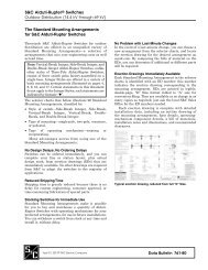
AISLADORES TIPO ESTACIÓN PARA EXTERIORES<br />
INSERTO DE ALUMINIO<br />
INCRUSTADO<br />
AISLADOR DE<br />
CYPOXY<br />
Tipo<br />
De<br />
Soporte<br />
Especializado<br />
NÚMEROS DE CATÁLOGO<br />
PA-7191 Y PA-7192<br />
DETALLE DEL INSERTO<br />
(PA-7191, PA-7192, Y PA-7188)<br />
Nom. NBAI<br />
14.4<br />
25<br />
34.5<br />
110<br />
150<br />
200<br />
Capacidad<br />
Resistencia<br />
<strong>de</strong><br />
Baja<br />
Frecuencia,<br />
Seca<br />
por 1 Min.<br />
50<br />
70<br />
95<br />
Resistencia<br />
<strong>de</strong><br />
Baja<br />
Frecuencia,Húmeda<br />
por<br />
10 Seg.<br />
45<br />
60<br />
80<br />
Distancia<br />
<strong>de</strong><br />
Fuga, en<br />
Pulgadas<br />
(mm)<br />
14 1 /8<br />
(359)<br />
24 1 /8<br />
(613)<br />
26 1 /4<br />
(667)<br />
l 45 15 - 2 3 /4<br />
(70)<br />
Distancia<br />
<strong>de</strong><br />
Arqueo<br />
en<br />
Seco, en<br />
Pulgadas<br />
(mm)<br />
6 3 /4<br />
(171)<br />
10<br />
(254)<br />
14<br />
(356)<br />
2 1 /4<br />
(57)<br />
NÚMEROS DE CATÁLOGO<br />
PA-7253R1<br />
Capacidad <strong>de</strong> la Resistencia<br />
Mecánica, en Libras<br />
Empotramiento1<br />
Tracción<br />
1200<br />
1000<br />
2000<br />
1 Para que puedan alcanzar su nivel <strong>de</strong> resistencia <strong>de</strong> empotramiento<br />
nominal, los aisladores <strong>de</strong> Cypoxy <strong>de</strong>ben estar montados sobre una<br />
superficie plana que sea por lo menos tan ancha como el diámetro <strong>de</strong><br />
la base <strong>de</strong>l aislador.<br />
l Este aislador sirve como espaciador <strong>de</strong> cuchilla en los Interruptores<br />
<strong>de</strong> Puenteo para Regulador <strong>de</strong> S&C—Tipo XL. Cuando se utiliza por sí<br />
solo su capacidad nominal es <strong>de</strong> 600 voltios.<br />
600<br />
Dimensiones en pulgadas (mm)<br />
5 000<br />
5 000<br />
10 000<br />
Aisladores <strong>de</strong> Cypoxy <strong>de</strong> S&C<br />
INSERTO DE ALUMINIO<br />
INCRUSTADO<br />
AISLADOR DE<br />
CYPOXY<br />
DETALLE DEL INSERTO<br />
(PA-7253R1)<br />
Dimensiones en<br />
Pulgadas (mm)<br />
Número <strong>de</strong><br />
Compre- Catálogo<br />
sión H R S<br />
20 000<br />
20 000<br />
20 000<br />
PA-7191d<br />
PA-7192d<br />
PA-7253R1df<br />
6 3 /4<br />
(171)<br />
10<br />
(254)<br />
14<br />
(356)<br />
3 000 20 000 PA-7188 2 3 /4<br />
(70)<br />
Número <strong>de</strong> Catálogo<br />
PA-7188<br />
1 /4<br />
(6)<br />
1 /4<br />
(6)<br />
-<br />
5 /8<br />
(16)<br />
5 /8<br />
(16)<br />
3 /4<br />
(19)<br />
Tamaño <strong>de</strong><br />
la Rosca<br />
<strong>de</strong>l Inserto<br />
3 /8 ”-16h<br />
3 /8 ”-16h<br />
1 /2 ”-13h<br />
Peso<br />
Neto, en<br />
Libras<br />
(Kg.)<br />
4 1 /2<br />
(2.0)<br />
7<br />
(3.2)<br />
15<br />
(6.8)<br />
Boletín <strong>de</strong> <strong>Especificaciones</strong> <strong>de</strong> S&C <strong>911</strong>-<strong>31S</strong> 9<br />
-<br />
3 /4<br />
(19)<br />
1 /2 ”-13<br />
1<br />
(0.5)<br />
d Este aislador tiene diámetros raíz con cuerda. Para que pueda<br />
alcanzar su resistencia <strong>de</strong> empotramiento nominal, el extremo que<br />
tenga el diámetro raíz más amplio (marcado como “Base”) <strong>de</strong>be estar<br />
dirigido hacia la superficie <strong>de</strong> montaje.<br />
f Para uso exclusivo en interiores cuando se aplique a 34.5 kV.<br />
h Cuerda sobredimensionada para la tornillería <strong>de</strong> acero galvanizado.
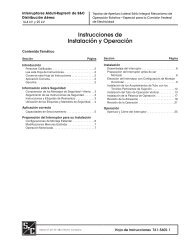
Aisladores <strong>de</strong> Cypoxy <strong>de</strong> S&C<br />
AISLADORES PARA INTERIORES<br />
NÚMEROS DE CATÁLOGO<br />
PA-7164 Y PA-7163<br />
Tipo<br />
Barra<br />
De<br />
Soporte<br />
Nom. NBAI<br />
4.8<br />
13.8<br />
4.8<br />
13.8<br />
13.8<br />
25<br />
25<br />
60<br />
95<br />
60<br />
95<br />
95<br />
125<br />
150<br />
Capacidad<br />
Resistencia<br />
<strong>de</strong><br />
Baja<br />
Frecuencia,<br />
Seca<br />
por 1<br />
Min.<br />
19<br />
36<br />
19<br />
36<br />
36<br />
60<br />
60<br />
Resistenca<br />
NÚMEROS DE CATÁLOGO<br />
PA-7166 Y PA-7162<br />
INSERTO DE ALUMINIO<br />
INCRUSTADO<br />
AISLADOR DE<br />
CYPOXY<br />
Distancia<br />
<strong>de</strong><br />
Fuga, en<br />
Pulgadas<br />
(mm)<br />
Distancia<br />
<strong>de</strong><br />
Arqueo<br />
en<br />
Seco, en<br />
Pulgadas<br />
(mm)<br />
10 Boletín <strong>de</strong> <strong>Especificaciones</strong> <strong>de</strong> S&C <strong>911</strong>-<strong>31S</strong><br />
15<br />
26<br />
15<br />
26<br />
26<br />
40<br />
40<br />
4 7 /8<br />
(124)<br />
12 1 /8<br />
(308)<br />
7 3 /4<br />
(197)<br />
13<br />
(330)<br />
12 1 /4<br />
(311)<br />
18 1 /2<br />
(470)<br />
26 1 /8<br />
(664)<br />
3 1 /2<br />
(89)<br />
6<br />
(152)<br />
5<br />
(127)<br />
7 1 /2<br />
(191)<br />
6 1 /4<br />
(159)<br />
7 1 /2<br />
(191)<br />
10<br />
(254)<br />
Capacidad <strong>de</strong> la Resistencia<br />
Mecánica, en Libras<br />
EmpotraCompre- Tracción<br />
miento1sión 1000<br />
1250<br />
1250<br />
1250<br />
1250<br />
1000<br />
1000<br />
1 Para que puedan alcanzar su nivel <strong>de</strong> resistencia <strong>de</strong> empotramiento<br />
nominal, los aisladores <strong>de</strong> Cypoxy <strong>de</strong>ben estar montados sobre una<br />
superficie plana que sea por lo menos tan ancha como el diámetro <strong>de</strong><br />
la base <strong>de</strong>l aislador.<br />
Dimensiones en pulgadas (mm)<br />
2000<br />
3000<br />
3000<br />
3000<br />
3000<br />
3000<br />
5000<br />
NÚMEROS DE CATÁLOGO<br />
PA-7181 Y PA-7183<br />
20 000<br />
20 000<br />
20 000<br />
20 000<br />
20 000<br />
20 000<br />
20 000<br />
DETALLE DEL INSERTO<br />
Número <strong>de</strong><br />
Catálogo<br />
PA-7164d<br />
PA-7163d<br />
PA-7166<br />
PA-7162d<br />
PA-7181<br />
PA-7183<br />
PA-7205<br />
Dimensiones en Pulgadas<br />
(mm)<br />
H D 1 D 2 R S<br />
3 1 /2<br />
(89)<br />
6<br />
(152)<br />
5<br />
(127)<br />
7 1 /2<br />
(191)<br />
6 1 /4<br />
(159)<br />
7 1 /2<br />
(191)<br />
10<br />
(254)<br />
3<br />
(76)<br />
3 1 /4<br />
(83)<br />
4 3 /8<br />
(111)<br />
4 3 /8<br />
(111)<br />
3 3 /4<br />
(95)<br />
4<br />
(102)<br />
4<br />
(102)<br />
2 1 /2<br />
(64)<br />
2 3 /4<br />
(70)<br />
-<br />
-<br />
-<br />
-<br />
-<br />
NÚMEROS DE CATÁLOGO<br />
PA-7205<br />
1 /4<br />
(6)<br />
3 /8<br />
(10)<br />
1 /8<br />
(3)<br />
1 /8<br />
(3)<br />
1 /4<br />
(6)<br />
1 /4<br />
(6)<br />
1 /4<br />
(6)<br />
3 /4<br />
(19)<br />
3 /4<br />
(19)<br />
3 /4<br />
(19)<br />
3 /4<br />
(19)<br />
5 /8<br />
(16)<br />
5 /8<br />
(16)<br />
5 /8<br />
(16)<br />
Tamaño<br />
<strong>de</strong> la<br />
Rosca<br />
<strong>de</strong>l<br />
Inserto<br />
1 /2 ”-13f<br />
1 /2 ”-13f<br />
1 /2 ”-13f<br />
1 /2 ”-13f<br />
3 /8”-16f<br />
3 /8 ”-16f<br />
3 /8 ”-16<br />
Peso<br />
Neto,<br />
en<br />
Libras<br />
(Kg.)<br />
1 1 /2<br />
(0.7)<br />
2 1 /2<br />
(1.1)<br />
4 1 /4<br />
(1.9)<br />
5 3 /4<br />
(2.6)<br />
4<br />
(1.8)<br />
4 7 /8<br />
(2.2)<br />
6 1 /2<br />
(2.9)<br />
d Este aislador tiene diámetros raíz con cuerda. Para que pueda<br />
alcanzar su nivel <strong>de</strong> resistencia <strong>de</strong> empotramiento nominal, el extremo<br />
con el diámetro raíz más amplio (marcado como “Base”) <strong>de</strong>be estar<br />
dirigido hacia la superficie <strong>de</strong> montaje.<br />
f Cuerda sobredimensionada para la tornillería <strong>de</strong> acero galvanizado.
AISLADORES PARA INTERIORES—Continuación<br />
NÚMEROS DE CATÁLOGO<br />
PA-7280, PA-7290<br />
PA-7310, Y PA-7340<br />
Tipo<br />
De<br />
Soporte<br />
Nom. NBAI<br />
Capacidad<br />
Resistencia<br />
<strong>de</strong><br />
Baja<br />
Frecuencia,<br />
Seca<br />
por 1<br />
Min.<br />
Resistencia<br />
<strong>de</strong><br />
Baja<br />
Frecuencia,Húmeda<br />
por<br />
10 Seg.<br />
5 60 19 15<br />
15 95 36 26<br />
25 125 60 40<br />
NÚMEROS DE CATÁLOGO<br />
PA-7281, PA-7291,<br />
PA-7311, Y PA-7341<br />
Distancia<br />
<strong>de</strong><br />
Fuga,<br />
en<br />
Pulgadas<br />
(mm)<br />
6<br />
(152)<br />
12 1 /4<br />
(311)<br />
18 1 /2<br />
(470)<br />
22 1 /2<br />
(572)<br />
Distancia<br />
<strong>de</strong><br />
Arqueo<br />
en<br />
Seco,<br />
en<br />
Pulgadas<br />
(mm)<br />
3 1 /2<br />
(89)<br />
6<br />
(152)<br />
7 1 /2<br />
(191)<br />
8 1 /2<br />
(216)<br />
Capacidad <strong>de</strong> la Resistencia<br />
Mecánica, en Libras<br />
Empotramiento12<br />
Tracción Compresión<br />
2000 2000 20 000<br />
1250 3000 20 000<br />
1000 3000 20 000<br />
1000 3000 20 000<br />
1 Para que puedan alcanzar su nivel <strong>de</strong> resistencia <strong>de</strong><br />
empotramiento nominal, los aisladores <strong>de</strong> Cypoxy <strong>de</strong>ben estar<br />
montados sobre una superficie plana que sea por lo menos tan<br />
ancha como el diámetro <strong>de</strong> la base <strong>de</strong>l aislador.<br />
Dimensiones en pulgadas (mm)<br />
AISLADOR DE<br />
CYPOXY<br />
Número<br />
<strong>de</strong><br />
Catálogo<br />
PA-7310<br />
PA-7311<br />
PA-7280<br />
PA-7281<br />
PA-7290<br />
PA-7291<br />
PA-7340<br />
PA-7341<br />
Aisladores <strong>de</strong> Cypoxy <strong>de</strong> S&C<br />
INSERTO DE ALUMINIO<br />
INCRUSTADO<br />
Dimensiones en Pulgadas (mm)<br />
D 1 D 2 H R S<br />
3 5 /8<br />
(92)<br />
3 7 /8<br />
(98)<br />
4<br />
(102)<br />
4<br />
(102)<br />
3 3 /8<br />
(86)<br />
3 3 /4<br />
(95)<br />
4<br />
(102)<br />
4<br />
(102)<br />
3 1 /2<br />
(89)<br />
6<br />
(152)<br />
7 1 /2<br />
(191)<br />
8 1 /2<br />
(216)<br />
Inserto<br />
central: ¼<br />
(6) insertos<br />
con<br />
espaciado<br />
entre<br />
pernos <strong>de</strong> 2<br />
pulgadas;<br />
¼ (6)<br />
Inserto<br />
central:<br />
7 /8 (22)<br />
insertos con<br />
espaciado<br />
entre<br />
pernos <strong>de</strong> 2<br />
pulgadas;<br />
5 /8 (16)<br />
DETALLE DEL INSERTO<br />
Tamaño <strong>de</strong><br />
la Rosca<br />
<strong>de</strong>l<br />
Inserto<br />
Inserto<br />
central:<br />
5 /8 <strong>de</strong><br />
pulgada—11<br />
insertos con<br />
espaciado<br />
entre<br />
pernos <strong>de</strong> 2<br />
pulgadas;<br />
3 /8 <strong>de</strong><br />
pulgada—16<br />
Peso<br />
Neto,<br />
en<br />
Libras<br />
(Kg.)<br />
2 1 /8<br />
(1.0)<br />
3 1 /2<br />
(1.6)<br />
4 7 /8<br />
(2.2)<br />
5 1 /8<br />
(2.3)<br />
2 Estos aisladores tienen diámetros raíz con cuerda. Para<br />
que puedan alcanzar su nivel <strong>de</strong> resistencia <strong>de</strong> empotramiento<br />
nominal, el extremo con el diámetro raíz más amplio (marcado<br />
como “Base”) <strong>de</strong>be estar dirigido hacia la superficie <strong>de</strong> montaje.<br />
Boletín <strong>de</strong> <strong>Especificaciones</strong> <strong>de</strong> S&C <strong>911</strong>-<strong>31S</strong> 11
Aisladores <strong>de</strong> Cypoxy <strong>de</strong> S&C<br />
AISLADORES PARA INTERIORES—Continuación<br />
NÚMEROS DE CATÁLOGO<br />
PA-7282, PA-7292, PA-7312, Y<br />
PA-7342<br />
Tipo<br />
De<br />
Soporte<br />
Nom. NBAI<br />
Capacidad<br />
Resistencia<br />
<strong>de</strong><br />
Baja<br />
Frecuencia,<br />
Seca<br />
por 1 Min.<br />
NÚMEROS DE CATÁLOGO<br />
PA-7283, PA-7293, PA-7313,<br />
Y 7343<br />
Resistencia<br />
<strong>de</strong><br />
Baja<br />
Frecuencia,Hú-<br />
meda<br />
por<br />
10 Seg.<br />
Distancia<br />
<strong>de</strong><br />
Fuga, en<br />
Pulgadas<br />
(mm)<br />
5 60 19 15 6<br />
(152)<br />
15 95 36 26 12 1 /4<br />
(311)<br />
25 125 60 40<br />
18 1 /2<br />
(470)<br />
22 1 /2<br />
(572)<br />
Distancia<br />
<strong>de</strong><br />
Arqueo<br />
en<br />
Seco, en<br />
Pulgadas<br />
(mm)<br />
3 1 /2<br />
(89)<br />
6<br />
(152)<br />
7 1 /2<br />
(191)<br />
8 1 /2<br />
(216)<br />
12 Boletín <strong>de</strong> <strong>Especificaciones</strong> <strong>de</strong> S&C <strong>911</strong>-<strong>31S</strong><br />
AISLADOR DE<br />
CYPOXY<br />
Capacidad <strong>de</strong> la Resistencia<br />
Mecánica, en Libras<br />
Empotramiento12<br />
1 Para que puedan alcanzar su nivel <strong>de</strong> resistencia <strong>de</strong> empotramiento<br />
nominal, los aisladores <strong>de</strong> Cypoxy <strong>de</strong>ben estar montados sobre una<br />
superficie plana que sea por lo menos tan ancha como el diámetro <strong>de</strong><br />
la base <strong>de</strong>l aislador.<br />
Dimensiones en pulgadas (mm)<br />
Tracción Compresión<br />
Número <strong>de</strong><br />
Catálogo<br />
2000 2000 20 000 PA-7312<br />
PA-7313<br />
1250 3000 20 000 PA-7282<br />
PA-7283<br />
1000 3000 20 000<br />
1000 3000 20 000<br />
INSERTO DE ALUMINIO<br />
INCRUSTADO<br />
PA-7292<br />
PA-7293<br />
PA-7342<br />
PA-7343<br />
Dimensiones en<br />
Pulgadas (mm)<br />
D 1 D 2 H<br />
3 5 /8<br />
(92)<br />
3 7 /8<br />
(98)<br />
4<br />
(102)<br />
4<br />
(102)<br />
3 3 /8<br />
(86)<br />
3 3 /4<br />
(95)<br />
4<br />
(102)<br />
4<br />
(102)<br />
DETALLE DEL INSERTO<br />
3 1 /2<br />
(89)<br />
6<br />
(152)<br />
7 1 /2<br />
(191)<br />
8 1 /2<br />
(216)<br />
Tamaño Peso<br />
<strong>de</strong> la Neto, en<br />
Rosca <strong>de</strong>l Libras<br />
Inserto (Kg.)<br />
3 /8 ”-16<br />
2 1 /8<br />
(1.0)<br />
3 1 /2<br />
(1.6)<br />
4 7 /8<br />
(2.2)<br />
5 1 /8<br />
(2.3)<br />
2 Estos aisladores tienen diámetros raíz con cuerda. Para que<br />
puedan alcanzar su nivel <strong>de</strong> resistencia <strong>de</strong> empotramiento nominal,<br />
el extremo con el diámetro raíz más amplio (marcado como “Base”)<br />
<strong>de</strong>be estar dirigido hacia la superficie <strong>de</strong> montaje.
![Boletin Descriptivo 851-30S [Spanish, 3 MB, 12/20/2004]](https://img.yumpu.com/49573007/1/190x245/boletin-descriptivo-851-30s-spanish-3-mb-12-20-2004.jpg?quality=85)

![Boletin de Especificaciones 771-31S [Spanish, 2 MB, 8/30/2010]](https://img.yumpu.com/48742025/1/190x245/boletin-de-especificaciones-771-31s-spanish-2-mb-8-30-2010.jpg?quality=85)