
You also want an ePaper? Increase the reach of your titles
YUMPU automatically turns print PDFs into web optimized ePapers that Google loves.
E<br />
1:1 RATIO AIR OPERATED OIL PUMPS PUMPMASTER 2<br />
BOMBAS NEUMÁTICAS DE ACEITE PUMPMASTER 2, RATIO 1:1<br />
Parts and technical service guide<br />
Guía de servicio técnico y recambio<br />
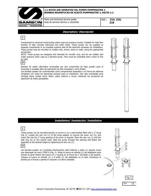
Compressed air powered reciprocating piston type low pressure pumps. Suitable for high flow<br />
transfer of high viscosity lubricants and other fluids. These pumps can be supplied as<br />
separate components or as complete systems with all the elements necessary for installation.<br />
These pumps may be mounted on mobile units, drums, tanks or walls, using the appropriate<br />
accessories.<br />
NOTE: These pumps are designed and intended for transfer only, and do not reliably stall<br />
under pressure when used as a demand pump. They must be controlled with a valve on the<br />
air inlet.<br />
SP<br />
Bombas de pistón alternativo accionadas por aire comprimido de baja presión para el<br />
transvase a caudales altos de lubricantes de alta viscosidad y otros fluidos.<br />
Las bombas pueden ser suministradas como componentes separados o en forma de sistemas<br />
completos con todos los elementos precisos para su instalación. Han sido concebidas para<br />
montaje sobre unidad móvil, bidón, sobre cisterna o mural, utilizando los accesorios de<br />
aspiración de fluido apropiados.<br />
E<br />
These pumps can be mounted directly on drums or on a wall bracket fitted with a 2” bung<br />
(Fig 2). Loosen the star nut (1) of the bung adaptor to remove the lower nut (3), and<br />
screw this into the 2” bung opening of the drum or bracket. Place the star nut (1) and the<br />
split ring (2) on the suction tube. Slide the pump through the opening and fasten the<br />
assembly at the desired height by tightening the star nut (1).<br />
SP<br />
Description/ Descripción<br />
Installation/ Instalación/ Installation<br />
Las bombas pueden ser montadas directamente sobre bidones o sobre un soporte mural<br />
que dispongan de rosca 2”BSP H (Fig. 2). Afloje la tuerca en estrella (1) del adaptador para<br />
extraer la parte inferior del mismo (2) y roscarla en el brocal de 2” del bidón o del soporte.<br />
Coloque la tuerca en estrella (1) y el anillo (2) del adaptador en el tubo, introduzca la<br />
bomba por el brocal y apriete el conjunto a la altura deseada.<br />
Ref.: 214, 216,<br />
218<br />
<strong>Samson</strong> Corporation-Swannanoa, NC 28778- 800.311.1047 www.samsoncorporation.com<br />
Fig. 2<br />
214 1
E<br />
See figure 3 for a typical installation with all the recommended accessories for the pump to operate correctly.<br />
NOTE: The compressed air supply must be between 3 and 10 bar (40 – 140 psi), 6 bar (90 psi) is the recommended pressure. An<br />
air shut-off valve must be installed, in orde r to be able to isolate the compressed air line at the end of the day (If the air inlet not<br />
is closed and there is a leakage at some point of the downstream oil circu it , the pump will start automatically , emptying the<br />
container).<br />
SP<br />
A título informativo, se muestra en la figura 3 una instalación típica con todos los elementos recomendados para su correcto<br />
funcionamiento.<br />
NOTA: La presión de alimentación de aire debe estar comprendida entre 3 y 10 bares siendo 6 bares la presión recomendada. Es<br />
aconsejable instalar, asimismo, una válvula de cierre para poder cerrar la alimentación de aire al final de la jornada (En caso de<br />
roturas o fugas en la salida de aceite, si la alimentación de aire no está cerrada, la bomba se pondría en marcha<br />
automát icamente, pudiendo vaciarse completamente el depósito).<br />
Pos Description Descripción Description Part Nº<br />
A Air shut off valve Válvula de cierre de aire Vanne d’arrêt pour ligne air 2013<br />
B Filter/Regulator Filtro Regulador Régulateur/filtre 955<br />
C Air hose Manguera de aire Flexible de liaison air 801<br />
D Quick coupler Enchufe rápido Raccord rapide 930<br />
E Air nipple Conector rápido Embout pour raccord rapide 931<br />
F 1:1 Pump <strong>PM2</strong> (200 l drum) Bomba <strong>PM2</strong> 1:1 (Bidón 200 l.) Pompe <strong>PM2</strong> 1 :1 (Fût 200 l) 218<br />
G Oil hose Manguera de aceite Flexible d’huile 867<br />
H High delivery control valve Boquerel gran caudal Pistolet verseur grand débit 1192<br />
I Bung Bushing adaptor Adaptador deslizante Bague de fixation 2029<br />
214 2<br />
Typical installation/ Conexión tipo de la bomba/ Branchement type de la pompe<br />
<strong>Samson</strong> Corporation-Swannanoa, NC 28778- 800.311.1047 www.samsoncorporation.com<br />
Fig. 3
E<br />
This pump is self–priming. To prime it the first time, you must connect the air supply to the pump and slowly increase the air<br />
pressure from 0 to the desired pressure using a pressure regulator, while keeping the outlet valve (ex. an oil control gun) open.<br />
Once oil starts to come out through the oil gun, the pump is primed.<br />
NOTE: It is important tha t the foo t valve does not come into contact with any kind of dirt or contamination like a workshop floor,<br />
because the dirt will stick to the oil on the pump and may cause subsequen t damage to the seals.<br />
SP<br />
Esta bomba es auto-cebante. Para cebarla la primera vez, es conveniente conectar el aire a la bomba incrementando la presión<br />
lentamente desde 0 bares a la presión deseada con el regulador de presión, manteniendo la válvula de salida (Ej. una pistola de<br />
aceite) abierta. Cuando el aceite empieza salir de la pistola, la bomba está cebada.<br />
NOTA: Es importante que la válvula de pie no esté en contacto con zonas sucias, tales como el suelo de un taller, porque puede<br />
entrar virutas o partículas que podrían llegar a dañar las juntas.<br />
Symptoms Possible Reasons Solutions<br />
The pump is not working or there is no Not enough air supply pressure Increase the air supply pressure<br />
oil delivery. Some outlet line component is clogged Clean or open the outlet circuit.<br />
or closed.<br />
The pump runs very fast and no oil is The drum is empty or the oil level is Replace the drum or lower the suction<br />
being delivered at the gun.<br />
beneath the suction tube inlet.<br />
tube until the inlet reaches the oil level.<br />
The pump runs on continuously after There is an oil leakage in some point of Verify and tighten or repair.<br />
the oil gun is closed.<br />
the outlet circuit.<br />
Contamination in the upper valve [(23)- Disassemble and clean. Replace if<br />
(28)] or in the foot valve [(31)-(35)]. damaged.<br />
Oil is leaking through the exhaust Oil has by-passed to the air motor Replace the packing set (17).<br />
mufflers.<br />
caused by worn or damaged packing<br />
set (17).<br />
Air is leaking through the exhaust The piston seal (11) is worn or Disassemble and clean. Replace if<br />
mufflers.<br />
damaged.<br />
damaged.<br />
The air motor dolly (1) is scratched. Replace air motor dolly (1).<br />
The air piston (8) is scratched. Replace the air piston (8).<br />
The reversing set (4) is worn or<br />
damaged.<br />
Replace the reversing set (4).<br />
The oil delivery is less than it used to Contamination in the upper valve [(23)- Disassemble and clean. Replace if<br />
be, or the flow is very uneven.<br />
(28)] or in the foot valve [(31)-(35)]. damaged.<br />
The pump operates only one cycle and The top reversing spring (2) is Replace the top reversing spring (2).<br />
then stops.<br />
damaged.<br />
Síntomas Posibles causas Soluciones<br />
La bomba no funciona o no hay entrega<br />
de aceite.<br />
La bomba empieza a bombear mucho<br />
más deprisa.<br />
La bomba sigue funcionando aunque se<br />
cierre la salida de aceite.<br />
Perdida de aceite por el silenciador del<br />
escape de aire.<br />
Perdida de aire por el silenciador del<br />
escape de aire.<br />
Disminución del caudal de entrega de<br />
aceite.<br />
La bomba empieza funcionar, pero para<br />
después de un ciclo.<br />
Operation/ Modo de empleo<br />
Troubleshooting/ Anomalías y sus soluciones<br />
Presión de suministro de aire no Incremente la presión de suministro de<br />
adecuada.<br />
aire.<br />
Algún elemento del circuito de salida Limpie o abra el circuito de salida.<br />
está obstruido o cerrado.<br />
El bidón esta vacío o el nivel de la Sustituir el bidón o calar el tubo de<br />
aceite esta por debajo de la entrada de<br />
la bomba.<br />
succión hasta llegar al nivel del aceite.<br />
Existe fuga de aceite en algún punto del<br />
circuito de salida.<br />
Verificar y apretar o reparar.<br />
Suciedad en la válvula superior [(23)- Desmontar y limpiar las válvulas. En<br />
(28)] o en la válvula de pie [(31)-(35)]. caso de deterioro, sustituirlas.<br />
Aceite ha pasado al motor de aire Sustituir el conjunto empaquetadura<br />
causado por deterioro del conjunto<br />
empaquetadura (17).<br />
(17).<br />
El collarín del vástago (11) está Sustituir el collarín del vástago (11).<br />
deteriorado.<br />
La cazoleta (1) del motor de aire está Sustituir la cazoleta (1).<br />
rayada.<br />
El vástago (8) está rayado. Sustituir el vástago (8).<br />
El conjunto inversor (4) desgastado. Sustituir el conjunto inversor (4).<br />
Suciedad en la válvula superior [(23)- Desmontar y limpiar las válvulas. En<br />
(28)] o en la válvula de pie [(31)-(35)]. caso de deterioro, sustituirlas.<br />
Rotura del muelle inversor superior (2). Sustituir el muelle inversor superior (2).<br />
<strong>Samson</strong> Corporation-Swannanoa, NC 28778- 800.311.1047 www.samsoncorporation.com<br />
214 3
E<br />
WARNING: Before starting any kind o f maintenance o r repair, disconnect the compressed air supply and open a<br />
downstream valve to relieve the oil pressure.<br />
SP<br />
ATENCIÓN: Antes de empezar cualquier tipo de mantenimiento o reparación, desconecte el aire de alimentación y<br />
accione la válvula de salida para soltar la presión del aceite.<br />
E<br />
1. Secure the pump in a vice in the horizontal position, tightening the jaws on the provided pads along the pump body.(13).<br />
2. To unscrew the suction tube (30) from the pump body (13), use a wrench on the milling (46 mm) of the foot valve body (34)<br />
(fig. 4) for stubby pump, or a rod in the holes of the foot valve body (36) for long pump.<br />
3. Remove the pin (21) located in the upper part of the connecting rod (22) (fig. 5) and unscrew the rod from the air piston (8).<br />
SP<br />
1. Fijar la bomba en una mordaza agarrando por el cuerpo de la bomba (13) con la bomba en posición horizontal.<br />
2. Para desenroscar el tubo de aspiración (31) del cuerpo de la bomba, usar llave en el fresado (46 mm) del cuerpo válvula de<br />
pie (34) (Fig. 4) para la bomba corta, o una varilla en los agujeros del cuerpo válvula de pie (36) para la bomba larga.<br />
3. Extraer el pasador (21) situado en la parte superior del eje válvula impulsión (22) (Fig. 5) y desenroscar el eje del vástago<br />
(8).<br />
214 4<br />
Repair and cleaning procedure/ Procedimientos de reparación y limpieza<br />
Separate the air motor from the pump/ Como separar el motor de aire de la bomba<br />
Fig. 4<br />
Fig. 5<br />
<strong>Samson</strong> Corporation-Swannanoa, NC 28778- 800.311.1047 www.samsoncorporation.com
E<br />
Foot valve/ Válvula de pie<br />
1. Attach the suction tube assembly to the vice (Gently!) and unscrew the foot valve<br />
body (34 stubby pump, 36 long pump) from the suction tube (30).<br />
2. Unscrew the nut (35), remove and clean the screw (31), the washer (32) and the<br />
valve body, and replace if damaged. Assemble the pump following the previous<br />
instructions, reversing each step.<br />
SP<br />
1. Fijar el conjunto tubo de succión en la mordaza y desenroscar el cuerpo válvula de<br />
pie (34 bomba corta, 36 bomba larga) del tubo de succión (30).<br />
2. Desenroscar la tuerca (35), quitar y limpiar el tornillo (31), la arandela (32) y el<br />
cuerpo válvula de pie, en caso de deterioro sustituirlos. Volver a montar en orden<br />
contrario.<br />
E<br />
1. Unscrew the nut (28) from the connecting rod (20) and remove the washer (27),<br />
the valve body (26) and o ring (25), the washer (24) and the spring (23).<br />
2. Clean and inspect these parts carefully. If any of them are damaged, replace them<br />
before reassembly.<br />
3. Assemble the pump following the previous instructions, reversing each step.<br />
SP<br />
Upper valve / Válvula de impulsión<br />
1. Desenroscar tuerca (28) del eje válvula de impulsión (20) y quitar la arandela (27),<br />
el cuerpo válvula (26) y la junta tórica (25), la arandela (24) y el muelle (23).<br />
2. Limpiar estas piezas cuidadosamente. En caso de deterioro, sustituir los elementos<br />
afectados.<br />
3. Volver a montar en orden contrario.<br />
<strong>Samson</strong> Corporation-Swannanoa, NC 28778- 800.311.1047 www.samsoncorporation.com<br />
Fig. 6<br />
Fig. 7<br />
214 5
E<br />
1. Secure the air motor body (13) in the vise and loosen the four screws (14) to<br />
remove the air motor dolly (1).<br />
2. Check the upper spring (2) and the spring stop (3) inside the air motor dolly (1).<br />
Replace if damaged.<br />
3. Remove the lower circlip (15) and muffler (16) and pull up the reversing set (4)<br />
until the hole in pump piston (8) is visible in the opening where the muffler was<br />
removed. Insert a steel rod (8 mm) in the hole to lock the piston.<br />
4. Use a prepared 17mm wrench (see fig. 9) to disassemble the inverting set (4).<br />
5. Remove the piston (8) and disassemble the circlip (9), the washers (10) and the<br />
seal (11) (fig. 10). Check the piston for scratches and replace damaged parts.<br />
6. Assemble the pump following the previous instructions, reversing each step.<br />
SP<br />
1. Fijar el cuerpo motor (13) adecuadamente y soltar los cuatro tornillos (14) para<br />
retirar la cazoleta (1).<br />
2. Verificar el muelle superior (2) y el tope muelle (3) en la cazoleta (1). Sustituir en<br />
caso de deterioro.<br />
3. Desmontar el anillo de seguridad (15) inferior y el silenciador (16) y tirar el<br />
conjunto inversor hacia arriba hasta que el agujero en el vástago (8) quede visible<br />
en la apertura donde el silenciador fue quitado. Introducir una varilla acerada<br />
(8mm) en el agujero del pistón para bloquear el mismo.<br />
4. Desenroscar el conjunto inversor (4) con una llave fija de 17mm preparada (Fig. 9).<br />
5. Quitar<br />
el vástago (8) y desmontar el anillo de seguridad (9), las arandelas (10) y el<br />
collarín (11) (Fig. 10). Verificar que el vástago no esté rayado y sustituir piezas<br />
deterioradas.<br />
6. Volver a montar<br />
en orden contrario.<br />
214 6<br />
Reversing set and air motor/ Conjunto inversor y motor de aire<br />
Fig. 9<br />
Fig. 10<br />
<strong>Samson</strong> Corporation-Swannanoa, NC 28778- 800.311.1047 www.samsoncorporation.com<br />
Fig. 8
E<br />
1. Follow the above procedure for the air motor until the air piston<br />
(8) has been removed from the air motor body.<br />
2. Remove the circlip (18) and the packing set ( 17) from the air<br />
motor body (13). Replace if damaged.<br />
3. Assemble the pump following the previous<br />
instructions, reversing<br />
each step.<br />
4. NOTE: The packing set is directional. It is not marked and must<br />
be installed correctly or it will leak. Look carefully at the inside<br />
diameter of the seal, you will see three components. The middle<br />
black ring that is split is a bearing. Above and below it are the<br />
brownish Turcite® seals, these are made with a step, and the<br />
step faces the oil. Confirm this by looking into the seal from both<br />
directions, from one side you will not see the steps, and from the<br />
other you will; this is the side that faces the oil. See Figure 11a.<br />
SP<br />
Packing set/ Conjunto empaquetadura<br />
1.<br />
Seguir el procedimiento del motor de aire hasta haber extraído el<br />
vástago (8) del cuerpo motor.<br />
2. Quitar el anillo de seguridad (18)<br />
y el conjunto empaquetadura<br />
(17) del cuerpo motor de aire (13). Sustituir en caso de deterioro.<br />
3. Volver a montar en orden contrario.<br />
Fig. 11a<br />
Fig. 11a<br />
<strong>Samson</strong> Corporation-Swannanoa, NC 28778- 800.311.1047 www.samsoncorporation.com<br />
Fig. 11<br />
214 7
214 8<br />
Parts list/ Lista de recambios<br />
<strong>Samson</strong> Corporation-Swannanoa, NC 28778- 800.311.1047 www.samsoncorporation.com<br />
835801 7<br />
Stub<br />
Corta<br />
Courte<br />
Long<br />
Larga<br />
Longue
Repair Kits/ Kits de reparación<br />
Part. No. Description Descripción Include pos.<br />
AK-4 Air motor Motor de aire 2-7, 12, 19<br />
AK-5 Packing set and seals Conjunto empaquetadura y<br />
juntas<br />
9, 11, 12, 17- 19, 25<br />
Parts available separately/ Piezas disponibles por separado<br />
Pièces disponibles séparément<br />
Part Nº<br />
Cód./ Réf.<br />
Pos Description Descripción Description<br />
735100 1 Air Motor Cylinder Cazoleta Cassolette<br />
835302 2 Upper Spring Resorte Superior Ressort Supérieur<br />
735230 3 Spring Button Botón Del Resorte Bouton De Ressort<br />
735216 4 Air Motor Assembly Pistón de aire Piston d’air<br />
835301 5 Lower Spring Baje El Resorte Abaissez Le Ressort<br />
735217 6 Spacer Espaciador Entretoise<br />
735218 7 Washer Arandela Rondelle<br />
735219 8 Pump Piston Vástago Tige<br />
942745 9 Upper Snap Ring Anillo Rápido Superior Anneau ressort Supérieur<br />
735211 10 Seal Support Washer Arandela De la Ayuda De Rondelle De Support Du<br />
Sello<br />
joint<br />
946501 11 Air Piston Seal Sello Del Pistón Del Aire Joint De Piston D'Air<br />
946026 12 Air Cylinder O-ring Junta tórica Joint torique<br />
735103 13 Pump Body NPT Cuerpo De Bomba NPT Corps De la Pompe NPT<br />
940321 14 Air Cylinder Bolt Perno Del Cilindro Del Aire Boulon De Cylindre D'Air<br />
942730 15 Muffler Snap Ring Anillo Rápido Del<br />
Anneau ressort De<br />
Silenciador<br />
Silencieux<br />
835400 16 Muffler Silenciador Silencieux<br />
735210 17 Packing Set Cjto empaquetadura Ensemble porte-joints<br />
942747 18 Lower Snap Ring Baje El Anillo Rápido Abaissez L'Anneau ressort<br />
810501 19 Square Cut Seal<br />
735208 20 Connecting Rod 1:1 Varilla alargadora 1:1 Tige de connexion 1 :1<br />
943041 21 Upper Roll Pin Perno De Rodillo Superior Goupille De Rouleau<br />
943042 22 Lower Roll Pin Perno De una Bobina Más Supérieur Goupille De<br />
inferior<br />
Rouleau Plus inférieur<br />
835300 23 Check Spring Compruebe El Resorte Vérifiez Le Ressort<br />
735206 24 Check Plate 1:1 Compruebe La Placa 1:1 Vérifiez La Plat 1:1<br />
946023 25 Plunger Body O-Ring 1:1 Junta Tórica 1:1 Joint Torique 1 :1<br />
735207 26 Plunger Body 1:1 Cuerpo Del Émbolo 1:1 Corps De Plongeur 1:1<br />
735408 27 Washer 1:1 Asiento De Válvula 1:1 Siège de Valve 1:1<br />
941008 28 Plunger Body Nut Tuerca Del Cuerpo Del Écrou De Corps De<br />
Émbolo<br />
Plongeur<br />
2029 29 Bung Adaptor 1:1 Adaptador Deslizante Fausse Bonde<br />
735204 30 Suction Tube 1:1 Tubo 1:1 De la Succión Tube 1:1 D'Aspiration<br />
735214 31 Foot Valve Bolt Perno De la Válvula De Pie Boulon De Soupape<br />
d'aspiration<br />
735206 32 Foot Valve Plate Placa De la Válvula De Pie Plat De Soupape<br />
d'aspiration<br />
946025 33 Foot Valve O-Ring Anillo o De la Válvula De Bague De Soupape<br />
Pie<br />
d'aspiration<br />
735229 34 Foot Valve Body Cuerpo De Válvula De Pie Corps De Soupape<br />
d'aspiration<br />
941108 35 Foot Valve Nut Tuerca De la Válvula De Pie Écrou De Soupape<br />
d'aspiration<br />
<strong>Samson</strong> Corporation-Swannanoa, NC 28778- 800.311.1047 www.samsoncorporation.com<br />
214 9
Maximum Air Pressure Presión de aire máxima Pression Atmosphérique Maximum 10 bar (140 psi)<br />
Minimum Air Pressure Presión de aire mínima Pression atmosphérique Minimum 3 bar (40 psi)<br />
Maximum Delivery Caudal máximo La Livraison Maximum 60 l/min 15GPM<br />
Air Inlet Thread Rosca entrada aire Fil D'Entrée D'Air 1/4" NPT (F)<br />
Oil Outlet Thread Rosca salida aceite Fil De Sortie D'Huile 3/4" NPT (F)<br />
Air Piston Diameter Diámetro pistón de aire Diamètre De Piston D'Air 50 mm (2”)<br />
Air Piston Stroke Recorrido del pistón de aire Course De Piston D'Air 100 mm (4”)<br />
Model/ Modelo A (mm) B (mm) C (mm) D (mm) Weight(kg)/ LBS<br />
IN<br />
IN<br />
IN<br />
IN<br />
(Kg.)<br />
214 23.25 (590) 14.5 (365) 2 (52) 8.5 (215) 7.6 (3.45)<br />
216 41.7 (1060) 14.5 (365) 2 (52) 27.3 (695) 11 (5.00)<br />
218 50.6 (1285) 14.5 (365) 2 (52) 35.8 (910) 12.9 (5.85)<br />
214 10<br />
Technical data/ Datos técnicos<br />
Dimensions/ Dimenciones<br />
Fig. 12<br />
<strong>Samson</strong> Corporation-Swannanoa, NC 28778- 800.311.1047 www.samsoncorporation.com
CAPACITY CURVE<br />
CURVE DE CAPACIDAD<br />
COURBE DE CAPACITÉ<br />
Pump PM 2 1: 1<br />
Bomba PM 2 1:1<br />
Pompe PM 2 1/1<br />
Technical properties/ Condiciones técnicas/ Conditions techniques<br />
Fluid/ Fluido/ Fluide 20W Oil<br />
Water temperature/ Temperatura agua/ Température de l’eau 20ºC (68ºF)<br />
Suction extention tube 700 mm/ Tubo prolongador 700 mm/ Tube d’aspiration 700 mm<br />
1. Air inlet pressure/ Presión entrada aire/ Pression entrée d’air 6 bar (84 psi)<br />
2. Air inlet pressure/ Presión entrada aire/ Pression entrée d’air 4,5 bar (63 psi)<br />
3. Air inlet pressure/ Presión entrada aire/ Pression entrée d’air 3 bar (42 psi)<br />
<strong>Samson</strong> Corporation-Swannanoa, NC 28778- 800.311.1047 www.samsoncorporation.com<br />
214<br />
216<br />
218<br />
214 11
214 12<br />
Distributed by:<br />
<strong>Samson</strong> Corporation-Swannanoa, NC 28778- 800.311.1047 www.samsoncorporation.com