Mejora de la Eficiencia en los Generadores Empleados en Parques ...
Mejora de la Eficiencia en los Generadores Empleados en Parques ...
Mejora de la Eficiencia en los Generadores Empleados en Parques ...

You also want an ePaper? Increase the reach of your titles
YUMPU automatically turns print PDFs into web optimized ePapers that Google loves.
Tesis Doctoral: <strong>Mejora</strong> <strong>de</strong> <strong>la</strong> <strong>Efici<strong>en</strong>cia</strong> <strong>en</strong> <strong>los</strong> G<strong>en</strong>eradores <strong>Empleados</strong> <strong>en</strong> <strong>Parques</strong> Eólicos<br />
Utilizando Contro<strong>la</strong>dores “Fuzzy” Adaptativos<br />
Pérdidas <strong>en</strong> Conducción: La pot<strong>en</strong>cia disipada <strong>en</strong> <strong>los</strong> IGBTs es dada por <strong>la</strong><br />
ecuación (2.20).<br />
( V −V<br />
)<br />
⎛ m<br />
⎛ 1 m ⎞<br />
Cr = ⎜ +<br />
+ ⎜ + ⋅ cosφ⎟<br />
⋅VCEO<br />
⋅ I<br />
⎝<br />
⎝ 2π<br />
8 ⎠<br />
1 ⎞ CEN CEO 2<br />
⎟ ⋅<br />
⋅ I CM<br />
8 3π<br />
⎠ I CN<br />
Página 24 <strong>de</strong> 195 Durval <strong>de</strong> Almeida Souza<br />
CM<br />
(2.21)<br />
Don<strong>de</strong> VCEN es <strong>la</strong> t<strong>en</strong>sión nominal <strong>de</strong> saturación, ICN es <strong>la</strong> corri<strong>en</strong>te nominal <strong>de</strong>l<br />
colector, m es el índice <strong>de</strong> modu<strong>la</strong>ción, VCEO es <strong>la</strong> t<strong>en</strong>sión <strong>de</strong> frontera <strong>en</strong>tre el<br />
colector y emisor, ICM es <strong>la</strong> corri<strong>en</strong>te máxima <strong>en</strong> <strong>la</strong> carga y ϕ es el ángulo <strong>de</strong><br />
<strong>de</strong>sp<strong>la</strong>zami<strong>en</strong>to.<br />
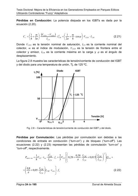
La figura 2.8 muestra <strong>la</strong>s características <strong>de</strong> t<strong>en</strong>sión/corri<strong>en</strong>te <strong>de</strong> conducción <strong>de</strong>l IGBT<br />
y <strong>de</strong>l diodo para una temperatura <strong>de</strong> unión, Tj, <strong>de</strong> 125 ºC.<br />
Ic [%]<br />
100<br />
V<br />
50<br />
0<br />
Diodo IGBT<br />
TJ = 125 o C<br />
VFO 1 2 3 4<br />
VCE<br />
T<strong>en</strong>sión [V]<br />
Fig. 2.8 – Características <strong>de</strong> t<strong>en</strong>sión/corri<strong>en</strong>te <strong>de</strong> conducción <strong>de</strong>l IGBT y <strong>de</strong>l diodo.<br />
Pérdidas por Conmutación: Las pérdidas por conmutación son <strong>de</strong>bidas a <strong>la</strong>s<br />
condiciones <strong>de</strong> <strong>en</strong>trada <strong>en</strong> conducción (“turn-on”) y <strong>de</strong> bloqueo (“turn-off”). Las<br />
ecuaciones (2.22) y (2.23) repres<strong>en</strong>tan <strong>la</strong>s pérdidas <strong>de</strong> conmutación “turn-on” y<br />
“turn-off”, respectivam<strong>en</strong>te.<br />
⎡⎛<br />
⎢⎜<br />
0,<br />
38 I<br />
0,<br />
28 + ⋅<br />
⎢⎜<br />
π I<br />
⎣⎝<br />
2<br />
2<br />
1 ICM<br />
2<br />
CM<br />
CM<br />
turn−on<br />
= VCC<br />
⋅t<br />
rn ⋅ ⋅ fc<br />
+ VCC<br />
rrn<br />
8 ICN<br />
3<br />
CN<br />
CN<br />
P<br />
⎛ 0,<br />
8 I<br />
+<br />
⎜ + 0,<br />
05⋅<br />
⎝ π I<br />
⎞<br />
⎟<br />
⎠<br />
⎤<br />
CM<br />
⎟<br />
ICM<br />
⋅t<br />
rrn ⎥ ⋅ fc<br />
CN<br />
⎦<br />
⎛ I<br />
+ 0,<br />
015 ⎜<br />
⎝ I<br />
⎞<br />
⎟<br />
⎠<br />
⎞<br />
⎟Q<br />
⎟<br />
⎠<br />
+<br />
(2.22)