D126-0115A ITAS Installation Instruction - Hirschmann Car ...
D126-0115A ITAS Installation Instruction - Hirschmann Car ...
D126-0115A ITAS Installation Instruction - Hirschmann Car ...

Create successful ePaper yourself
Turn your PDF publications into a flip-book with our unique Google optimized e-Paper software.
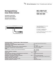
1. Mounting example and procedure / Ejemplo de montaje y procedimiento<br />
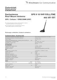
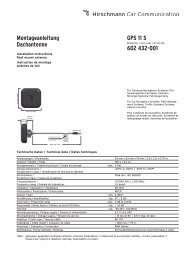
Vehicle roof mounting / Montaje en techo del vehiculo<br />
Mounting requirements and restrictions<br />
Choose appropriate mounting location on flat surface (see Sketch #1) .<br />
Max. tolerable mounting material thickness 3 mm/ 0.118 in.<br />
Safely drill 15 mm/ 0.6 in. mounting hole at desired location (see Sketch #2)<br />
Unscrew mounting nut (see Sketch #3)<br />
Insert threaded antenna mounting stud through mounting hole (see Sketch #4)<br />
Slide slotted mounting nut on and screw back on to antenna mounting stud.<br />
Maximum tightening torque is 5Nm.<br />
Sketch #1—Select Mounting Location/<br />
Seleccionar área de montaje<br />
2. Technical data / Datos Técnicos<br />
Dimensions / Dimensiones 124mm x 80mm x 31mm / 4.9 x 3.1 x 1.22 in.<br />
Weight / Peso ca. 500 g / 17.6 oz.<br />
Temperature range / Rango de Temperatura -40°C to +85°C / -40°F to +185°F<br />
Protection class / ĺndice de protección IP66 (acc. IEC 60529)<br />
ESD Protection / Protección ESD<br />
IRIDIUM Antenna<br />
± 15 kV<br />
Frequency range / Rango de frecuencia 1616 - 1626.5 MHz<br />
Gain / Ganancia 3 dBic²<br />
Polarization / Polarización RHCP<br />
Axial ratio / Proporción axial < 4 dB<br />
Lightning protection / Protección contra relámpagos<br />
Iridium Communication<br />
DC grounded<br />
Transmit power / Poder de transmisión 1.6W ¹<br />
Max. message size / Tamaño máximo de mensaje Tx 340 Bytes, Rx 270 Bytes ¹<br />
Latency / Estado latente<br />
Data Interfaces / Interface datos<br />
20 sec (typ)¹<br />
Type / tipo 1 serial RS-232C<br />
Connector / Conector M12/8P male; M12/10P male for engineering samples only<br />
Cable length / Longitude del cable<br />
Power / Potencia eléctrica<br />
Embedded connector or 254mm pigtail; extension cables available<br />
Voltage supply / Suministro de voltaje 8-32 VDC or 5 VDC regulated (depending on product version)<br />
Current consumption / Consumo de corriente 1 Amp max transmit; tbd. stand-by; on/off signal line<br />
Transient protection / Protección transitoria<br />
Reverse Voltage protection / Protección de voltaje<br />
SAE J1113/11/12 (only for 8-32 VDC supply power product version)<br />
24V tested<br />
¹ according to Iridium 9602 Modem Specification and subject to change /<br />
De acuerdo a especificaciones del modem Iridium 9602 y sujetas a cambio<br />
² dBic: referenced to an isotropic radiator, circular polarization / hace referencia a un radiador isotropico, polarización circular<br />
Requerimientos y restricciones para montaje<br />
Seleccione el lugar apropiado – superficie plana – para montar (ver Sketch #1).<br />
El espesor/grosor máximo tolerable del material a montarse es de 3 mm / 0.118<br />
pulgadas<br />
Taladre con precaución el hoyo para montaje con un diámetro de 15 mm / 0.6<br />
pulgadas en el lugar seleccionado (ver Sketch #2)<br />
Desatornille la tuerca de montaje de la antena (ver Sketch #3)<br />
Introduzca la rosca de la base de la antena a través del hoyo de montaje (ver<br />
Sketch #4)<br />
Deslice la tuerca de montaje y atornille en la rosca de la base de la antena<br />
El par máximo (torque) de apriete es 5Nm.<br />
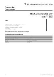
Pin Male M12/8 on antenna module<br />
1 Chassis Gnd<br />
2 Signal Gnd<br />
3 Rx (see note)<br />
4 Tx (see note)<br />
5 Power in<br />
6 On/Off Control<br />
7 Network status<br />
8 Tamper detect<br />
Sketch #2—Required Mounting hole/<br />
Hoyo requerido para montaje<br />
Sketch #3—Mounting Nut/<br />
Tuerca de montaje<br />
27 mm<br />
1 1/16 in<br />
Sketch #4—Mount in hole/<br />
Antena montada en hoyo<br />
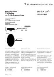
Extension cable with mating<br />
M12/8P female connector<br />
connects to antenna base<br />
Sketch #5—Pin-Outs<br />
Slotted nut slides<br />
over mounting stud.<br />
24 AWG recommended wire gauge for extension cable.<br />
24 CAE calibre de alambre estadounidense recomendado<br />
para cables de extension<br />
Antenna module<br />
M12/8P male<br />
Mating connector on<br />
connecting cable<br />
M12/8P female<br />
Note: The antenna module carries a M12/8P male connector.<br />
The Rx and Tx pins are relative to the antenna module.<br />
<strong>D126</strong>-<strong>0115A</strong> p2