Create successful ePaper yourself
Turn your PDF publications into a flip-book with our unique Google optimized e-Paper software.
• Ingresso video:1Vpp(da 0,7 a<br />
2Vpp) da linea coassiale; V+<br />
0,6Vpp, V– 0,6 Vpp (da 0,3 a<br />
0,9Vpp) da linea differenziale (doppino<br />
telefonico).<br />
• Impedenza d’ingresso video:<br />
≥22kΩ<br />
• Segnale di chiamata: bitonale per<br />
chiamate provenienti dal posto<br />
esterno (e chiamate dal pianerottolo)<br />
e a nota continua per chiamate<br />
interne (<strong>VMF</strong>/<strong>203</strong>).<br />
• Segreto di conversazione verso il<br />
posto esterno (<strong>VMF</strong>/<strong>203</strong>).<br />
• Temperatura di funzionamento: da 0<br />
°C a +35 °C.<br />
• Dimensioni: 195x230x72mm.<br />
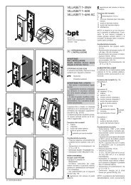
Il fusibile F1 di protezione tipo T<br />
500mA è situato sul circuito stampato<br />
(fig. 7-8).<br />
(Fusibile: F = rapido, T = ritardato).<br />
NOTA. Effettuare i collegamenti all’apparecchio<br />
seguendo gli schemi di<br />
impianto realizzati con il monitor<br />
VM/<strong>200</strong> o VM/<strong>203</strong>.<br />
ATTENZIONE. Si raccomanda di<br />
installare il monitor in ambiente<br />
asciutto.<br />
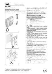
Istruzioni per l’installazione<br />
Spostare il dispositivo di bloccaggio<br />
come indicato in fig. 3. Sfilare il supporto<br />
in acciaio dal monitor e fissarlo<br />
ad un’altezza adatta all’utente<br />
mediante i tasselli e viti in dotazione.<br />
Rispettare l’indicazione ALTO e fare in<br />
modo che l’uscita dei cavi dalla parete<br />
coincida con l’apposito passaggio<br />
del supporto (fig. 4).<br />
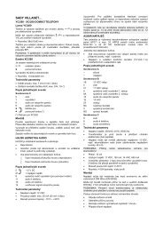
Svitare le due viti di fissaggio e togliere<br />
la parte sinistra del mobile (fig. 5).<br />
Passare i conduttori attraverso la feritoia<br />
sul fondo del monitor, posizionare<br />
il monitor nel supporto da parete ed<br />
innestarlo al supporto stesso con un<br />
movimento verso il basso (fig. 6).<br />
Per evitare cadute del monitor a<br />
causa di urti accidentali, bloccare il<br />
monitor stesso al supporto da parete<br />
spostando verso destra il dispositivo<br />
di bloccaggio.<br />
Procedere nella maniera opposta in<br />
caso di smontaggio del monitor.<br />
Effettuare i collegamenti e rimettere la<br />
parte sinistra del mobile fissandola<br />
con le due viti.<br />
GB INSTALLATION<br />
INSTRUCTIONS<br />
WARNING FOR THE INSTALLER<br />
These instructions should be attached<br />
to the receiver.<br />
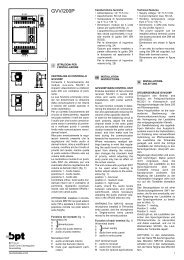
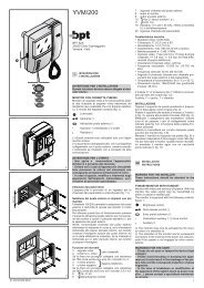
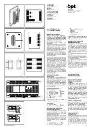
<strong>VMF</strong>/<strong>200</strong> FLAT MONITOR WITH<br />
HANDSET WALL MOUNTED VER-<br />
SION<br />
Monitor with video and secrecy of<br />
speech. With this monitor, the video<br />
signal may be transmitted by either a<br />
coaxial or a twisted pair.<br />
Can be converted in table-top version<br />
using the VKT/<strong>203</strong>F kit.<br />
<strong>VMF</strong>/<strong>200</strong>, figure 1, is equipped with<br />
the following controls:<br />
ON/OFF-brightness control<br />
(side thumbweel D) ( 1 )<br />
Entry panel activation ( 1 )<br />
•/ Auxiliary or stairs light control<br />
(can be selected using the<br />
SW4 switch, figure 7-8) ( 2 )<br />
NOTE. The monitor is supplied<br />
with SW4 switch in stair<br />
light position.<br />
Door release control ( 2 )<br />
(<br />
2<br />
1 ) The activation of the monitor and its<br />
subsequent connection to the external<br />
entry panel, are only possible if the<br />
system is not engaged by other conversations.<br />
( 2 ) The stairs light and door release<br />
controls may only be activated by the<br />
monitor when it is switched on.<br />
WARNINGS FOR THE USER<br />
- Please do not open or tamper the<br />
device (high voltage!).<br />
- Please avoid knocking or bumping<br />
the apparatus as it could result in<br />
the breakage of the picture tube and<br />
the consequent projection of glass<br />
fragments.<br />
- In the case of breakdown or modification<br />
of the apparatus of the<br />
system (such as power supplier ...)<br />
please contact a specialized maintenance<br />
service.<br />
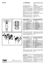
Personal door-bell button<br />
The monitor is fitted with a differentiated<br />
call input (i.e.: for calls from landing<br />
and external entry panel) a twotone<br />
call, figure 9.<br />
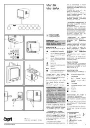
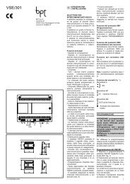
<strong>VMF</strong>/<strong>203</strong> MONITOR WITH INTER-<br />
COM AND HANDSET WALL MOUN-<br />
TED VERSION<br />
This monitor has the same features<br />
and controls as the <strong>VMF</strong>/<strong>200</strong> model,<br />
but is also equipped with 3 buttons for<br />
communication with other intercom<br />
units, and a red LED which indicates<br />
when the line is busy, figure 2.<br />
The monitor permits to identify the<br />
source of a call: a continuous call tone<br />
identifies calls from other intercom<br />
units and a two-tone call identifies<br />
calls from the external entry panel (or<br />
from the landing).<br />
A call from the entry panel during an<br />
internal conversation between two<br />
intercom units is indicated by the activation<br />
of the monitor and the emission<br />
of a low acoustic signal.<br />
In this case, communication with the<br />
entry panel (and hence the possibility<br />
of activating both the door release<br />
control and the stairs light relay)<br />
may be established by hanging the<br />
handset of the intercom unit currently<br />
in use and lifting the handset of the<br />
one signalling a call.<br />
The monitor requires the use of<br />
VSE/<strong>200</strong>.01 selector.<br />
Entry panel selection in systems<br />
with several entrances<br />
If the system foresee more than one<br />
entry panel, set the SW/4 switch, figure<br />
7-8, to the stairs light position to<br />
select this option.<br />
The VSI/<strong>200</strong> selector allows you to<br />
select the external entry panel or camera<br />
from the monitor in sequential mode.<br />
To operate the selector: press the<br />
entry panel activation button to turnon<br />
the monitor; and then press the<br />
stair light control button to select the<br />
entry panels.<br />
NOTE. In the event a call is made from<br />
the entry panel, the selection in progress<br />
is interrupted.<br />
If the external call is addressed to the<br />
monitor making the selection, the<br />
monitor displays the image filmed at<br />
the external entry from where the call<br />
is addressed to another monitor, the<br />
image disappears from the monitor.<br />
Function of each terminal<br />
3÷11 and 20: terminals for connection<br />
of standard <strong>VMF</strong>/<strong>200</strong> monitor<br />
3÷20: terminals for connection of<br />
<strong>VMF</strong>/<strong>203</strong> monitor with intercom facility<br />
3 video signal coaxial<br />
4 video signal shield cable<br />
If the video line ends at this monitor,<br />
connect a 75Ω (violet-green-black-gold)<br />
resistor between terminals 3 and 4.<br />
3 pos. video signal twisted<br />
4 neg. video signal pair<br />
If the video line ends at this monitor,<br />
connect a 56Ω (green-blue-black-gold)<br />
resistor between terminals 3-5 and 4-5.<br />
5 – 14,5÷17,5V<br />
6 + supply voltage to monitor<br />
7 call input from entry panel<br />
8 audio to monitor<br />
9 audio to entry panel<br />
10 Aux - auxiliary services<br />
11 (24V 1A) ( 1 )<br />
12 call input from intercom receiver<br />
13 call common intercom receivers<br />
14 call to receiver no. 1<br />
15 call to receiver no. 2<br />
16 call to receiver no. 3<br />
17 engaged<br />
18 stairs light ( 2 )<br />
19 auto-switch on<br />
20 call input from landing<br />
( 1 ) This function is enabled by setting<br />
the SW4 switch, figure 7-8, to the auxiliary<br />
control position Aux • .<br />
( 2 ) This function is enabled by setting<br />
the SW4 switch, figure 7-8, to the stairs<br />
light position .<br />
Technical features<br />
• Picture screen: 4” (10 cm).<br />
• Supply voltage: 14,5÷17,5VDC<br />
• Current demand: 400mA max. (8mA<br />
quiescent).<br />
• Bandwidth response at -3dB: 5MHz.<br />
•Video input: 1Vpp (0,7 to 2Vpp) from<br />
coaxial line; + video signal 0,6Vpp, -<br />
video signal 0,6Vpp (0,3 to 0,9 Vpp)<br />
from differential line (twisted pair).<br />
•Video input impedance: ≥22kΩ.<br />
• Call signal: two-tone call signal at entry<br />
panel (and at personal door-bell button)<br />
and continuous tone call signal<br />
for internal calls (<strong>VMF</strong>/<strong>203</strong>).<br />
• Audio secrecy to entry panel<br />
(<strong>VMF</strong>/<strong>203</strong>).<br />
• Working temperature range: from 0 °C<br />
to +35 °C.<br />
• Dimensions: 195x230x72mm.<br />
The monitor is protected by the slow<br />
blow fuse F1 - T 500mA - located on<br />
monitor’s printed card, figures 7-8.<br />
(Fuse: F = fast, T = slow).<br />
NOTE. Connect wires to terminals in<br />
accordance to VM/<strong>200</strong> or VM/<strong>203</strong><br />
wiring diagrams.<br />
WARNING. It is recommended to<br />
install the monitor in a dry place.<br />
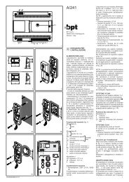
Installation instructions<br />
Slide the locking latch as shown in<br />
figure 3. Slide the steel frame out, and<br />
fix it on the wall at a suitable height by<br />
using the screws and retainers included<br />
in the pack.<br />
Please, pay attention to place the<br />
frame with the indication TOP in upper<br />
position, and make the hole, figure 4,<br />
to coincide with the cable junction<br />
box.<br />
Unscrew the two screws, figure 5, and<br />
take the left part of the housing out.<br />
Pass the cables through the slot at the<br />
bottom of the housing, place the monitor<br />
on the steel frame and fix it by sliding<br />
it downwards, figure 6.<br />
To avoid undesired falls of the monitor<br />
caused by accidental shocks, lock it<br />
by sliding the latch to the right.<br />
Proceed the opposite way to unmount<br />
the monitor. Make all the connections<br />
and fix the cover of the left part of the<br />
housing with the two screws.<br />
D INSTALLATIONS-<br />
ANLEITUNG<br />
ACHTUNG!<br />
NUR FÜR INSTALLATEUR<br />
Diese Anleitungen müßen jede der<br />
Sprechstelle begleiten.<br />
FLACHMONITOR MIT HÖRER<br />
<strong>VMF</strong>/<strong>200</strong> WANDAUSFÜHRUNG<br />
Monitor Mitseh- und Mithörgesperrt<br />
für den Videosignalempfang über<br />
Koaxial- oder Telefonkabel.<br />
Kann mit dem entsprechenden<br />
Montage Kit VKT/<strong>203</strong>F auch als<br />
Tischausführung verwendet werden.<br />
Mit folgenden Schaltelementen (Abb. 1):<br />
EIN/AUS, Helligkeit (seitlich<br />
angeordnete Knopf D) ( 1 ).<br />
Außenstationeneinschaltung ( 1 )<br />
•/ Zusatzsteuerung oder Treppenlicht<br />
(mittels Umschalter<br />
SW4 wählbar, Abb. 7-8)( 2 )<br />
ANMERKUNG. Der monitor ist<br />
mit Unschalter SW4 auf<br />
Treppenlicht Position geliefert.<br />
Türöffnertaste ( 2 )<br />
( 1 ) Die Einschaltung des Gerätes und<br />
der anschließende Anschluß an die<br />
Außenstation sind nur möglich, wenn<br />
die Anlage nicht besetzt ist.<br />
( 2 ) Treppenlicht und Türöffner sind nur<br />
bei eingeschaltetem Monitor schaltbar<br />
HINWEISE FÜR DEN NUTZER<br />
- Bitte Gerät nicht öffnen oder aufbrechen<br />
(hohe Spannung!).<br />
- Zur Vermeidung eines Bildröhrenbruchs,<br />
Stösse und Schläge unterlassen.<br />
- Bei Störungen, Änderungen oder<br />
Reparaturen an den Geräten (Netzgerät,<br />
usw.) nur an Spezialisten<br />
wenden.<br />
Etagenanruf<br />
Das Gerät verfügt über einen Eingang<br />
für die Anruf unterscheidung (z.B.<br />
Etagenanruf) mit Zweiklangton (Abb.<br />
9).<br />
INTERCOM-FLACHMONITOR<br />
MIT HÖRER <strong>VMF</strong>/<strong>203</strong><br />
WANDAUSFÜHRUNG<br />
Eigenschaften und Bedienelemente<br />
wie <strong>VMF</strong>/<strong>200</strong>, jedoch zusätzlich mit 3<br />
Tasten für den Anruf anderer<br />
Innensprechstellen und einen roten<br />
LED für die Besetztanzeige (Abb. 2).<br />
Das Gerät macht die Herkunft des<br />
Anrufes erkennbar durch Dauerton<br />
für Anrufe von anderen Intercom-<br />
Stellen und Zweiklangton für Anrufe<br />
von der Außenstation (oder von der<br />
Etage).<br />
Ein Anruf von der Außenstation während<br />
eines Gespräches zwischen<br />
Innensprechstellen wird durch die<br />
Einschaltung des Monitors sowie<br />
eines schwachen Tonsignals im Hörer<br />
angezeigt.<br />
In diesem Fall kann das Gespräch mit<br />
der Außenstation (und damit die<br />
Betätigung des Türöffners und des<br />
Treppenlichtes) durch Auflegen der<br />
Hörer und Abheben des Hörers an<br />
der angerufenen Innensprechstelle<br />
aufgenommen werden.<br />
Der monitor benötigt den Gebrauch<br />
des Wählers VSE/<strong>200</strong>.01.<br />
Auswahl der Außenstation bei<br />
Anlagen mit mehreren Eingängen<br />
Sollte die Anlage mehr als eine<br />
Außenstelle vorsehen und diese<br />
gewählt werden, ist der Umschalter<br />
SW/4 (Abb. 7-8) auf Position Treppenlicht<br />
zu stellen.<br />
Der Wahlschalter VSI/<strong>200</strong> ermöglicht<br />
die Auswahl der Außenstation oder<br />
des Aufnahmegeräts über den<br />
Bildschirm auf sequentielle Weise.<br />
Um diese Betriebsart einzuschalten,<br />
die Taste Einschalten Außenstation<br />
betätigen, um den Monitor einzuschalten,<br />
und danach die Taste<br />
Treppenbeleuchtung zwecks Auswahl<br />
der Außenstationen.<br />
HINWEIS. Ein eventuell von der<br />
Außenstation kommender Ruf unterbricht<br />
den Auswahlvorgang und, falls<br />
der Ruf für die gleiche interne<br />
Nebenstelle bestimmt ist, erscheint<br />
auf dem Bildschirm das Bild, das an<br />
der Außenstation aufgenommen<br />
wurde, von der aus der Ruf erfolgt ist.<br />
Sollte der Ruf dagegen für eine andere<br />
interne Nebenstelle bestimmt sein,<br />
so verschwindet das Bild vom<br />
Bildschirm.<br />
Belegung der Klemmleiste<br />
3÷11 und 20: Klemmen für den<br />
Anschluß des Standardmonitors<br />
<strong>VMF</strong>/<strong>200</strong><br />
3÷20: Klemmen für den Anschluß des<br />
Intercom-Monitors <strong>VMF</strong>/<strong>203</strong>