
You also want an ePaper? Increase the reach of your titles
YUMPU automatically turns print PDFs into web optimized ePapers that Google loves.
D<br />
D<br />
07.<strong>200</strong>4/2403-3500<br />
3<br />
2<br />
1<br />
2<br />
3<br />
1<br />
1<br />
LED<br />
2<br />
3<br />
4<br />
SW4<br />
F1<br />
SW4<br />
F1<br />
CP<br />
B<br />
B<br />
20<br />
11<br />
10<br />
987<br />
6<br />
5<br />
4 3<br />
AUX<br />
20<br />
11<br />
10<br />
987<br />
6<br />
5<br />
4 3<br />
AUX<br />
12<br />
13<br />
14<br />
15<br />
16<br />
17<br />
18<br />
19<br />
<strong>VMF</strong>/<strong>200</strong>(<strong>VMF</strong>/<strong>203</strong>)<br />
3<br />
4<br />
5<br />
6<br />
7<br />
8<br />
9<br />
10<br />
11<br />
20<br />
C<br />
5<br />
6<br />
8<br />
9<br />
D<br />
3<br />
4<br />
7<br />
B<br />
5<br />
6<br />
21<br />
8<br />
8A<br />
22<br />
11<br />
12<br />
23<br />
14<br />
13<br />
16<br />
VA/<strong>200</strong><br />
2<br />
A<br />
1<br />
5<br />
6<br />
7<br />
8<br />
9<br />
<strong>VMF</strong>/<strong>200</strong><br />
<strong>VMF</strong>/<strong>203</strong><br />
BPT SpA<br />
30020 Cinto Caomaggiore<br />
Venezia - Italy<br />
I<br />
ISTRUZIONI PER<br />
L’INSTALLAZIONE<br />
AVVERTENZE PER<br />
L’INSTALLATORE<br />
Queste istruzioni devono essere<br />
allegate al derivato interno.<br />
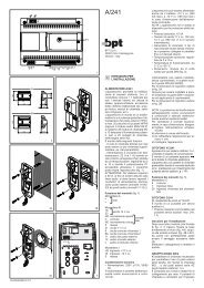
MONITOR PIATTO CON<br />
CORNETTA <strong>VMF</strong>/<strong>200</strong> DA PARETE<br />
Monitor con segreto video e di conversazione<br />
adatto alla ricezione di<br />
segnale video trasmesso sia mediante<br />
cavo coassiale che con doppino<br />
telefonico.<br />
L’apparecchio può essere utilizzato in<br />
versione da tavolo abbinato al kit<br />
VKT/<strong>203</strong>F.<br />
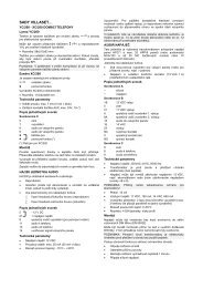
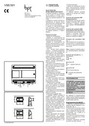
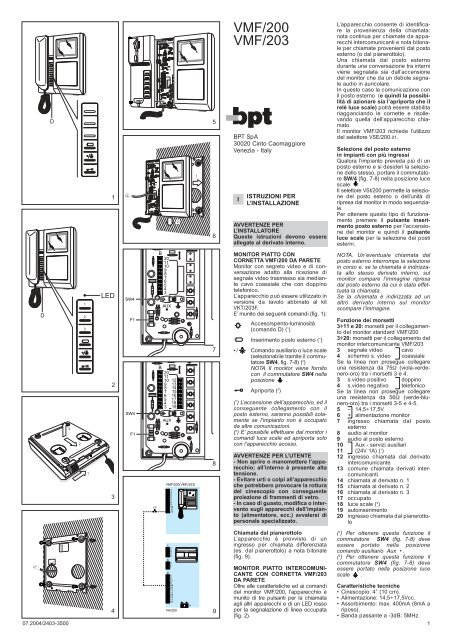
E’ munito dei seguenti comandi (fig. 1):<br />
Acceso/spento-luminosità<br />
(comando D) ( 1 )<br />
Inserimento posto esterno ( 1 )<br />
•/ Comando ausiliario o luce scale<br />
(selezionabile tramite il commutatore<br />
SW4, fig. 7-8) ( 2 )<br />
NOTA. Il monitor viene fornito<br />
con il commutatore SW4 nella<br />
posizione .<br />
Apriporta ( 2 )<br />
( 1 ) L’accensione dell’apparecchio, ed il<br />
conseguente collegamento con il<br />
posto esterno, saranno possibili solamente<br />
se l’impianto non è occupato<br />
da altre comunicazioni.<br />
( 2 ) E’ possibile effettuare dal monitor i<br />
comandi luce scale ed apriporta solo<br />
con l’apparecchio acceso.<br />
AVVERTENZE PER L’UTENTE<br />
- Non aprire o manomettere l’apparecchio;<br />
all’interno è presente alta<br />
tensione.<br />
- Evitare urti o colpi all’apparecchio<br />
che potrebbero provocare la rottura<br />
del cinescopio con conseguente<br />
proiezione di frammenti di vetro.<br />
- In caso di guasto, modifica o intervento<br />
sugli apparecchi dell’impianto<br />
(alimentatore, ecc.) avvalersi di<br />
personale specializzato.<br />
Chiamata dal pianerottolo<br />
L’apparecchio è provvisto di un<br />
ingresso per chiamata differenziata<br />
(es. dal pianerottolo) a nota bitonale<br />
(fig. 9).<br />
MONITOR PIATTO INTERCOMUNI-<br />
CANTE CON CORNETTA <strong>VMF</strong>/<strong>203</strong><br />
DA PARETE<br />
Oltre alle caratteristiche ed ai comandi<br />
del monitor <strong>VMF</strong>/<strong>200</strong>, l’apparecchio è<br />
munito di tre pulsanti per la chiamata<br />
agli altri apparecchi e di un LED rosso<br />
per la segnalazione di linea occupata<br />
(fig. 2).<br />
L’apparecchio consente di identificare<br />
la provenienza della chiamata:<br />
nota continua per chiamate da apparecchi<br />
intercomunicanti e nota bitonale<br />
per chiamate provenienti dal posto<br />
esterno (o dal pianerottolo).<br />
Una chiamata dal posto esterno<br />
durante una conversazione tra interni<br />
viene segnalata sia dall’accensione<br />
del monitor che da un debole segnale<br />
audio in auricolare.<br />
In questo caso la comunicazione con<br />
il posto esterno (e quindi la possibilità<br />
di azionare sia l’apriporta che il<br />
relè luce scale) potrà essere stabilita<br />
riagganciando le cornette e risollevando<br />
quella dell’apparecchio chiamato.<br />
Il monitor <strong>VMF</strong>/<strong>203</strong> richiede l’utilizzo<br />
del selettore VSE/<strong>200</strong>.01.<br />
Selezione del posto esterno<br />
in impianti con più ingressi<br />
Qualora l’impianto preveda più di un<br />
posto esterno e si desideri la selezione<br />
dello stesso, portare il commutatore<br />
SW/4 (fig. 7-8) nella posizione luce<br />
scale .<br />
Il selettore VSI/<strong>200</strong> permette la selezione<br />
del posto esterno o dell’unità di<br />
ripresa dal monitor in modo sequenziale.<br />
Per ottenere questo tipo di funzionamento<br />
premere il pulsante inserimento<br />
posto esterno per l’accensione<br />
del monitor e quindi il pulsante<br />
luce scale per la selezione dei posti<br />
esterni.<br />
NOTA. Un’eventuale chiamata dal<br />
posto esterno interrompe la selezione<br />
in corso e, se la chiamata è indirizzata<br />
allo stesso derivato interno, sul<br />
monitor compare l’immagine ripresa<br />
dal posto esterno da cui è stata effettuata<br />
la chiamata.<br />
Se la chiamata è indirizzata ad un<br />
altro derivato interno sul monitor<br />
scompare l’immagine.<br />
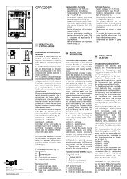
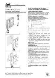
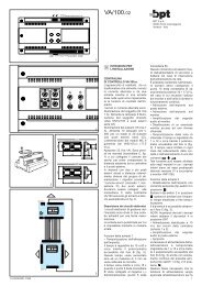
Funzione dei morsetti<br />
3÷11 e 20: morsetti per il collegamento<br />
del monitor standard <strong>VMF</strong>/<strong>200</strong><br />
3÷20: morsetti per il collegamento del<br />
monitor intercomunicante <strong>VMF</strong>/<strong>203</strong><br />
3 segnale video cavo<br />
4 schermo s. video coassiale<br />
Se la linea non prosegue collegare<br />
una resistenza da 75Ω (viola-verdenero-oro)<br />
tra i morsetti 3 e 4.<br />
3 s.video positivo doppino<br />
4 s.video negativo telefonico<br />
Se la linea non prosegue collegare<br />
una resistenza da 56Ω (verde-blunero-oro)<br />
tra i morsetti 3-5 e 4-5.<br />
5 – 14,5÷17,5V<br />
6 + alimentazione monitor<br />
7 ingresso chiamata dal posto<br />
esterno<br />
8 audio al monitor<br />
9 audio al posto esterno<br />
10 Aux - servizi ausiliari<br />
11 (24V 1A) ( 1 )<br />
12 ingresso chiamata dal derivato<br />
intercomunicante<br />
13 comune chiamata derivati intercomunicanti<br />
14 chiamata al derivato n. 1<br />
15 chiamata al derivato n. 2<br />
16 chiamata al derivato n. 3<br />
17 occupato<br />
18 luce scale ( 2 )<br />
19 autoinserimento<br />
20 ingresso chiamata dal pianerottolo<br />
( 1 ) Per ottenere questa funzione il<br />
commutatore SW4 (fig. 7-8) deve<br />
essere portato nella posizione<br />
comando ausiliario Aux • .<br />
( 2 ) Per ottenere questa funzione il<br />
commutatore SW4 (fig. 7-8) deve<br />
essere portato nella posizione luce<br />
scale .<br />
Caratteristiche tecniche<br />
• Cinescopio: 4” (10 cm).<br />
• Alimentazione: 14,5÷17,5Vcc.<br />
• Assorbimento: max. 400mA (8mA a<br />
riposo).<br />
• Banda passante a -3dB: 5MHz.<br />
1
• Ingresso video:1Vpp(da 0,7 a<br />
2Vpp) da linea coassiale; V+<br />
0,6Vpp, V– 0,6 Vpp (da 0,3 a<br />
0,9Vpp) da linea differenziale (doppino<br />
telefonico).<br />
• Impedenza d’ingresso video:<br />
≥22kΩ<br />
• Segnale di chiamata: bitonale per<br />
chiamate provenienti dal posto<br />
esterno (e chiamate dal pianerottolo)<br />
e a nota continua per chiamate<br />
interne (<strong>VMF</strong>/<strong>203</strong>).<br />
• Segreto di conversazione verso il<br />
posto esterno (<strong>VMF</strong>/<strong>203</strong>).<br />
• Temperatura di funzionamento: da 0<br />
°C a +35 °C.<br />
• Dimensioni: 195x230x72mm.<br />
Il fusibile F1 di protezione tipo T<br />
500mA è situato sul circuito stampato<br />
(fig. 7-8).<br />
(Fusibile: F = rapido, T = ritardato).<br />
NOTA. Effettuare i collegamenti all’apparecchio<br />
seguendo gli schemi di<br />
impianto realizzati con il monitor<br />
VM/<strong>200</strong> o VM/<strong>203</strong>.<br />
ATTENZIONE. Si raccomanda di<br />
installare il monitor in ambiente<br />
asciutto.<br />
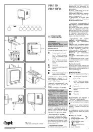
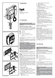
Istruzioni per l’installazione<br />
Spostare il dispositivo di bloccaggio<br />
come indicato in fig. 3. Sfilare il supporto<br />
in acciaio dal monitor e fissarlo<br />
ad un’altezza adatta all’utente<br />
mediante i tasselli e viti in dotazione.<br />
Rispettare l’indicazione ALTO e fare in<br />
modo che l’uscita dei cavi dalla parete<br />
coincida con l’apposito passaggio<br />
del supporto (fig. 4).<br />
Svitare le due viti di fissaggio e togliere<br />
la parte sinistra del mobile (fig. 5).<br />
Passare i conduttori attraverso la feritoia<br />
sul fondo del monitor, posizionare<br />
il monitor nel supporto da parete ed<br />
innestarlo al supporto stesso con un<br />
movimento verso il basso (fig. 6).<br />
Per evitare cadute del monitor a<br />
causa di urti accidentali, bloccare il<br />
monitor stesso al supporto da parete<br />
spostando verso destra il dispositivo<br />
di bloccaggio.<br />
Procedere nella maniera opposta in<br />
caso di smontaggio del monitor.<br />
Effettuare i collegamenti e rimettere la<br />
parte sinistra del mobile fissandola<br />
con le due viti.<br />
GB INSTALLATION<br />
INSTRUCTIONS<br />
WARNING FOR THE INSTALLER<br />
These instructions should be attached<br />
to the receiver.<br />
<strong>VMF</strong>/<strong>200</strong> FLAT MONITOR WITH<br />
HANDSET WALL MOUNTED VER-<br />
SION<br />
Monitor with video and secrecy of<br />
speech. With this monitor, the video<br />
signal may be transmitted by either a<br />
coaxial or a twisted pair.<br />
Can be converted in table-top version<br />
using the VKT/<strong>203</strong>F kit.<br />
<strong>VMF</strong>/<strong>200</strong>, figure 1, is equipped with<br />
the following controls:<br />
ON/OFF-brightness control<br />
(side thumbweel D) ( 1 )<br />
Entry panel activation ( 1 )<br />
•/ Auxiliary or stairs light control<br />
(can be selected using the<br />
SW4 switch, figure 7-8) ( 2 )<br />
NOTE. The monitor is supplied<br />
with SW4 switch in stair<br />
light position.<br />
Door release control ( 2 )<br />
(<br />
2<br />
1 ) The activation of the monitor and its<br />
subsequent connection to the external<br />
entry panel, are only possible if the<br />
system is not engaged by other conversations.<br />
( 2 ) The stairs light and door release<br />
controls may only be activated by the<br />
monitor when it is switched on.<br />
WARNINGS FOR THE USER<br />
- Please do not open or tamper the<br />
device (high voltage!).<br />
- Please avoid knocking or bumping<br />
the apparatus as it could result in<br />
the breakage of the picture tube and<br />
the consequent projection of glass<br />
fragments.<br />
- In the case of breakdown or modification<br />
of the apparatus of the<br />
system (such as power supplier ...)<br />
please contact a specialized maintenance<br />
service.<br />
Personal door-bell button<br />
The monitor is fitted with a differentiated<br />
call input (i.e.: for calls from landing<br />
and external entry panel) a twotone<br />
call, figure 9.<br />
<strong>VMF</strong>/<strong>203</strong> MONITOR WITH INTER-<br />
COM AND HANDSET WALL MOUN-<br />
TED VERSION<br />
This monitor has the same features<br />
and controls as the <strong>VMF</strong>/<strong>200</strong> model,<br />
but is also equipped with 3 buttons for<br />
communication with other intercom<br />
units, and a red LED which indicates<br />
when the line is busy, figure 2.<br />
The monitor permits to identify the<br />
source of a call: a continuous call tone<br />
identifies calls from other intercom<br />
units and a two-tone call identifies<br />
calls from the external entry panel (or<br />
from the landing).<br />
A call from the entry panel during an<br />
internal conversation between two<br />
intercom units is indicated by the activation<br />
of the monitor and the emission<br />
of a low acoustic signal.<br />
In this case, communication with the<br />
entry panel (and hence the possibility<br />
of activating both the door release<br />
control and the stairs light relay)<br />
may be established by hanging the<br />
handset of the intercom unit currently<br />
in use and lifting the handset of the<br />
one signalling a call.<br />
The monitor requires the use of<br />
VSE/<strong>200</strong>.01 selector.<br />
Entry panel selection in systems<br />
with several entrances<br />
If the system foresee more than one<br />
entry panel, set the SW/4 switch, figure<br />
7-8, to the stairs light position to<br />
select this option.<br />
The VSI/<strong>200</strong> selector allows you to<br />
select the external entry panel or camera<br />
from the monitor in sequential mode.<br />
To operate the selector: press the<br />
entry panel activation button to turnon<br />
the monitor; and then press the<br />
stair light control button to select the<br />
entry panels.<br />
NOTE. In the event a call is made from<br />
the entry panel, the selection in progress<br />
is interrupted.<br />
If the external call is addressed to the<br />
monitor making the selection, the<br />
monitor displays the image filmed at<br />
the external entry from where the call<br />
is addressed to another monitor, the<br />
image disappears from the monitor.<br />
Function of each terminal<br />
3÷11 and 20: terminals for connection<br />
of standard <strong>VMF</strong>/<strong>200</strong> monitor<br />
3÷20: terminals for connection of<br />
<strong>VMF</strong>/<strong>203</strong> monitor with intercom facility<br />
3 video signal coaxial<br />
4 video signal shield cable<br />
If the video line ends at this monitor,<br />
connect a 75Ω (violet-green-black-gold)<br />
resistor between terminals 3 and 4.<br />
3 pos. video signal twisted<br />
4 neg. video signal pair<br />
If the video line ends at this monitor,<br />
connect a 56Ω (green-blue-black-gold)<br />
resistor between terminals 3-5 and 4-5.<br />
5 – 14,5÷17,5V<br />
6 + supply voltage to monitor<br />
7 call input from entry panel<br />
8 audio to monitor<br />
9 audio to entry panel<br />
10 Aux - auxiliary services<br />
11 (24V 1A) ( 1 )<br />
12 call input from intercom receiver<br />
13 call common intercom receivers<br />
14 call to receiver no. 1<br />
15 call to receiver no. 2<br />
16 call to receiver no. 3<br />
17 engaged<br />
18 stairs light ( 2 )<br />
19 auto-switch on<br />
20 call input from landing<br />
( 1 ) This function is enabled by setting<br />
the SW4 switch, figure 7-8, to the auxiliary<br />
control position Aux • .<br />
( 2 ) This function is enabled by setting<br />
the SW4 switch, figure 7-8, to the stairs<br />
light position .<br />
Technical features<br />
• Picture screen: 4” (10 cm).<br />
• Supply voltage: 14,5÷17,5VDC<br />
• Current demand: 400mA max. (8mA<br />
quiescent).<br />
• Bandwidth response at -3dB: 5MHz.<br />
•Video input: 1Vpp (0,7 to 2Vpp) from<br />
coaxial line; + video signal 0,6Vpp, -<br />
video signal 0,6Vpp (0,3 to 0,9 Vpp)<br />
from differential line (twisted pair).<br />
•Video input impedance: ≥22kΩ.<br />
• Call signal: two-tone call signal at entry<br />
panel (and at personal door-bell button)<br />
and continuous tone call signal<br />
for internal calls (<strong>VMF</strong>/<strong>203</strong>).<br />
• Audio secrecy to entry panel<br />
(<strong>VMF</strong>/<strong>203</strong>).<br />
• Working temperature range: from 0 °C<br />
to +35 °C.<br />
• Dimensions: 195x230x72mm.<br />
The monitor is protected by the slow<br />
blow fuse F1 - T 500mA - located on<br />
monitor’s printed card, figures 7-8.<br />
(Fuse: F = fast, T = slow).<br />
NOTE. Connect wires to terminals in<br />
accordance to VM/<strong>200</strong> or VM/<strong>203</strong><br />
wiring diagrams.<br />
WARNING. It is recommended to<br />
install the monitor in a dry place.<br />
Installation instructions<br />
Slide the locking latch as shown in<br />
figure 3. Slide the steel frame out, and<br />
fix it on the wall at a suitable height by<br />
using the screws and retainers included<br />
in the pack.<br />
Please, pay attention to place the<br />
frame with the indication TOP in upper<br />
position, and make the hole, figure 4,<br />
to coincide with the cable junction<br />
box.<br />
Unscrew the two screws, figure 5, and<br />
take the left part of the housing out.<br />
Pass the cables through the slot at the<br />
bottom of the housing, place the monitor<br />
on the steel frame and fix it by sliding<br />
it downwards, figure 6.<br />
To avoid undesired falls of the monitor<br />
caused by accidental shocks, lock it<br />
by sliding the latch to the right.<br />
Proceed the opposite way to unmount<br />
the monitor. Make all the connections<br />
and fix the cover of the left part of the<br />
housing with the two screws.<br />
D INSTALLATIONS-<br />
ANLEITUNG<br />
ACHTUNG!<br />
NUR FÜR INSTALLATEUR<br />
Diese Anleitungen müßen jede der<br />
Sprechstelle begleiten.<br />
FLACHMONITOR MIT HÖRER<br />
<strong>VMF</strong>/<strong>200</strong> WANDAUSFÜHRUNG<br />
Monitor Mitseh- und Mithörgesperrt<br />
für den Videosignalempfang über<br />
Koaxial- oder Telefonkabel.<br />
Kann mit dem entsprechenden<br />
Montage Kit VKT/<strong>203</strong>F auch als<br />
Tischausführung verwendet werden.<br />
Mit folgenden Schaltelementen (Abb. 1):<br />
EIN/AUS, Helligkeit (seitlich<br />
angeordnete Knopf D) ( 1 ).<br />
Außenstationeneinschaltung ( 1 )<br />
•/ Zusatzsteuerung oder Treppenlicht<br />
(mittels Umschalter<br />
SW4 wählbar, Abb. 7-8)( 2 )<br />
ANMERKUNG. Der monitor ist<br />
mit Unschalter SW4 auf<br />
Treppenlicht Position geliefert.<br />
Türöffnertaste ( 2 )<br />
( 1 ) Die Einschaltung des Gerätes und<br />
der anschließende Anschluß an die<br />
Außenstation sind nur möglich, wenn<br />
die Anlage nicht besetzt ist.<br />
( 2 ) Treppenlicht und Türöffner sind nur<br />
bei eingeschaltetem Monitor schaltbar<br />
HINWEISE FÜR DEN NUTZER<br />
- Bitte Gerät nicht öffnen oder aufbrechen<br />
(hohe Spannung!).<br />
- Zur Vermeidung eines Bildröhrenbruchs,<br />
Stösse und Schläge unterlassen.<br />
- Bei Störungen, Änderungen oder<br />
Reparaturen an den Geräten (Netzgerät,<br />
usw.) nur an Spezialisten<br />
wenden.<br />
Etagenanruf<br />
Das Gerät verfügt über einen Eingang<br />
für die Anruf unterscheidung (z.B.<br />
Etagenanruf) mit Zweiklangton (Abb.<br />
9).<br />
INTERCOM-FLACHMONITOR<br />
MIT HÖRER <strong>VMF</strong>/<strong>203</strong><br />
WANDAUSFÜHRUNG<br />
Eigenschaften und Bedienelemente<br />
wie <strong>VMF</strong>/<strong>200</strong>, jedoch zusätzlich mit 3<br />
Tasten für den Anruf anderer<br />
Innensprechstellen und einen roten<br />
LED für die Besetztanzeige (Abb. 2).<br />
Das Gerät macht die Herkunft des<br />
Anrufes erkennbar durch Dauerton<br />
für Anrufe von anderen Intercom-<br />
Stellen und Zweiklangton für Anrufe<br />
von der Außenstation (oder von der<br />
Etage).<br />
Ein Anruf von der Außenstation während<br />
eines Gespräches zwischen<br />
Innensprechstellen wird durch die<br />
Einschaltung des Monitors sowie<br />
eines schwachen Tonsignals im Hörer<br />
angezeigt.<br />
In diesem Fall kann das Gespräch mit<br />
der Außenstation (und damit die<br />
Betätigung des Türöffners und des<br />
Treppenlichtes) durch Auflegen der<br />
Hörer und Abheben des Hörers an<br />
der angerufenen Innensprechstelle<br />
aufgenommen werden.<br />
Der monitor benötigt den Gebrauch<br />
des Wählers VSE/<strong>200</strong>.01.<br />
Auswahl der Außenstation bei<br />
Anlagen mit mehreren Eingängen<br />
Sollte die Anlage mehr als eine<br />
Außenstelle vorsehen und diese<br />
gewählt werden, ist der Umschalter<br />
SW/4 (Abb. 7-8) auf Position Treppenlicht<br />
zu stellen.<br />
Der Wahlschalter VSI/<strong>200</strong> ermöglicht<br />
die Auswahl der Außenstation oder<br />
des Aufnahmegeräts über den<br />
Bildschirm auf sequentielle Weise.<br />
Um diese Betriebsart einzuschalten,<br />
die Taste Einschalten Außenstation<br />
betätigen, um den Monitor einzuschalten,<br />
und danach die Taste<br />
Treppenbeleuchtung zwecks Auswahl<br />
der Außenstationen.<br />
HINWEIS. Ein eventuell von der<br />
Außenstation kommender Ruf unterbricht<br />
den Auswahlvorgang und, falls<br />
der Ruf für die gleiche interne<br />
Nebenstelle bestimmt ist, erscheint<br />
auf dem Bildschirm das Bild, das an<br />
der Außenstation aufgenommen<br />
wurde, von der aus der Ruf erfolgt ist.<br />
Sollte der Ruf dagegen für eine andere<br />
interne Nebenstelle bestimmt sein,<br />
so verschwindet das Bild vom<br />
Bildschirm.<br />
Belegung der Klemmleiste<br />
3÷11 und 20: Klemmen für den<br />
Anschluß des Standardmonitors<br />
<strong>VMF</strong>/<strong>200</strong><br />
3÷20: Klemmen für den Anschluß des<br />
Intercom-Monitors <strong>VMF</strong>/<strong>203</strong>
3 Videosignal Koaxial-<br />
4 Videosignalabsch. Kabel<br />
Am ende der Linie ist ein Widerstand<br />
von 75Ω (violet-grün-schwarz-gold)<br />
zwischen den Klemmen 3 und 4 einzusetzen.<br />
3 Videosignal Positiv Telefon-<br />
4 Videosignal Negativ Kabel<br />
Am ende der Linie ist ein Widerstand<br />
von 56Ω (grün-blau-schwarz-gold)<br />
zwischen den Klemmen 3-5 und 4-5<br />
einzusetzen.<br />
5 – 14,5 ÷ 17,5V<br />
6 + Monitorversorgung<br />
7 Anrufeingänge zu der Außenstation<br />
8 Ton zum Monitor<br />
9 Ton zur Außenstation<br />
10 Aux - Zusatzservices<br />
11 (24V 1A) ( 1 )<br />
12 Anrufeingänge von Intercom-<br />
Sprechgarnitur<br />
13 Intercom-Sprechgarnituren gemeinsamer<br />
Anruf<br />
14 Anruf zu der Sprechgarnitur Nr. 1<br />
15 Anruf zu der Sprechgarnitur Nr. 2<br />
16 Anruf zu der Sprechgarnitur Nr. 3<br />
17 Besetzanzeige<br />
18 Treppenlicht ( 2 )<br />
19 Autoeinschaltung<br />
20 Anrufeingänge von Etagen<br />
( 1 ) Für diese Funktion ist der<br />
Umschalter SW4 (Abb. 7-8) auf<br />
Position Zusatzsteuerung Aux. • .<br />
( 2 ) Für diese Funktion ist der<br />
Umschalter SW4 (Abb.7-8) auf<br />
Position Treppenlicht zu stellen.<br />
Technische Daten<br />
•Bildröhre: 4-Zoll (10 cm).<br />
• Stromversorgung: 14,5÷17,5VDC.<br />
• Stromaufnahme: 400mA max. (8mA<br />
Ruhestrom).<br />
• Durchlaßbereich bei -3dB: 5MHz.<br />
•Videoeingang:1Vss (0,7 bis 2Vss)<br />
von Koaxialkabel; V + 0,6Vss, V-<br />
0,6ss (0,3 bis 0,9Vss) von Differentialleitung<br />
(Telefon-Kabel).<br />
•Video-Eingangsimpedanz: ≥22kΩ<br />
• Rufsignal: Zweitonsignal mit Lautstärkeregelung<br />
von der Außenstation<br />
und der Etage und Dauertonsignal<br />
von Innensprechstellen<br />
(<strong>VMF</strong>/<strong>203</strong>).<br />
• Mithörsperre zur Außenstation<br />
(<strong>VMF</strong>/<strong>203</strong>).<br />
• Betriebstemperatur: von 0 °C bis<br />
+35 °C.<br />
• Abmessungen: 195x230x72mm.<br />
Der Monitor wird durch die Sicherung<br />
F1 - T 500mA - angebracht auf der<br />
Monitorplatine, geschütz (Abb. 7-8).<br />
(Sicherung: F = flink, T = träge).<br />
HINWEIS. Die Anschlüsse am Gerät<br />
nach den Schaltbildern von Monitor<br />
VM/<strong>200</strong> oder VM/<strong>203</strong> vornehmen.<br />
ACHTUNG. Es wird empfohlen den<br />
Monitor an einer geschützten Stelle<br />
zu installieren.<br />
Installationsanweisung<br />
Verriegelung erfolgt gemäß<br />
Darstellung Abb. 3, Stahlrahmen vom<br />
Monitor entfernen und unter<br />
Beachtung der Oberseite an der<br />
Wand, auf eine angemessene Höhe,<br />
anbringen. Unter Verwendung der<br />
beigefügten Dübel und Schrauben<br />
montieren, Kabel durch Öffnung führen<br />
(Abb. 4).<br />
Zwei Befestigungschrauben lösen<br />
und Hörergabel entfernen (Abb. 5).<br />
Kabeldurchbrücke für Kabeldurchführung<br />
entfernen und Kabel einziehen<br />
(Abb. 6).<br />
Monitor auf Halterung aufsetzen und<br />
Verriegelung nach rechts schieben<br />
um eine Beschädigung des unbefestigten<br />
Monitors zu vermeiden.<br />
Anschlüsse verbinden, Hörer und<br />
Hörergabel anbringen und mit zwei<br />
Schrauben befestigen.<br />
F INSTRUCTIONS<br />
POUR L’INSTALLATION<br />
PRECAUTIONS<br />
POUR L’INSTALLATEUR<br />
Cettes instructions doivent accompagner<br />
chaque poste intérieur.<br />
RECEPTEUR VIDEO<br />
MURAL PLAT<br />
AVEC COMBINE <strong>VMF</strong>/<strong>200</strong><br />
Récepteur vidéo avec secret vidéo et<br />
de conversation convenant pour la<br />
réception du signal vidéo transmis<br />
soit par câble coaxial, soit par paire<br />
torsadé.<br />
L’appareil, associé au kit VKT/<strong>203</strong>F,<br />
peut être utilisé en version de table.<br />
Il est muni des commandes suivantes<br />
(fig. 1):<br />
Marche/arrêt-réglage de la luminosité<br />
(commande D) ( 1 )<br />
Mise en marche du poste extérieur<br />
( 1 )<br />
•/ Commande auxiliaire ou de<br />
minuterie (sélectionnable à<br />
l’aide du sélecteur SW4, fig. 7-<br />
8) ( 2 )<br />
NOTE. Le moniteur est fourni<br />
avec le sélecteur SW4 en<br />
position minuterie.<br />
Commande ouvre-porte (gâcheélectrique)<br />
( 2 )<br />
( 1 ) La mise sous tension de l’appareil<br />
et, en conséquence, sa connexion<br />
avec le poste extérieur seront possibles<br />
uniquement si l’installation n’est<br />
pas occupée par d’autres communications.<br />
( 2 ) On peut transmettre, à partir du<br />
récepteur vidéo, les commandes de<br />
minuterie et de gâche uniquement<br />
avec l’appareil sous tension.<br />
PRECAUTIONS POUR L’USAGER<br />
- Ne pas ouvrir l’appareil; attention<br />
haute tension!<br />
- Eviter les chocs qui pourraient<br />
provoquer l’implosion du tube<br />
cathodique et la projection de fragments<br />
de verre.<br />
- En cas de défaut, de modification<br />
ou d’intervention sur les appareils<br />
de l’installation (alimentation, etc.),<br />
s’addresser exclusivement au personnel<br />
spécialisé.<br />
Appel porte palière<br />
L’appareil est muni d’une entrée pour<br />
appel différencié (par exemple à partir<br />
de l’étage) a note bitonale (fig. 9).<br />
RECEPTEUR VIDEO MURAL<br />
PLAT A INTERCOMMUNICATION<br />
AVEC COMBINE <strong>VMF</strong>/<strong>203</strong><br />
En plus des caractéristiques et des<br />
commandes du mod. <strong>VMF</strong>/<strong>200</strong>, l’appareil<br />
est équipé de 3 boutons-poussoir<br />
pour appeler les autres appareils<br />
et d’une LED rouge qui signale la<br />
ligne occupée (fig. 2).<br />
L’appareil permet d’identifier la provenance<br />
de l’appel: note continue pour<br />
des appels à partir d’appareils à<br />
intercommunication et note bitonale<br />
pour des appels provenant du poste<br />
extérieur (ou de l’étage).<br />
Un appel à partir du poste extérieur<br />
durant une conversation entre des<br />
postes intérieurs est signalée aussi<br />
bien par l’allumage du récepteur<br />
vidéo que par un faible signal audio<br />
dans l’écouteur.<br />
Dans ce cas la communication avec<br />
le poste extérieur (et donc la possibilité<br />
d’activer aussi bien la gâche<br />
que le relais d’éclairage dans les<br />
escaliers) peut être établie en raccrochant<br />
les récepteurs et en soulevant<br />
celui de l’appareil appelé.<br />
Avec cet moniteur doit être installé le<br />
sélecteur VSE/<strong>200</strong>.01.<br />
Selection du poste extérieur dans<br />
des installations ayant plusieurs<br />
entrées<br />
Si l’istallation prévoit plus d’un poste<br />
extérieur et qu’on désire le sélectionner,<br />
mêtre le sélecteur SW/4 (fig. 7-8)<br />
sur la position minuterie .<br />
Le sélecteur VSI/<strong>200</strong> permet la sélection<br />
du poste extérieur ou de l’unité<br />
de prise de vue à partir du récepteur<br />
vidéo de manière séquentielle.<br />
Pour obtenir ce type de fonctionnement<br />
presser le bouton-poussoir<br />
insertion poste externe pour l’allumage<br />
du récepteur vidéo, puis le<br />
bouton-poussoir minuterie pour la<br />
sélection des postes exterieurs.<br />
NOTE. Un appel éventuel à partir du<br />
poste extérieur interrompt la sélection<br />
en cours et, si l’appel s’adresse au<br />
même poste intérieur, l’image reprise<br />
du poste extérieur d’où a été effectué<br />
l’appel apparaît sur le récepteur vidéo.<br />
Si l’appel s’adresse à un autre poste<br />
intérieur, l’image disparaît du récepteur<br />
vidéo.<br />
Fonction des bornes<br />
3÷11 et 20: bornes pour la connexion<br />
du récepteur vidéo standard VM/<strong>200</strong>.<br />
3÷20: bornes pour la connexion du<br />
récepteur vidéo à intercommunication<br />
VM/<strong>203</strong>.<br />
3 signal vidéo câble<br />
4 blindage s. vidéo coaxial<br />
Si la ligne ne continue pas, connecter<br />
une résistance de 75Ω (violet-vertnoir-or)<br />
entre les bornes 3 et 4.<br />
3 s.vidéo positif paire<br />
4 s.vidéo negatif torsadé<br />
Si la ligne ne continue pas, connecter<br />
une résistance de 56Ω (vert-bleu-noiror)<br />
entre les bornes 3-5 et 4-5.<br />
5 – 14,5÷17,5V alimentation<br />
6 + récepteur vidéo<br />
7 entrée appel depuis le poste<br />
extérieur<br />
8 audio au récepteur vidéo<br />
9 audio au poste extérieur<br />
10 Aux - commandes auxiliaires<br />
11 (24V 1A) ( 1 )<br />
12 entrée appel depuis le poste<br />
intérieur à intercommunication<br />
13 commun appel postes intérieurs<br />
à intercommunication<br />
14 appel vers le poste intérieur n. 1<br />
15 appel vers le poste intérieur n. 2<br />
16 appel vers le poste intérieur n. 3<br />
17 occupé<br />
18 minuterie ( 2 )<br />
19 auto-branchement<br />
20 entrée appel depuis la porte<br />
palière<br />
( 1 ) Pour obtenir cette fonction le sélecteur<br />
SW4 (fig. 7-8) doit être positionné<br />
sur commande auxiliaire Aux • .<br />
( 2 ) Pour obtenir cette fonction le sélecteur<br />
SW4 (fig. 7-8) doit être positionné<br />
sur minuterie .<br />
Caractéristiques techniques<br />
•Tube: 4” (10 cm).<br />
• Alimentation: 14,5÷17,5Vcc.<br />
• Consommation: 400mA maxi (8mA<br />
à repos).<br />
• Bande passante à -3dB: 5MHz.<br />
• Entrée vidéo:1Vpp (de 0,7 à 2Vpp)<br />
provenant de la ligne coaxiale; V+<br />
0,6Vpp, V– 0,6Vpp (de 0,3 à 0,9<br />
Vpp) provenant de la ligne differentielle<br />
(paire torsadé).<br />
• Impédance d’entrée video: ≥22kΩ<br />
• Signal d’appel: bitonal à partir du<br />
poste extérieur (et de l’étage) et a<br />
note continue pour les appels internes<br />
(<strong>VMF</strong>/<strong>203</strong>).<br />
• Secret de conversation vers le<br />
poste extérieur (<strong>VMF</strong>/<strong>203</strong>).<br />
• Température de fonctionnement: de<br />
0 °C à +35 °C.<br />
• Dimensions: 195x230x72mm.<br />
Le fusible F1 de protection du type T<br />
500mA est placé sur le circuit<br />
imprimé (fig. 7-8).<br />
(Fusible: F = rapide, T = retardé).<br />
NOTE. Effectuer les branchements à<br />
l’appareil en suivant les schémas d’installation<br />
réalisés avec le récepteur<br />
VM/<strong>200</strong> ou VM/<strong>203</strong>.<br />
ATTENTION. Le moniteur doit être<br />
installé dans une pièce séche.<br />
Instructions d’installation<br />
Dégager le dispositif de verrouillage<br />
comme indiqué à la fig. 3, ôter de<br />
l’appareil le support mural en acier et<br />
le fixer à un’hauteur apte pour l’utilisateur,<br />
à l’aide des quatre vis fournies.<br />
Il est impératif que l’indication HAUT<br />
soit respectée et que la sortie des<br />
câbles du mur soit en coincidence<br />
avec le passage correspondant du<br />
support comme indiqué à la fig. 4.<br />
Dévisser les deux vis de fixation et<br />
ôter la partie gauche de l’appareil<br />
(fig. 5).<br />
Passer les conducteurs à travers l’ouverture<br />
située au fond du récepteur,<br />
loger le récepteur à son support<br />
mural et l’enclipser en le glissant vers<br />
le bas (fig. 6).<br />
Bloquer l’appareil à son support en<br />
déplaçant ver le droite l’élément de<br />
verrouillage afin d’éviter tout risque<br />
de chute accidentelle.<br />
Procéder de la façon inverse pour le<br />
démontage du récepteur. Après avoir<br />
effectué les connexions remonter la<br />
partie gauche et la fixer à l’aide de<br />
ses deux vis.<br />
E INSTRUCCIONES<br />
PARA LA INSTALACION<br />
ADVERTENCIA AL INSTALADOR<br />
Estas instrucciones se deben<br />
anexar al derivado interno.<br />
MONITOR PLANO DE PARED<br />
CON AURICOLAR <strong>VMF</strong>/<strong>200</strong><br />
Monitor con secreto de vídeo y de<br />
conversación, idóneo para la recepción<br />
de la señal de vídeo transmitida<br />
por medio de cable coaxial o par<br />
telefónico.<br />
El monitor se puede utilizar en la version<br />
de sobremesa en combinación<br />
con el kit VKT/<strong>203</strong>F.<br />
El aparato está dotado de los siguientes<br />
mandos (fig. 1):<br />
Encendido/apagado-luminosidad<br />
(mando D) ( 1 )<br />
Habilitación placa exterior ( 1 )<br />
•/ Mando auxiliar o luz de la escalera<br />
(se selecciona a través del<br />
conmutador SW4, fig. 7-8) ( 2 )<br />
NOTA. El monitor se provee con<br />
el conmutador SW4 en la posición<br />
luz de la escalera.<br />
Abrepuerta ( 2 )<br />
( 1 ) El encendido del aparato y la consiguiente<br />
conexión con la placa exterior<br />
se pueden realizar solo si el equipo<br />
no está ocupado por otras comunicaciones.<br />
( 2 ) Los mandos luz de la escalera y<br />
abrepuerta se pueden accionar desde<br />
el monitor solo con el aparato encendido.<br />
ADVERTENCIAS<br />
PARA EL USUARIO<br />
- No abrir ni manipular el aparato:<br />
en el interior hay alta tension.<br />
- Evitar choques y golpes al aparato<br />
que puedan causar la implosión<br />
del tubo catódico y proyección de<br />
fragmentos de vidrio.<br />
- En caso de avería o necesidad de<br />
modificación o intervención sobre<br />
los aparatos de la instalación (alimentador,<br />
etc.) dirigirse al personal<br />
especializado.<br />
Llamada desde el rellano<br />
El monitor está provisto de una entrada<br />
para llamada diferenciada (ej.<br />
desde el rellano) a nota bitonal (fig. 9).<br />
3
MONITOR PLANO<br />
INTERCOMUNICANTE DE PARED<br />
CON AURICULAR <strong>VMF</strong>/<strong>203</strong><br />
Además de las características y de<br />
los mandos del monitor <strong>VMF</strong>/<strong>200</strong>, el<br />
aparato está dotado de tres pulsadores<br />
para la llamada a los demás aparatos<br />
y de un diodo luminoso rojo<br />
(LED) para la señalización de linea<br />
ocupada (fig. 2).<br />
El monitor permite identificar la proveniencia<br />
de la llamada: nota continua<br />
para aquellas desde aparatos intercomunicantes<br />
y notas bitonales para<br />
las que provienen de la placa exterior<br />
(o desde el rellano).<br />
Una llamada desde la placa exterior<br />
durante una conversación entre derivados<br />
internos se señala mediante el<br />
encendido del monitor y por una leve<br />
señal de audio en el auricular.<br />
En este caso, la comunicación con la<br />
placa exterior (y, por tanto, la posibilidad<br />
de accionar el abrepuerta o el<br />
relé de la luz de la escalera) podrá<br />
establecerse colgando los auriculares<br />
y levantando nuevemente el del<br />
aparato llamado.<br />
Con este monitor debe ser instalado<br />
el selector VSE/<strong>200</strong>.01.<br />
Selección de la placa exterior<br />
en equipos con varias entradas<br />
Cuando la instalación prevea más de<br />
una placa exterior y se desee la<br />
selección de la misma, colocar el<br />
conmutador SW/4 (fig. 7-8) en la<br />
posición de luz escalera .<br />
El selector VSI/<strong>200</strong> permite seleccionar<br />
la placa exterior o la unidad de<br />
captación desde los monitores en<br />
modo secuencial.<br />
Para obtener este tipo de funcionamiento,<br />
pulsar primero el botón de<br />
activación de la placa exterior para<br />
encender el monitor, y luego el de luz<br />
de la escalera para la selección de<br />
las placas exteriores.<br />
NOTA. Una eventual llamada desde la<br />
placa exterior interrumpe la selección<br />
en curso y, si está dirigida al mismo<br />
derivado interno, en el monitor aparece<br />
la imagen captada en la placa exterior<br />
desde el cual proviene.<br />
Si la llamada está dirigida a otro derivado<br />
interno, en el monitor desaparece<br />
la imagen<br />
Funciones de los bornes<br />
3÷11 y 20: bornes para la conexión<br />
del monitor estándar <strong>VMF</strong>/<strong>200</strong><br />
3÷20: bornes para la conexión del<br />
monitor intercomunicante <strong>VMF</strong>/<strong>203</strong><br />
3 señal de vídeo cable<br />
4 pantalla s. de vídeo coaxial<br />
Si la linea no continúa conectar una<br />
resistencia de 75Ω (violeta-verdenegro-oro)<br />
entre los bornes 3 y 4.<br />
3 s. de vídeo pos. cable<br />
4 s. de vídeo neg. telefónico<br />
Si la linea no continúa conectar una<br />
resistencia de 56Ω (verde-azul-negrooro)<br />
entre los bornes 3-5 y 4-5.<br />
5 – 14,5 ÷ 17,5V<br />
6 + alimentación monitor<br />
7 entrada de la llamada desde la<br />
placa exterior<br />
8 audio al monitor<br />
9 audio a la placa exterior<br />
10 Aux - servicios auxiliares<br />
11 (24V 1A) ( 1 )<br />
12 entrada de la llamada desde al<br />
derivado intercomunicante<br />
13 llamada común derivados intercomunicantes<br />
14 llamada al derivado n. 1<br />
15 llamada al derivado n. 2<br />
16 llamada al derivado n. 3<br />
17 ocupado<br />
18 luz de la escalera ( 2 )<br />
19 activación automática<br />
20 entrada de la llamada desde el<br />
rellano<br />
( 1 ) Para obtener esta función, el conmutador<br />
SW4 (fig. 7-8) tendrá que colocarse<br />
en la posición de mando auxiliar<br />
Aux • .<br />
( 2 ) Para obtener esta función, el conmutador<br />
SW4 (fig. 7-8) tendrá que colocarse<br />
en la posición de luz escalera .<br />
4<br />
Características técnicas<br />
• Cinescopio: 4” (10 cm).<br />
• Alimentación: 14,5÷17,5Vcc.<br />
• Consumo: max. 400mA (8mA en<br />
reposo).<br />
• Banda pasante a -3dB: 5MHz.<br />
• Entrada vídeo: 1Vpp (de 0,7 a<br />
2Vpp). de linea coaxial; V+ 0,6Vpp,<br />
V– 0,6 Vpp (de 0,3 a 0,9Vpp) de<br />
linea diferencial (par telefónico).<br />
• Impedancia de entrada vídeo: ≥22<br />
kΩ.<br />
• Señal de llamada: bitonal para llamadas<br />
provenientes de la placa<br />
exterior (y desde el rellano) y de<br />
nota continua para llamadas internas<br />
(<strong>VMF</strong>/<strong>203</strong>).<br />
• Secreto de conversación hacia la<br />
placa exterior (<strong>VMF</strong>/<strong>203</strong>).<br />
•Temperatura de funcionamiento: 0<br />
°C a +35 °C.<br />
• Dimensiones: 195x230x72mm.<br />
El fusible F1 de protección tipo T<br />
500mA está ubicado en el circuito<br />
impreso (fig. 7-8).<br />
(Fusible F = rápido, T = retardado).<br />
NOTA. Efectuar las conexiones al aparato<br />
según a los esquemas de instalación<br />
realizados para el monitor<br />
VM/<strong>200</strong> o VM/<strong>203</strong>.<br />
ATENCION. Se recomienda instalar<br />
el monitor en un ambiente seco.<br />
Instrucciones para la instalación<br />
Desplazar el dispositivo de bloqueo<br />
como se indica en la fig. 3. Extraer el<br />
soporte de acero del monitor y fijarlo,<br />
a una altura tal que resulte apta para<br />
el usuario, mediante los tacos y tornillos<br />
que se entregan de serie.<br />
Colocar hacia arriba el extremo que<br />
lleva la indicación ALTO y hacer que<br />
la salida de los cables de la pared<br />
coincida con el orificio del soporte<br />
(fig. 4). Aflojar los dos tornillos de fijación<br />
y quitar la parte izquierda del<br />
mueble (fig. 5).<br />
Pasar los conductores a través de la<br />
ranura practicada en el fondo del<br />
monitor, colocar este último en el<br />
soporte de pared y encajarlo en el<br />
mismo con un movimiento hacia<br />
abajo (fig. 6).<br />
A los fines de evitar que el monitor se<br />
caiga a causa de un golpe accidental,<br />
asegurarlo al soporte de pared<br />
desaplazando hacia la derecha el<br />
dispositivo de bloqueo.<br />
Para desmontar el monitor, proceder<br />
la manera inversa.<br />
Realizar las conexiones, volver a<br />
montar la parte izquierda del mueble<br />
y fijarla con los dos tornillos.<br />
P<br />
INSTRUÇÕES PARA<br />
A INSTALAÇÃO<br />
AVISO PARA O INSTALADOR<br />
Estas instruções devem acompanhar<br />
cada derivado interno.<br />
MONITOR PLANO COM<br />
AUSCULTADOR <strong>VMF</strong>/<strong>200</strong><br />
Monitor com segredo vídeo e audio<br />
adequado para receber sinal vídeo<br />
transmitido quer por cabo coaxial<br />
quer por par telefónico.<br />
Pode ser utilizado na versão de mesa<br />
unido ao suporte VKT/<strong>203</strong>F.<br />
Possui os seguintes comandos (fig. 1):<br />
Ligado/desligado-luminosidade<br />
(comando D) ( 1 )<br />
Inserção da placa botoneira ( 1 )<br />
•/ Comando auxiliar ou luz das<br />
escadas (seleccionável através<br />
de comutador SW4, fig. 7-8) ( 2 )<br />
NOTA. O monitor é fornecido<br />
com o comutador SW4 na<br />
posição .<br />
Abertura da porta ( 2 )<br />
( 1 ) O acender do aparelho com ligação<br />
sucessiva com a placa botoneira é<br />
possível só se o equipamento não<br />
está ocupado com outras chamadas.<br />
( 2 ) É possível efectuar do monitor os<br />
comandos luz das escadas e abertura<br />
da porta só com o aparelho ligado.<br />
AVISO PARA O UTENTE<br />
- Não abrir ou manipular o aparelho:<br />
ao interno existe alta tensão.<br />
- Evitar embates ou pancadas ao<br />
aparelho que poderiam provocar a<br />
ruptura do tubo catódico com a<br />
consequente projecção dos fragmentos<br />
de vidro.<br />
- No caso de avaria, modificação ou<br />
intervenção nos aparelhos da<br />
instalação (alimentador, etc. ) deve<br />
ser contactado pessoal especializado.<br />
Chamada do patamar<br />
O aparelho possui uma entrada para<br />
chamada diferenciada (ex. do patamar)<br />
de nota de dois tons.<br />
MONITOR PLANO<br />
INTERCOMUNICANTE COM<br />
AUSCULTADOR <strong>VMF</strong>/<strong>203</strong><br />
Para lá das características e dos<br />
comandos do monitor <strong>VMF</strong>/<strong>200</strong>, o<br />
aparelho está dotado de três botões<br />
para a chamada aos outros aparelhos<br />
e de um LED vermelho para a<br />
sinalização de linha ocupada (fig. 2).<br />
O aparelho permite identificar a procedência<br />
da chamada: nota contínua<br />
para chamadas de aparelhos intercomunicantes<br />
e nota de dois tons para<br />
chamada procedente da placa botoneira<br />
(ou do patamar).<br />
Uma chamada da placa botoneira<br />
durante uma conversação interna é<br />
assinalada quer pela ligação do<br />
monitor quer por um sinal audio fraco<br />
no auscultador.<br />
Neste caso a comunicação com a<br />
placa botoneira (e, portanto, a possibilidade<br />
de accionar quer a abertura<br />
da porta quer o relé da luz das escadas)<br />
pode ser restabelecida pousando<br />
os auscultadores e voltando a<br />
levantar o do aparelho chamado.<br />
O monitor requer a utilização do<br />
selector VSE/<strong>200</strong>.01.<br />
Seleção da placa botoneira em<br />
instalações com mais entradas<br />
Se a instalação prevé mais que uma<br />
placa botoneira e pretende-se a<br />
selecção da mesma, o comutador<br />
SW4 (fig. 7-8) deve estar na posição<br />
luz das escadas .<br />
O selector VSI/<strong>200</strong> permite a<br />
selecção da placa botoneira ou da<br />
telecâmara do monitor de maneira<br />
sequencial.<br />
Para obter este tipo ce funcionamento<br />
carregar no botão inserção placa<br />
botoneira para a ligação do monitor<br />
e, em seguida, o botão Iuz escadas<br />
para a selecção das placas botoneiras.<br />
NOTA. Uma eventual chamada da<br />
placa botoneira interrompe a selecção<br />
em curso e, se a chamada e dirigida<br />
para o mesmo posto, no monitor aparece<br />
a imagem da placa botoneira de<br />
onde foi efectuada a chamada. Se a<br />
chamada é dirigida para outro posto a<br />
imagem desaparece no monitor.<br />
Função dos bornes<br />
3÷11 e 20: bornes para ligação do<br />
monitor <strong>VMF</strong>/<strong>200</strong><br />
3÷20: bornes para ligação do monitor<br />
<strong>VMF</strong>/<strong>203</strong><br />
3 sinal vídeo cabo<br />
4 massa sinal vídeo coaxial<br />
Se a linha coxial não avança, ligar<br />
uma resistência de 75Ω (roxo, verde,<br />
preto, ouro) entre os bornes 3 e 4.<br />
3 sinal vídeo positivo par<br />
4 sinal vídeo negativo telefónico<br />
Se a linha não avança, ligar uma resistência<br />
de 56Ω (verde, azul, preto,<br />
ouro) entre os bornes 3-5 e 4-5.<br />
5 – 14,5÷17,5V<br />
6 + alimentação monitor<br />
7 entrada chamada da placa botoneira<br />
8 audio para o monitor<br />
9 audio para a placa botoneira<br />
10 Aux 1 - serviços auxiliares<br />
11 (24V 1 A) ( 1 )<br />
12 entrada chamada do posto intercomunicante<br />
13 comum chamada posto intercomunicantes<br />
14 chamada para o posto n. 1<br />
15 chamada para o posto n. 2<br />
16 chamada para o posto n. 3<br />
17 ocupado<br />
18 luz das escadas<br />
19 auto-inserção<br />
20 entrada chamada do patamar<br />
( 1 ) Para obter esta função o comutador<br />
SW4 (fig. 7-8) deve ser posto na<br />
posição comando auxiliar Aux • .<br />
( 2 ) Para obter esta função o comutador<br />
SW4 (fig. 7-8) deve ser posto na<br />
posição luz escadas .<br />
Características técnicas<br />
• Cinescópio: 4" (10 cm).<br />
• Alimentação: 14,5÷17,5Vcc.<br />
• Consumo: 400mA máx. (8mA em<br />
descanso).<br />
• Banda passante a -3 dB: 5MHz.<br />
• Entrada vídeo: 1 Vpp (de 0,7 a<br />
2Vpp) de linha coaxial; V+ 0,6Vpp,<br />
V– 0,6Vpp (de 0,3 a 0,9Vpp) de<br />
linha diferencial (par telefónico).<br />
• lmpedância de entrada vídeo: ≥22<br />
kΩ.<br />
• Sinal de chamada: de dois tons<br />
para as chamadas procedentes da<br />
placa botoneira (e chamadas do<br />
patamar) e de nota continua para<br />
chamadas internas (<strong>VMF</strong>/<strong>203</strong>).<br />
• Segredo audio para a placa botoneira<br />
(<strong>VMF</strong>/<strong>203</strong>).<br />
• Temperatura de funcionamento: de<br />
0 °C a +35 °C.<br />
• Dimensões: 195 x 230 x 72 mm.<br />
O fusivel F1 de protecção tipo T<br />
500mA e situado no circuito impresso<br />
(fig. 7-8).<br />
Fusivel: f = rápido, T = retardado.<br />
NOTA. Efectuar as ligações ao aparelho<br />
seguindo os esquemas de instalação<br />
realizados com o monitor<br />
VM/<strong>200</strong> ou VM/<strong>203</strong>.<br />
ATENÇÃO. Se aconselha de instalar<br />
o monitor em ambiente enxuto.<br />
Instruções para a instalação<br />
Deslocar o dispositivo de bloqueamento<br />
como é indicado na fig. 3.<br />
Tirar o suporte em aço do monitor e<br />
fixá-lo a uma altura adequada ao<br />
utente através de calços e parafusos<br />
fornecidos. Respeitar a indicação<br />
ALTO e fazer de maneira que a saída<br />
dos cabos da parede coincida com a<br />
passagem própria do suporte (fig. 4).<br />
Desaparafusar os dois parafusos de<br />
fixação e tirar a parte esquerda do<br />
aparelho (fig. 5).<br />
Passar os condutores através da<br />
abertura no fundo do monitor, posicionar<br />
o monitor no suporte de parede<br />
e juntá-lo ao próprio suporte com<br />
um movimento para baixo (fig. 6).<br />
Para evitar quedas do monitor por<br />
causa de choques acidentais, bloquear<br />
o próprio monitor ao suporte<br />
de parede deslocando para direita o<br />
dispositivo de bloqueio.<br />
Proceder na maneira oposta no caso<br />
de desmontagem do monitor.<br />
Efectuar as ligações e voltar a pór a<br />
parte esquerda do móvel fixando-a<br />
com os dois parafusos.