The Cadet Electric Baseboard - Air & Water
The Cadet Electric Baseboard - Air & Water
The Cadet Electric Baseboard - Air & Water

You also want an ePaper? Increase the reach of your titles
YUMPU automatically turns print PDFs into web optimized ePapers that Google loves.
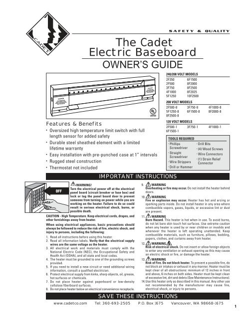
<strong>The</strong> <strong>Cadet</strong><br />
<strong>Electric</strong> <strong>Baseboard</strong><br />
OWNER’S GUIDE<br />
Features & Benefits<br />
• Oversized high temperature limit switch with full<br />
length sensor for added safety<br />
• Durable steel sheathed element with a limited<br />
lifetime warranty<br />
• Easy installation with pre-punched case at 1” intervals<br />
• Rugged steel construction<br />
• <strong>The</strong>rmostat not included<br />
WARNING!<br />
Turn the electrical power off at the electrical<br />
panel board (circuit breaker or fuse box) and<br />
lock or tag the panel board door to prevent<br />
someone from turning on power while you are<br />
working on the heater. Failure to do so could<br />
result in serious electrical shock, burns, or<br />
possible death.<br />
CAUTION - High Temperature. Keep electrical cords, drapes, and<br />
other furnishings away from heater.<br />
When using electrical appliances, basic precautions should<br />
always be followed to reduce the risk of fire, electric shock, and<br />
injury to persons, including the following:<br />
1. Read all instructions before using this heater.<br />
2. Read all information labels. Verify that the electrical supply<br />
wires are the same voltage as the heater.<br />
3. All electrical work and materials must comply with the<br />
National <strong>Electric</strong> Code (NEC), the Occupational Safety and<br />
Health Act (OSHA), and all state and local codes.<br />
4. <strong>The</strong> heater must be grounded to one of the grounding screws<br />
provided.<br />
5. If you need to install a new circuit or need additional wiring<br />
information, consult a qualified electrician.<br />
6. Protect electrical supply from kinks, sharp objects, oil, grease,<br />
hot surfaces or chemicals.<br />
7. Do not place heater against paperboard or low-density<br />
cellulose fiberboard surfaces.<br />
8. Do not place heater below an electrical convenience receptacle.<br />
IMPORTANT INSTRUCTIONS<br />
SAVE THESE INSTRUCTIONS<br />
240/208 VOLT MODELS<br />
2F350 6F1500<br />
2F500 8F2000<br />
3F750 8F2500<br />
4F1000 8F2025<br />
5F1250 10F2500<br />
208 VOLT MODELS<br />
2F500-8 3F750-8 4F1000-8<br />
5F1250-8 6F1500-8 8F2000-8<br />
8F2500-8<br />
120 VOLT MODELS<br />
2F500-1 3F750-1 4F1000-1<br />
6F1500-1<br />
TOOLS REQUIRED<br />
• • Phillips<br />
Drill Bits<br />
Screwdriver<br />
• (4) Wood Screws<br />
• Straight<br />
• Wire Connectors<br />
Screwdriver<br />
• (1) Strain Relief<br />
• Wire Strippers Connector<br />
• Drill or Hammer<br />
9. WARNING<br />
Overheating or fire may occur. Do not install the heater behind<br />
doors.<br />
10. WARNING<br />
Fire or explosion may occur. Heater has hot and arcing or<br />
sparking parts inside. Do not install heater in any area where<br />
combustible vapors, gases, liquids, or excessive lint or dust<br />
are present.<br />
11. WARNING<br />
Burn Hazard. This heater is hot when in use. To avoid burns,<br />
do not let bare skin touch hot surfaces. Use extreme caution<br />
when any heater is used by or near children or invalids and<br />
whenever the heater is left operating unattended. Keep<br />
combustible materials, such as furniture, pillows, bedding,<br />
papers, clothes, and curtains away from heater.<br />
12. WARNING<br />
Risk of electrical shock. Do not insert or allow foreign objects<br />
to enter any ventilation or exhaust opening as this may cause<br />
an electric shock or fire, or damage the heater.<br />
13. WARNING<br />
Risk of Fire. Do not block heater. To prevent a possible fire, do<br />
not block air intakes or exhaust in any manner. Heater must be<br />
kept clear of all obstructions: minimum of 12 inches in front<br />
and above, 6 inches on both sides. Heater must be kept clean<br />
of excessive lint, dirt and debris (See Maintenance Instructions).<br />
14.Use this heater only as described in this manual. Any other use<br />
not recommended by the manufacturer may cause fire,<br />
electrical shock, or injury to persons.<br />
www.cadetco.com Tel: 360-693-2505 P.O. Box 1675 Vancouver, WA 98668-1675<br />
1
2<br />
ABOUT THE CADET ELECTRIC BASEBOARD: <strong>The</strong> <strong>Cadet</strong> <strong>Electric</strong> <strong>Baseboard</strong> is designed to provide zonal heat to a room by using convection to<br />
naturally circulate warm air. Safety is <strong>Cadet</strong>’s first priority. All F-Series electric baseboards feature an oversized high temperature limit switch<br />
with a full length capillary sensor tube that temporarily shuts the heater off when excessive operating temperatures are detected. For effective<br />
and safe operation, and to prolong the life of the heater, read all instructions and safety information, and follow the maintenance instructions<br />
in this Owner’s Guide.<br />
BEFORE PROCEEDING WITH THE INSTALLATION INSTRUCTIONS, YOU MUST<br />
CONSIDER SEVERAL FACTORS THAT ARE CRITICAL TO INSTALLATION<br />
See our How-To Video at http://cadetco.com/installationvideo.php<br />
THERMOSTAT<br />
A thermostat is required. A <strong>Cadet</strong> wall thermostat is recommended<br />
for optimum performance, or you may prefer the convenience of a<br />
built-in thermostat kit. For instructions on wiring a thermostat, see<br />
the instructions that were included with your thermostat. If you<br />
are installing a wall thermostat, refer to the section later in this<br />
guide titled “<strong>Baseboard</strong> Wiring With a Wall <strong>The</strong>rmostat” prior to<br />
installing the baseboard.<br />
PLACEMENT<br />
For best results, install the baseboard heater under a window,<br />
along an outside wall, or as close as possible to an outside door.<br />
Follow these instructions for selecting an ideal area of installation:<br />
DO NOT INSTALL ANY BASEBOARD<br />
BELOW AN ELECTRICAL OUTLET<br />
DO NOT INSTALL ANY BASEBOARD VERTICALLY.<br />
MOUNT THE BASEBOARD HORIZONTALLY ONLY<br />
Installation Instructions<br />
• <strong>The</strong> seam at the junction of the wall and floor behind the heater<br />
should be caulked to prevent dust from being drawn into the room.<br />
• Heater should be set flush against surface of the wall.<br />
• Remove any obstructions between the back of the unit and the<br />
surface of the wall.<br />
• <strong>Baseboard</strong> heater may sit directly on any floor surface, including<br />
carpet.<br />
• Do not allow carpet to block lower air intake located 1 inch from<br />
the bottom.<br />
• Maintain at least 12 inches minimum clearance from objects hanging<br />
above (i.e. drapes).<br />
WIRING<br />
Wire connection is possible from either right or left side of the<br />
baseboard heater. Determine which side of the baseboard you are<br />
making wire connections by locating the supply wires. You must<br />
locate the supply wires before mounting the heater. See section<br />
titled “<strong>Baseboard</strong> Wiring With a Wall <strong>The</strong>rmostat” prior to wiring<br />
the baseboard if you are installing a wall thermostat.<br />
VOLTAGE (ALL MODELS)<br />
It is extremely important that you verify the electrical supply wires<br />
are the same voltage as the heater (i.e. 120 volt heater to 120 volt<br />
power supply and 240 volt heater to 240 volt power supply). If replacing<br />
an existing heater check the labels of the old heater and replace<br />
using same voltage. Hooking a 240 volt heater to a 120 volt power<br />
supply will drastically reduce the heater’s output. Hooking a 120 volt<br />
heater to a 240 volt power supply will destroy the heater.<br />
WATTAGE (FOR MODEL 8F2025)<br />
Model 8F2025 is a multi-watt unit configured for either 2500 or 2000<br />
watts. <strong>The</strong> heater is factory set for 2500 watts, but the instructions<br />
vary depending on your desired wattage and which side you are<br />
wiring. Make sure you follow the directions in the Owner’s Guide<br />
for your specific application. It is best to decide on your desired<br />
wattage prior to installing the baseboard.
STEP 1: Mount Heater to Wall<br />
1. Locate wall studs closest to supply wires and position heater<br />
(See Figure 1). NOTE: Wire connection is possible from either right<br />
or left side of the baseboard heater.<br />
Figure 1<br />
FINISHED<br />
WALL<br />
SUPPLY<br />
WIRES<br />
STUDS<br />
FLOOR<br />
Installation Instructions<br />
SUPPLY<br />
2. Remove the wiring compartment cover by removing the screw<br />
(See Figure 2). <strong>The</strong> wiring compartment is an approved junction<br />
box for the baseboard only. No additional junction box is required.<br />
3. Remove the slotted knockout closest to the sup ply wires and install<br />
a strain relief connector (See Figure 3).<br />
4. Pull supply wires through the connector and secure leaving 6 inch<br />
wire leads for later use (See Figure 4).<br />
JUNCTION BOX<br />
GROUND SCREW<br />
Figure 2<br />
WIRING<br />
COMPARTMENT<br />
COVER<br />
Figure 3<br />
Figure 4<br />
5. Mount the heater securely to the wall with nails or screws going into at<br />
least two wall studs (See Figure 5). <strong>The</strong> back of the heater has “star punch”<br />
dimples that allow nails or screws to easily pierce the sheet metal.<br />
Figure 5<br />
WIRING<br />
COMPARTMENT COVER<br />
MOUNT<br />
SECURELY<br />
TO WALL<br />
NOTE: You do not need to disassemble any additional parts to mount<br />
the heater.<br />
6. Connect the grounding lead to the grounding screw (See Figure 4).<br />
Both sides of the heater include a grounding screw.<br />
STEP 2: <strong>Baseboard</strong> Wiring<br />
1. Verify the electrical supply wires are the same voltage as the<br />
heater. Check heater specifications to ensure correct wiring.<br />
Failure to do so may destroy the heater and void your warranty.<br />
Both 120 volt and 240 volt baseboard wiring utilize 3 supply wires.<br />
120 volt baseboard wiring: 1 hot, 1 neutral and 1 ground.<br />
240 volt baseboard wiring: 2 hot and 1 ground. No neutral needed.<br />
For all baseboard wiring applications, both supply wires must be<br />
connected to at least one (1) heater wire.<br />
2. Disconnect ONLY one factory connector (See Figure 6. Model<br />
8F2025 See Figure 7). If wiring on the left side, disconnect factory<br />
connector A. If wiring on the right side, disconnect factory<br />
connector B.<br />
NOTE: <strong>The</strong>re are no loose wires provided with the baseboard.<br />
This is due to the ability to wire the baseboard on either the right<br />
or left side of the heater.<br />
A<br />
A<br />
B<br />
DO NOT DISCONNECT ONNECT GROUND<br />
B<br />
DO NOT DISCONNECT GROUND<br />
3. Proceed to the next step.<br />
STUDS<br />
Figure 6<br />
Figure 7<br />
Model<br />
8F2025<br />
Only<br />
3
4<br />
STEP 2: <strong>Baseboard</strong> Wiring (continued)<br />
STANDARD BASEBOARD WIRING ON RIGHT SIDE<br />
120V OR 240V SUPPLY (See Figure 8)<br />
1. Connect one supply wire to one heater wire.<br />
2. Connect remaining supply wire to remaining heater wire.<br />
3. Replace wiring compartment cover and secure with screw<br />
previously removed.<br />
4. Turn power back on at the electrical panel board.<br />
STANDARD BASEBOARD WIRING ON LEFT SIDE<br />
120V OR 240V SUPPLY (See Figure 9)<br />
1. Connect one supply wire to one heater wire.<br />
2. Connect remaining supply wire to remaining heater wire.<br />
3. Replace wiring compartment cover and secure with screw<br />
previously removed.<br />
4. Turn power back on at the electrical panel board.<br />
MULTI-WATT BASEBOARDS: WIRING ON RIGHT SIDE<br />
MODEL 8F2025 (See Figure 10)<br />
1. Connect one supply wire to one heater wire.<br />
2. Connect remaining supply wire to remaining heater wire.<br />
3. Replace wiring compartment cover and secure with screw<br />
previously removed.<br />
4. Selecting desired wattage<br />
a. For 2500 watt applications: No action is required.<br />
Heater is factory set for 2500 watts.<br />
b. For 2000 watt applications: Remove left wiring compartment<br />
cover. Cut red wire and cap both loose ends with<br />
approved wire connectors, or wrap both loose ends<br />
with electrical tape. Replace wiring compartment cover<br />
and secure with screw previously removed.<br />
5. Turn power back on at the electrical panel board.<br />
Installation Instructions<br />
Refer to the wiring diagram below that corresponds to your heater application.<br />
For single wattage baseboards, refer to “Standard <strong>Baseboard</strong>s.”<br />
For multi-watt baseboards, refer to “Multi-Watt <strong>Baseboard</strong>s.”<br />
(Important: connect supply ground wire directly to one of the ground screws<br />
provided on either side of the baseboard heater.)<br />
MULTI-WATT BASEBOARDS: WIRING ON LEFT SIDE<br />
MODEL 8F2025 (See Figure 11)<br />
1. Disconnect splice/wire connector without the red wire.<br />
2. Connect one supply wire to the upper black wire.<br />
3. Connect the other supply wire to the lower black wire.<br />
4. Selecting desired wattage:<br />
a. For 2500 watt applications: No action is required. Heater is<br />
factory set for 2500 watts.<br />
b. For 2000 watt applications: Cut red wire and cap both loose<br />
ends with an approved wire connector, or wrap loose ends<br />
with electrical tape.<br />
5. Replace wiring compartment cover and secure with screw<br />
previously removed.<br />
6. Turn power back on at the electrical panel board.<br />
Supply Wires<br />
Side ʻAʼ Shown<br />
Ground<br />
Red<br />
Wire<br />
Supply Wires<br />
DO NOT<br />
DISCONNECT<br />
Side ʻAʼ Shown<br />
Ground<br />
<strong>Baseboard</strong> Heater<br />
Red Wire<br />
Model 8F2025 -<br />
Factory set for<br />
2500 watts<br />
To Supply<br />
To Supply<br />
<strong>Baseboard</strong> Heater<br />
2000 Watt Configuration<br />
Left Side of <strong>Baseboard</strong> Shown<br />
To Supply<br />
Red Wire<br />
<strong>Baseboard</strong> Heater<br />
To Supply<br />
DO NOT DISCONNECT<br />
<strong>Baseboard</strong> Heater<br />
Supply Wires<br />
Side ʻBʼ Shown<br />
Ground<br />
Red<br />
Wire<br />
Figure 8<br />
Right Side<br />
Wiring Shown<br />
Figure 9<br />
Left Side<br />
Wiring Shown<br />
Figure 10<br />
Right Side<br />
Wiring Shown<br />
Supply Wires<br />
Side ʻBʼ Shown<br />
Ground<br />
Figure 11<br />
Left Side<br />
Wiring Shown<br />
Red<br />
Wire<br />
2000 Watt Configuration<br />
Left Side of <strong>Baseboard</strong> Shown
MULTIPLE BASEBOARD WIRING. 240V SUPPLY ONLY<br />
(See Figure 14)<br />
1. Left side wiring: disconnect factory connector A.<br />
Right side wiring: disconnect factory connector B.<br />
B<br />
2. Connect one wire from each heater to one supply wire.<br />
3. Connect remaining wire from each heater to the remaining<br />
supply wire.<br />
4. Connect supply ground wire to both ground screws using<br />
appropriate guage wire.<br />
Note: Field wiring is not provided<br />
<strong>Baseboard</strong> wiring with a wall thermostat - Optional<br />
Refer to the wiring diagram below that corresponds to your thermostat application. Note: Wiring diagrams are for reference only. See wall<br />
thermostat instructions included with your thermostat for your specific application.<br />
For instructions on wiring using an in-built thermostat, see <strong>Cadet</strong> BTF1, BTF2 and SBFT2 Installation Instructions<br />
SINGLE POLE WALL THERMOSTAT<br />
1. Route supply wires to the thermostat wiring box (if not already<br />
present).<br />
2. Connect one supply wire to one thermostat wire (typically<br />
marked L1).<br />
3. Route remaining thermostat wire (typically marked T1)<br />
to the baseboard heater.<br />
4. Route remaining supply and ground wire to the baseboard heater.<br />
5. Follow installation instructions for mounting and wiring<br />
baseboard heater.<br />
DOUBLE POLE WALL THERMOSTAT<br />
1. Route supply wires to the thermostat wiring box (if not already<br />
present).<br />
2. Connect one supply wire to one thermostat wire (typically<br />
marked L1).<br />
3. Connect remaining supply wire to other thermostat wire (typically<br />
marked L2).<br />
4. Route remaining thermostat wires (typically marked T1 and T2)<br />
to the baseboard heater.<br />
5. Route ground wire to the baseboard heater.<br />
6. Follow installation instructions for mounting and wiring<br />
baseboard heater.<br />
Multiple <strong>Baseboard</strong> Wiring - Optional<br />
Follow the instructions below if you are wiring more than one heater in parallel on same circuit.<br />
If you are wiring multiple baseboards to one control, it is recommended that you use one control per room.<br />
A<br />
<strong>Baseboard</strong> Heater<br />
Right Side<br />
<strong>The</strong>rmostat<br />
wiring box<br />
<strong>The</strong>rmostat<br />
wiring box<br />
B<br />
To Supply<br />
To Heater<br />
To Supply<br />
To Heater<br />
To Wall <strong>The</strong>rmostat<br />
Heater Ground Field Wiring<br />
Wires<br />
L1<br />
T1<br />
LOW<br />
OFF<br />
A<br />
L2<br />
T2<br />
L1<br />
Field<br />
Wiring Ground<br />
T1<br />
Figure 12<br />
Single Pole<br />
<strong>The</strong>rmostat<br />
Figure 13<br />
Double Pole<br />
<strong>The</strong>rmostat<br />
Figure 14<br />
STANDARD<br />
BASEBOARDS<br />
SHOWN<br />
<strong>Baseboard</strong> Heater<br />
Left Side<br />
Do not disconnect<br />
5
6<br />
How To Operate Your Heater<br />
1. Heater must be properly installed before it is used. Switch the<br />
power on at the electrical panel board. PLEASE NOTE: Upon<br />
initial start-up, the heater may emit a burning odor. This is not<br />
dangerous, and is due to a protective lubricant used during the<br />
manufacturing process. It typically dissipates within several hours.<br />
2. Turn the thermostat fully clockwise.<br />
3. When the room reaches your comfort level, turn the thermostat<br />
knob counterclockwise until a clicking sound is heard (if using<br />
a digital thermostat, set at desired room temperature). <strong>The</strong><br />
baseboard will automatically cycle around this preset temperature.<br />
CONSULT LOCAL ELECTRICAL CODES TO DETERMINE WHAT WORK MUST BE PERFORMED BY QUALIFIED ELECTRICAL SERVICE PERSONNEL<br />
Symptom Problem Solution<br />
Snapping noise<br />
Heater not working<br />
Heater will not shut off<br />
Black streaks (sooting)<br />
depositing on baseboard,<br />
walls, and drapes<br />
1. Unit may have a loose end plate<br />
Troubleshooting Chart<br />
2. Heater may not be mounted properly<br />
1. Heater does not have proper voltage<br />
to function correctly<br />
2. Loose wire connections<br />
3. Incorrect circuit breaker<br />
4. Defective limit<br />
1. Heat loss from room is greater than<br />
heater capacity<br />
2. Defective thermostat<br />
3. <strong>The</strong>rmostat wired incorrectly to heater<br />
4. Temperature in room lower than<br />
thermostat’s lowest setting<br />
1. Excessive hydrocarbons present in<br />
home environment*<br />
2. Not enough fresh air flowing through<br />
baseboard<br />
3. Streaking being allowed to build up<br />
on room surfaces<br />
1. Loosen end plate screws ¼ turn after allowing heater to warm, move end<br />
plate back and forth, then tighten<br />
2. Loosen heater from wall by turning mounting screws ¼ turn<br />
1. Check voltage at the heater between supply wires and make sure it<br />
matches required heater voltage<br />
2. Tighten any loose wire connections<br />
3. Circuit breaker positioned incorrectly - relocate breaker<br />
4. Replace limit<br />
1. Close doors and windows. Provide additional insulation, install a higherwattage<br />
heater or multiple heaters if necessary<br />
2. Adjust thermostat to its lowest setting. If heater continues to run<br />
(allow two minutes for the thermostat to respond), replace thermostat<br />
3. Refer to thermostat documentation and correct wiring<br />
4. Change thermostat to double pole model with positive off (single pole<br />
thermostats have a minimum temperature setting with no “off” position).<br />
1. Remove/reduce use of items emitting hydrocarbons. (Common sources:<br />
insect foggers, aerosol sprays, carpet cleaning chemicals, candles, plants,<br />
dust, cigarette smoke and fireplaces)<br />
2. Increase amount of fresh air available in room. Do not use heater during<br />
any chemical usage (insect fogging, carpet cleaning, etc.) and allow for<br />
outside air exchange before re-use of heater(s)<br />
3. More frequent cleaning of streaking to reduce amount of build-up<br />
* Black soot and residue is formed by the combustion of hydrocarbons. Existing hydrocarbons in environment pass through heater element and scorch,<br />
exit the heater and deposit on walls and room surfaces. Note: <strong>The</strong> heater itself does not produce/release any hydrocarbons.<br />
Maintenance: For more effective and safer operation and to prolong the<br />
life of the heater, read the Owner’s Guide and follow the maintenance<br />
instructions included with each heater. Failure to properly maintain<br />
the heater will void any warranty and may cause the heater to function<br />
improperly. Warranties are non transferable and apply to original<br />
consumer only. Warranty terms are set out below.<br />
LIMITED LIFETIME WARRANTY: <strong>Cadet</strong> will repair or replace any<br />
<strong>Cadet</strong> baseboard (F) found to be defective at any time.<br />
THESE WARRANTIES DO NOT APPLY:<br />
1. Damage occurs to the product through improper installation or<br />
incorrect supply voltage;<br />
2. Damage occurs to the product through improper maintenance,<br />
misuse, abuse, accident, or alteration;<br />
3. <strong>The</strong> product is serviced by anyone other than <strong>Cadet</strong>;<br />
4. If the date of manufacture of the product cannot be determined;<br />
5. If the product is damaged during shipping through no fault<br />
of <strong>Cadet</strong>.<br />
6. CADET’S WARRANTY IS LIMITED TO REPAIR OR REPLACEMENT AS<br />
SET OUT HEREIN. CADET SHALL NOT BE LIABLE FOR DAMAGES<br />
SUCH AS PROPERTY DAMAGE OR FOR CONSEQUENTIAL DAMAGES<br />
AND/OR INCIDENTAL EXPENSES RESULTING FROM BREACH OF<br />
THESE WRITTEN WARRANTIES OR ANY EXPRESS OR IMPLIED<br />
WARRANTY.<br />
7. IN THE EVENT CADET ELECTS TO REPLACE ANY PART OF YOUR<br />
CADET PRODUCT, THE REPLACEMENT PARTS ARE SUBJECT TO THE<br />
Operation & Maintenance<br />
WARRANTY<br />
Maintenance<br />
<strong>Cadet</strong> electric baseboards are virtually maintenance-free. However,<br />
a certain amount of lint and dust will accumulate inside the unit<br />
and should be periodically cleaned:<br />
1. Turn the electrical power off at the electrical panel board (circuit<br />
breaker or fuse box) and lock or tag the panel board door to<br />
prevent someone from turning on power while you are working<br />
on the heater. Failure to do so could result in serious electrical<br />
shock, burns, or possible death. Wait to service or maintain the<br />
heater until the element is cool.<br />
2. Vacuum inside the unit, being careful not to damage the aluminum<br />
fins on the heat exchanger.<br />
3. Power can be restored once cleaning work is complete.<br />
SAME WARRANTIES AS THE PRODUCT. THE INSTALLATION OF<br />
REPLACEMENT PARTS DOES NOT MODIFY OR EXTEND THE UNDERLYING<br />
WARRANTIES. REPLACEMENT OR REPAIR OF ANY CADET PRODUCT<br />
OR PART DOES NOT CREATE ANY NEW WARRANTIES.<br />
8. <strong>The</strong>se warranties give you specific legal rights, and you may<br />
also have other rights which vary from state to state. <strong>Cadet</strong><br />
neither assumes, nor authorizes anyone to assume for it, any<br />
other obligation or liability in connection with its products other<br />
than as set out herein.<br />
If you believe your <strong>Cadet</strong> product is defective, please contact <strong>Cadet</strong><br />
Manufacturing Co. at 360-693-2505, during the warranty period, for<br />
instructions on how to have the repair or replacement processed.<br />
Warranty claims made after the warranty period has expired will<br />
be denied. Products returned without authorization will be refused.<br />
Parts and Service<br />
Visit http://support.cadetco.com for information on where to obtain<br />
parts and service.<br />
Reduce-Reuse-Recycle<br />
This product is made primarily of recyclable materials. You<br />
can reduce your carbon footprint by recycling this product<br />
at the end of its useful life. Contact your local recycling<br />
support center for further recycling instructions.<br />
©2012 <strong>Cadet</strong> Manufacturing Co. Printed in U.S.A. 2/12 #720001
Calentador Eléctrico<br />
de Plinto Radiante <strong>Cadet</strong><br />
GUÍA PARA EL PROPIETARIO<br />
Características y Beneficios<br />
• Interruptor de límite de alta temperatura de gran tamaño<br />
con sensor de plena longitud para mayor seguridad<br />
• Durable elemento envainado de acero con garantía<br />
vitalicia limitada<br />
• Fácil instalación con caja perforada a intervalos de 1”<br />
• Construcción de acero reforzado<br />
• No se incluye el termostato<br />
¡ADVERTENCIA!<br />
Desconecte la electricidad en el tablero del<br />
panel eléctrico (cortacircuito o caja de fusibles)<br />
y trabe o coloque un cartel en la puerta<br />
del tablero del panel para evitar que alguien<br />
vuelva a conectar la energía mientras se esté<br />
trabajando en el calentador. De lo contrario<br />
podrían producirse graves golpes eléctricos,<br />
quemaduras e incluso la muerte.<br />
PRECAUCIÓN – Alta temperatura. Mantenga los cables eléctricos,<br />
cortinas y demás mobiliario lejos del calentador.<br />
Al utilizar artefactos eléctricos, siempre se deben adoptar<br />
precauciones básicas para reducir el riesgo de incendios,<br />
electrocución y lesiones personales, incluyendo lo siguiente:<br />
1. Lea todas las instrucciones antes de usar este calentador.<br />
2. Lea todas las etiquetas que contengan información. Verifique<br />
que todos los alambres de suministro eléctrico sean del mismo<br />
voltaje que el calentador.<br />
3. Todo trabajo y materiales eléctricos deben cumplir con el<br />
Código Eléctrico Nacional (“NEC”, por su sigla en inglés), con<br />
la Ley de Seguridad y Salud Ocupacional (“OSHA”, por su sigla<br />
en inglés) y con todos los códigos estatales y locales.<br />
4. El calentador debe estar conectado a uno de los tornillos de<br />
puesta a tierra suministrados.<br />
5. Si se debe instalar un nuevo circuito o se necesita información<br />
adicional sobre el cableado, consulte a un electricista calificado.<br />
6. Evite que los alambres de suministro eléctrico se retuerzan o<br />
entren en contacto con objetos afilados, aceite, grasa, superficies<br />
calientes o sustancias químicas.<br />
7. No coloque el calentador apegado a superficies de cartulina o<br />
de fibra de celulosa de baja densidad.<br />
8. No coloque el calentador bajo un tomacorriente.<br />
INFORMACIÓN IMPORTANTE<br />
CONSERVE ESTAS INSTRUCCIÓNES<br />
MODELOS DE 240/208 VOLTIOS<br />
2F350 6F1500<br />
2F500 8F2000<br />
3F750 8F2500<br />
4F1000 8F2025<br />
5F1250 10F2500<br />
MODELOS DE 208 VOLTIOS<br />
2F500-8 3F750-8 4F1000-8<br />
5F1250-8 6F1500-8 8F2000-8<br />
8F2500-8<br />
MODELOS DE 120 VOLTIOS<br />
2F500-1 3F750-1 4F1000-1<br />
6F1500-1<br />
HERRAMIENTAS REQUERIDAS<br />
• Destornillador<br />
Phillips<br />
• Destornillador<br />
Plano<br />
• Pelacables<br />
• Taladro o Martillo<br />
• Brocas<br />
• (4) Tornillos<br />
Para Madera<br />
• Conectores<br />
de alambres<br />
• (1) Conector de<br />
Alivio de Tensión<br />
9. ¡ADVERTENCIA!<br />
Podría producirse recalentamiento o un incendio. No instale el<br />
calentador detrás de alguna puerta.<br />
10. ¡ADVERTENCIA!<br />
Podrían producirse explosiones o incendios. El calentador está<br />
caliente y contiene piezas que producen arcos voltaicos o chispas.<br />
No lo instale en áreas donde exista la presencia de vapores, gases<br />
o líquidos combustibles o exceso de pelusas o polvo.<br />
11. ¡ADVERTENCIA!<br />
Riesgo de quemaduras. Este calentador se calienta mucho cuando<br />
está en uso. Para evitar quemaduras, no lo toque con su piel<br />
descubierta. Tenga mucho cuidado cuando use el calentador en o<br />
cerca de niños o de personas inválidas, y cada vez que lo deje<br />
funcionando sin vigilancia. Mantenga los materiales combustibles<br />
tales como muebles, cojines, camas, papeles, ropas y cortinas lejos<br />
del calentador.<br />
12. ¡ADVERTENCIA!<br />
Riesgo de electrocución. No introduzca ni permita que ingresen<br />
objetos en las aberturas de la ventilación o escape, ya que ello<br />
puede causar electrocución o incendio, o bien dañar el calentador.<br />
13. ¡ADVERTENCIA!<br />
Riesgo de incendio. No bloquee el calentador. Para evitar posibles<br />
incendios, no bloquee las tomas de aire ni el escape de manera<br />
alguna. El calentador debe mantenerse sin obstrucciones: un<br />
mínimo de 12 pulgadas por delante y por encima, y 6 pulgadas<br />
en cada costado. Los calentadores deben mantenerse sin<br />
pelusas, suciedad ni residuos excesivos. (Consulte las instrucciones<br />
de mantenimiento)<br />
14.Use este calentador sólo como se describe en este manual.<br />
Todo otro uso no recomendado por el fabricante puede causar<br />
incendios, descargas eléctricas o lesiones personales.<br />
www.cadetco.com Tel: 360-693-2505 P.O. Box 1675 Vancouver, WA 98668-1675<br />
7
8<br />
ACERCA DEL ZÓCALO ELÉCTRICO CADET: El zócalo eléctrico <strong>Cadet</strong> está diseñado para brindar calor zonal a una habitación usando convección a<br />
fin de hacer circular el aire caliente en forma natural. La seguridad es la principal prioridad de <strong>Cadet</strong>. Todos los zócalos eléctricos de la serie F<br />
cuentan tanto con un interruptor límite de alta temperatura y gran tamaño como con un tubo sensor capilar de plena longitud que apaga provisoriamente<br />
el calentador cuando se detectan temperaturas de funcionamiento excesivas. Para una operación eficaz y segura, y para prolongar la vida útil del<br />
calentador, lea todas las instrucciones e información de seguridad y acate las instrucciones de mantenimiento de la presente Guía del propietario.<br />
ANTES DE PROCEDER CON LAS INSTRUCCIONES DE INSTALACIÓN, DEBE<br />
CONSIDERAR VARIOS FACTORES QUE SON FUNDAMENTALES PARA LA MISMA<br />
TERMOSTATO<br />
Se requiere un termostato. Se recomienda un termostato mural <strong>Cadet</strong><br />
para un óptimo rendimiento, o bien puede optar por la comodidad<br />
de un juego de termostato incorporado. En las instrucciones incluidas<br />
con el termostato encontrará información sobre el cableado del<br />
mismo. Si va a instalar un termostato mural, antes de instalar el<br />
zócalo consulte la sección “Cableado del zócalo con un termostato<br />
mural” en esta guía.<br />
UBICACIÓN<br />
Para mejores resultados, instale el calentador de zócalo bajo una<br />
ventana, junto a una pared exterior o lo más cerca posible de una<br />
puerta que dé al exterior. Siga estas instrucciones para seleccionar<br />
un área de instalación ideal:<br />
NO INSTALE NINGÚN ZÓCALO DEBAJO<br />
DE UN TOMACORRIENTE ELÉCTRICO<br />
NO INSTALE NINGÚN ZÓCALO EN FORMA VERTICAL.<br />
MÓNTELO EN FORMA HORIZONTAL SOLAMENTE<br />
Instrucciones Para La Instalación<br />
Consulte nuestro video informativo en http://cadetco.com/installationvideo.php<br />
• La unión donde confluyen la pared y el piso detrás de los calentadores<br />
se debe calafatear para evitar el ingreso de polvo a la habitación.<br />
• El calentador se debe instalar a ras de la superficie de la muralla.<br />
• Retire toda obstrucción entre la parte trasera de la unidad y la<br />
superficie de la pared.<br />
• El calentador de zócalo puede instalarse directamente en la<br />
superficie de cualquier tipo de piso, incluyendo alfombra.<br />
• No deje que la alfombra obstruya la toma de aire inferior situada<br />
a 1 pulgada del piso.<br />
• Mantenga por lo menos un espaciado mínimo de 12 pulgadas respecto<br />
de los objetos que cuelguen por encima (por ejemplo, cortinas).<br />
PARED ADYACENTE<br />
Espaciado mínimo de 12”<br />
CABLEADO<br />
La conexión de los alambres se puede hacer ya sea por el lado<br />
derecho o izquierdo del calentador de zócalo. Determine el lado<br />
por el cual hará las conexiones ubicando los cables de suministro.<br />
Debe ubicar los cables antes de montar el calentador. Si va<br />
a instalar un termostato mural, antes de cablear el zócalo consulte<br />
la sección “Cableado del zócalo con un termostato mural”.<br />
VOLTAJE (TODOS LOS MODELOS)<br />
Es extremadamente importante verificar que los cables de suministro<br />
eléctrico sean del mismo voltaje que el calentador (es decir, un<br />
calentador de 120 voltios con un suministro de energía del mismo<br />
voltaje, y un calentador de 240 voltios con un suministro de energía<br />
de ese mismo valor). Si va a reemplazar un calentador existente,<br />
revise las etiquetas del calentador antiguo y sustitúyalo por otro<br />
del mismo voltaje. Si se conecta un calentador de 240 voltios a un<br />
suministro de energía de 120 voltios, se reducirá drásticamente el<br />
rendimiento del calentador. Si se conecta un calentador de 120 voltios<br />
a un suministro de energía de 240 voltios, se destruirá el calentador.<br />
VATIAJE (PARA EL MODELO 8F2025)<br />
El modelo 8F2025 es una unidad de vatiaje múltiple configurada para<br />
2500 ó 2000 vatios. El calentador viene fijado de fábrica en 2500 vatios,<br />
sin embargo las instrucciones pueden variar dependiendo del vatiaje<br />
deseado y el lado en que se cablee. Cerciórese de acatar las<br />
indicaciones de la Guía del propietario para su aplicación específica.<br />
Antes de instalar el zócalo decida primero el vatiaje deseado.
PASO 1: Montaje mural del calentador<br />
1.Ubique los puntales de la pared que estén más cerca de los cables<br />
de suministro y luego coloque el calentador (consulte la figura 1).<br />
NOTA: La conexión de los cables se puede hacer ya sea por el lado<br />
derecho o izquierdo del calentador de zócalo.<br />
Figura 1<br />
PARED<br />
TERMINADA<br />
CABLES DE<br />
SUMINISTRO<br />
PUNTALES<br />
PISO<br />
Instrucciones Para La Instalación<br />
SUMINISTRO<br />
2. Retire la tapa del compartimiento de cableado quitando el tornillo<br />
(consulte la figura 2). Dicho compartimiento es una caja de<br />
conexiones aprobada sólo para el zócalo. No se requiere una<br />
caja de empalmes adicional.<br />
3. Retire el destapadero ranurado más cercano a los cables de suministro<br />
e instale un conector con alivio de la tensión (consulte la figura 3).<br />
DESTAPADERO<br />
(GIRE PARA RETIRAR)<br />
CONECTOR DE ALIVIO<br />
DE TENSIÓN<br />
4. Tire los cables de suministro por el conector y fíjelos dejando que<br />
sobresalgan 6 pulgadas para su uso posterior (consulte la figura 4).<br />
CAJA DE EMPALMES<br />
Figura 2<br />
TAPA DEL<br />
COMPARTIMIENTO<br />
DE CABLEADO<br />
Figura 3<br />
Figura 4<br />
TORNILLO DE PUESTA<br />
A TIERRA<br />
5. Monte el calentador de manera firme en la pared con clavos o tornillos<br />
que se inserten en al menos dos puntales (consulte la figura 5). La<br />
parte trasera del calentador tiene orificios con forma de estrella que<br />
permiten penetrar fácilmente la placa metálica con clavos o tornillos.<br />
Figura 5<br />
TAPA DEL<br />
COMPARTIMIENTO<br />
DE CABLEADO<br />
MONTAJE<br />
MURAL<br />
SEGURO<br />
NOTA: No es necesario desarmar ninguna pieza adicional para montar<br />
el calentador.<br />
A<br />
B<br />
NO DO DESCONECTE NOT DISCONNECT<br />
GROUND TIERRA<br />
3. Prosiga con el paso siguiente.<br />
PUNTALES<br />
PASO 2: Cableado del zócalo<br />
1. Verifique que todos los cables de suministro eléctrico sean del<br />
mismo voltaje que el calentador. Revise las especificaciones del<br />
calentador para cerciorarse de realizar el cableado correcto. En<br />
caso contrario, podría destruir el calentador e invalidar la garantía.<br />
El cableado del zócalo tanto de 120 voltios como el de 240 usa 3<br />
cables de suministro.<br />
Cableado del zócalo de 120 voltios: 1 activo, 1 neutro y 1 a tierra<br />
Cableado del zócalo de 240 voltios: 2 activos y 1 a tierra. No requiere<br />
neutro.<br />
Para todas las aplicaciones de cableado de zócalos, ambos<br />
cables de suministro deben conectarse a por lo menos un<br />
(1) alambre del calentador.<br />
2. Desempalme un solo conector de fábrica (consulte la figura 6; para<br />
el modelo 8F2025. Consulte la figura 7). Si va a cablear en el lado<br />
izquierdo, desempalme el conector de fábrica A. Si va a cablear<br />
en el lado derecho, desempalme el conector de fábrica B.<br />
NOTA: El zócalo no se proporciona con cables sueltos. Ello<br />
se debe a la capacidad de cablear el zócalo ya sea en el lado<br />
derecho o izquierdo del calentador.<br />
A<br />
B<br />
NO<br />
DO<br />
DESCONECTE<br />
NOT DISCONNECT GROUND<br />
TIERRA<br />
Figura 6<br />
Figura 7<br />
Modelo<br />
8F2025<br />
solamente<br />
9
10<br />
Instrucciones Para La Instalación<br />
PASO 2: Cableado del zócalo (continuación)<br />
Consulte el siguiente diagrama de cableado que corresponda a su calentador.<br />
Para zócalos de vatiaje único consulte la sección “Zócalos estándar”.<br />
Para zócalos de vatiaje múltiple, consulte la sección “Zócalos de vatiaje múltiple”.<br />
(Importante: conecte el cable del suministro directamente a uno de los tornillos<br />
de puesta a tierra suministrados en cada lado del calentador de zócalo.)<br />
ZÓCALOS ESTÁNDAR: CABLEADO EN EL LADO DERECHO<br />
SUMINISTRO DE 120V Ó 240V (Consulte la figura 8)<br />
1. Conecte un cable de suministro a un alambre del calentador.<br />
2. Conecte el cable de suministro restante al otro alambre<br />
del calentador.<br />
3. Tape el compartimiento de cableado y afiáncelo con el tornillo<br />
que retiró anteriormente.<br />
4. Vuelva a conectar la alimentación en el tablero del panel eléctrico.<br />
ZÓCALOS ESTÁNDAR: CABLEADO EN EL LADO IZQUIERDO<br />
SUMINISTRO DE 120V Ó 240V (Consulte la figura 9)<br />
1. Conecte un cable de suministro a un alambre del calentador.<br />
2. Conecte el cable de suministro restante al otro alambre del<br />
calentador.<br />
3. Tape el compartimiento de cableado y afiáncelo con el tornillo<br />
que retiró anteriormente.<br />
4. Vuelva a conectar la alimentación en el tablero del panel eléctrico.<br />
ZÓCALOS DE VATIAJE MÚLTIPLE:<br />
CABLEADO EN EL LADO DERECHO<br />
MODELO 8F2025 (Consulte la figura 10)<br />
1. Conecte un cable de suministro a un alambre del calentador.<br />
2. Conecte el cable de suministro restante al otro alambre del<br />
calentador.<br />
3. Tape el compartimiento de cableado y afiáncelo con el tornillo<br />
que retiró anteriormente.<br />
4. Selección del vatiaje deseado<br />
a. Para aplicaciones de 2500 vatios: No se requiere ninguna<br />
acción. El calentador viene fijado de fábrica en 2500 vatios.<br />
b. Para aplicaciones de 2000 vatios: Retire la tapa del<br />
compartimiento de cableado izquierdo. Corte el alambre<br />
rojo y cubra los extremos sueltos con conectores de alambres<br />
aprobados o envuelva dichos extremos con cinta para uso<br />
eléctrico. Tape el compartimiento de cableado y afiáncelo<br />
con el tornillo que retiró anteriormente.<br />
5. Vuelva a conectar la alimentación en el tablero del panel eléctrico.<br />
ZÓCALOS DE VATIAJE MÚLTIPLE:<br />
CABLEADO EN EL LADO IZQUIERDO<br />
MODELO 8F2025 (Consulte la figura 11)<br />
1. Desenchufe un conector de empalme/alambre sin el alambre rojo.<br />
2. Conecte un cable de suministro al alambre negro superior.<br />
3. Conecte el alambre de suministro restante al otro alambre inferior.<br />
4. Selección del vatiaje deseado:<br />
a. Para aplicaciones de 2500 vatios: No se requiere ninguna<br />
acción. El calentador viene fijado de fábrica en 2500 vatios.<br />
b. Para aplicaciones de 2000 vatios: Corte el alambre rojo y cubra<br />
los extremos sueltos con un conector de alambres aprobado,<br />
o envuelva dichos extremos con cinta para uso eléctrico.<br />
5. Tape el compartimiento de cableado y afiáncelo con el tornillo<br />
que retiró anteriormente.<br />
6. Vuelva a conectar la alimentación en el tablero del panel eléctrico.<br />
Cables de<br />
suministro<br />
Aparece el lado ʻAʼ<br />
Tierra<br />
Alambre rojo<br />
Alambre<br />
rojo<br />
Cables de<br />
suministro<br />
Aparece el<br />
lado ʻAʼ<br />
Tierra<br />
Calentador de zócalo<br />
Al suministro<br />
Al suministro<br />
Calentador de zócalo<br />
Configuración de 2000 vatios<br />
Aparece el lado<br />
izquierdo del zócalo<br />
Al suministro<br />
Modelo 8F2025 –<br />
Fijado de fábrica<br />
en 2500 vatios<br />
Figura 8<br />
Aparece el cableado<br />
del lado derecho<br />
Cables de suministro<br />
Aparece el lado ʻBʼ<br />
Tierra<br />
Calentador de zócalo<br />
Al suministro<br />
NO DESCONECTAR<br />
Calentador de zócalo<br />
Alambre rojo<br />
NO<br />
DESCONECTAR<br />
Figura 9<br />
Aparece el<br />
cableado del<br />
lado izquierdo<br />
Figura 10<br />
Aparece el cableado<br />
del lado derecho<br />
Cables<br />
de suministro<br />
Aparece el lado ʻBʼ<br />
Tierra<br />
Figura 11<br />
Aparece el cableado<br />
del lado izquierdo<br />
Alambre<br />
rojo<br />
Alambre<br />
rojo<br />
Configuración de 2000 vatios<br />
Aparece el lado derecho del zócalo
Cableado de múltiples zócalos - Opcional<br />
Siga las instrucciones que se indican a continuación si va a cablear más de un calentador en paralelo en el mismo circuito.<br />
Si va a cablear múltiples zócalos a un solo control, se recomienda usar un control por habitación.<br />
CABLEADO DE MÚLTIPLES ZÓCALOS.<br />
SUMINISTRO DE 240V SOLAMENTE<br />
(Consulte la figura 14)<br />
1. Cableado del lado izquierdo: desempalme el conector<br />
B<br />
de fábrica A. Cableado del lado derecho: desempalme<br />
el conector de fábrica B.<br />
2. Conecte un alambre de cada calentador a un cable de<br />
suministro.<br />
3. Conecte el alambre restante de cada calentador al otro cable<br />
de suministro.<br />
4. Empalme el cable de conexión a tierra del suministro a ambos<br />
tornillos de puesta a tierra usando los calibres correctos.<br />
Nota: No se proporciona cableado de campo<br />
Cableado del zócalo con un termostato mural – Opcional<br />
Consulte el siguiente diagrama de cableado que corresponda a su termostato. Nota: Los diagramas de cableado son sólo de<br />
referencia. Consulte las instrucciones del termostato mural incluidas para su aplicación específica.<br />
Si desea información sobre el cableado usando un termostato incorporado, consulte las instrucciones de instalación de BTF1,<br />
BTF2 y SBFT2 de <strong>Cadet</strong><br />
TERMOSTATO MURAL DE UN SOLO POLO<br />
1. Tienda los cables de suministro a la caja de cableado del<br />
termostato (si no están presentes).<br />
2. Conecte un cable de suministro a un alambre del termostato<br />
(marcado comúnmente L1).<br />
3. Tienda el alambre restante del termostato (comúnmente<br />
marcado T1) al calentador de zócalo.<br />
4. Tienda el cable de suministro y puesta a tierra restante<br />
al calentador de zócalo.<br />
5. Siga las instrucciones de instalación para montar y cablear<br />
el calentador de zócalo.<br />
TERMOSTATO MURAL DE DOS POLOS<br />
1. Tienda los cables de suministro a la caja de cableado del<br />
termostato (si no están presentes).<br />
2. Conecte un cable de suministro a un alambre del termostato<br />
(marcado comúnmente L1).<br />
3. Conecte el cable de suministro restante al otro alambre<br />
del termostato (marcado comúnmente L2).<br />
4. Tienda los alambres restantes del termostato (comúnmente<br />
marcados T1 y T2) al calentador de zócalo.<br />
5. Tienda el cable de puesta a tierra al calentador de zócalo.<br />
6. Siga las instrucciones de instalación para montar y cablear el<br />
calentador de zócalo.<br />
A<br />
Al suministro<br />
Caja de cableado<br />
del<br />
termostato<br />
Al calentador<br />
Al suministro<br />
Caja de cableado<br />
del<br />
termostato<br />
Al calentador<br />
Lado derecho del<br />
calentador de zócalo<br />
B<br />
Alambres<br />
del Tierra<br />
calentador<br />
Al termostato<br />
mural<br />
Cableado<br />
de campo<br />
L1<br />
T1<br />
BAJO LOW<br />
APAGADO OFF<br />
Cableado<br />
de<br />
campo<br />
L1<br />
T1<br />
L2<br />
T2<br />
A<br />
Tierra<br />
Figura 12<br />
Termostato<br />
de un solo polo<br />
Figura 13<br />
Termostato<br />
de dos polos<br />
Figura 14<br />
APARECEN ZÓCALOS ESTÁNDAR<br />
Lado izquierdo<br />
del calentador<br />
de zócalo<br />
No desconecte<br />
11
12<br />
Cómo hacer funcionar el calentador<br />
1. El calentador debe instalarse correctamente antes de usarlo.<br />
Encienda la alimentación en el tablero del panel eléctrico.<br />
OBSERVE QUE: En el arranque inicial, el calentador puede expeler<br />
un olor a quemado. Esto no es peligroso, se debe al lubricante<br />
protector que se usa durante el proceso de fabricación. Suele<br />
disiparse al cabo de algunas horas.<br />
2. Gire el termostato completamente en el sentido de las manecillas<br />
del reloj.<br />
3. Cuando la habitación haya alcanzado un nivel cómodo, gire la perilla<br />
del termostato en sentido contrario a las manecillas del reloj hasta<br />
que escuche un chasquido (si utiliza un termostato digital, fije la<br />
temperatura ambiente que desee). El zócalo se encenderá y apagará<br />
automáticamente según esta temperatura preestablecida.<br />
CONSULTE LOS CÓDIGOS ELÉCTRICOS LOCALES PARA DETERMINAR QUÉ TRABAJOS DEBEN<br />
SER REALIZADOS POR PERSONAL DE SERVICIO ELÉCTRICO CALIFICADO<br />
Síntoma Problema Solución<br />
Ruido de castañeteo<br />
El calentador no funciona<br />
El calentador no se apaga<br />
Manchas negras<br />
(hollín) que se depositan<br />
en el zócalo, paredes<br />
y cortinas<br />
Tabla de Resolución de Problemas<br />
1. Puede que haya una placa extrema<br />
suelta en la unidad<br />
2. Puede que el calentador no esté<br />
montado correctamente<br />
1. El calentador no recibe el voltaje<br />
para funcionar correctamente<br />
2. Conexiones de alambres sueltas<br />
3. Cortacircuito incorrecto<br />
4. Interruptor de límite defectuoso<br />
1. La pérdida de calor en la habitación<br />
supera la capacidad del calentador<br />
2. Termostato defectuoso<br />
3. El termostato está cableado al<br />
calentador de forma incorrecta<br />
4. Temperatura en la habitación inferior<br />
al ajuste más bajo del termostato<br />
1. Hay exceso de hidrocarburos en el<br />
ambiente de la casa*<br />
2. No hay aire fresco suficiente fluyendo<br />
por el zócalo<br />
3. Se permite la acumulación de manchas<br />
en las superficies de la habitación<br />
1. Afloje ¼ de vuelta los tornillos de la placa extrema tras haber dejado que se<br />
entibie el calentador, mueva la placa extrema hacia delante y hacia atrás,<br />
y luego apriétela nuevamente<br />
2. Afloje el calentador del muro soltando en ¼ de vuelta los tornillos de montaje<br />
1. Revise el voltaje en el calentador entre los alambres eléctricos y cerciórese<br />
de que coincida con el voltaje que requiere el calentador<br />
2. Apriete las conexiones de alambres sueltos<br />
3. El cortacircuito está dispuesto incorrectamente - reubíquelo<br />
4. Reemplace el interruptor de límite<br />
1. Cierre puertas y ventanas. Coloque aislamiento adicional, instale un<br />
calentador de mayor vatiaje o múltiples calentadores si fuera necesario<br />
2. Ajuste el termostato a la graduación más baja. Si el calentador continúa<br />
funcionando (espere un poco para que el termostato tenga tiempo de responder<br />
al ajuste), reemplace el termostato<br />
3. Consulte la documentación del termostato y cableado correcto<br />
4. Cambie el termostato a un modelo de doble polo con el positivo apagado (los<br />
termostatos de un solo polo tienen un ajuste de temperatura mínimo sin posición<br />
de apagado (off)).<br />
1. Elimine/reduzca el uso de productos que emiten hidrocarburos. (Fuentes comunes:<br />
insecticidas, aerosoles, sustancias químicas para limpiar alfombras, velas,<br />
plantas, polvo, humo de cigarrillos y chimeneas)<br />
2. Aumente la cantidad de aire fresco en la habitación. No utilice el calentador<br />
cuando use sustancias químicas (insecticidas, limpiadores de alfombras, etc.)<br />
y permita la renovación del aire antes de volver a usar los calentadores<br />
3. Limpieza más frecuente de las manchas para evitar su acumulación<br />
* El hollín y los residuos se forman por la combustión de los hidrocarburos. Los hidrocarburos existentes en el entorno pasan por el elemento calentador y se<br />
calcinan, salen del calentador y se depositan en paredes y superficies de la habitación. Nota: El calentador por sí solo no produce ni libera hidrocarburos.<br />
Mantenimiento: Para lograr una operación más eficaz y segura y prolongar<br />
la vida útil del calentador, lea la Guía del propietario y siga las instrucciones<br />
de mantenimiento incluidas con cada unidad. Si no le da el mantenimiento<br />
adecuado al calentador invalidará la garantía y puede hacer que el aparato<br />
funcione incorrectamente. Las garantías no son transferibles y rigen sólo para<br />
el comprador original. Los términos de la garantía se indican a continuación.<br />
GARANTÍA VITALICIA LIMITADA: <strong>Cadet</strong> reparará todo de un calentador de<br />
zócalo <strong>Cadet</strong> (F) en el momento que sea, tras comprobarse que haya sufrido<br />
una avería.<br />
ESTAS GARANTÍAS NO SON PERTINENTES PARA:<br />
1. Daños que sufra el producto por instalación o voltaje de suministro<br />
incorrectos;<br />
2. Daños que sufra el producto por mantenimiento incorrecto, uso indebido,<br />
abuso, accidente o alteraciones;<br />
3. Servicio que se le haya dado al producto por parte de personas o entidades<br />
ajenas a <strong>Cadet</strong>.<br />
4. Casos en que no se pueda determinar la fecha de fabricación del producto;<br />
5. Casos en que el producto resulte dañado durante el embarque por causas<br />
ajenas a <strong>Cadet</strong>.<br />
6. LA GARANTÍA DE CADET SE LIMITA A LA REPARACIÓN O REEMPLAZO,<br />
TAL COMO SE ESTABLECE EN ESTE DOCUMENTO. CADET NO SE HARÁ<br />
RESPONSABLE POR DAÑOS A LA PROPIEDAD O DAÑOS CONSECUENTES,<br />
COMO TAMPOCO POR GASTOS ACCIDENTALES DEBIDO AL INCUMPLIMIENTO<br />
DE ESTAS GARANTÍAS ESCRITAS O DE CUALQUIER GARANTÍA EXPRESA<br />
O IMPLÍCITA.<br />
Funcionamiento y Mantenimiento<br />
GARANTÍA<br />
Mantenimiento<br />
Los zócalos eléctricos <strong>Cadet</strong> prácticamente no requieren mantenimiento.<br />
Sin embargo, se acumulará una cierta cantidad de pelusa y polvo<br />
dentro de la unidad, por lo que hay que limpiarla periódicamente:<br />
1. Desconecte la electricidad en el tablero del panel eléctrico<br />
(cortacircuito o caja de fusibles) y trabe o coloque un cartel en<br />
la puerta del tablero del panel para evitar que alguien vuelva a<br />
conectar la energía mientras se esté trabajando en el calentador.<br />
De lo contrario podrían producirse graves golpes eléctricos,<br />
quemaduras e incluso la muerte. Espere que el elemento se enfríe<br />
para darle servicio o mantenimiento al calentador.<br />
2. Aspire el interior de la unidad, con cuidado de no dañar las aletas<br />
de aluminio en el permutador térmico.<br />
3. Restablezca la energía una vez que haya completado la limpieza.<br />
7. EN CASO DE QUE CADET DECIDA REEMPLAZAR ALGUNA PIEZA DEL<br />
PRODUCTO CADET, LOS REPUESTOS SE REGIRÁN POR LAS MISMAS<br />
GARANTÍAS DEL PRODUCTO. LA INSTALACIÓN DE LOS REPUESTOS NO<br />
MODIFICA NI PROLONGA LAS GARANTÍAS VIGENTES. EL REEMPLAZO O<br />
REPARACIÓN DE TODO PRODUCTO O PIEZA CADET NO ORIGINA NINGÚN<br />
TIPO DE NUEVA GARANTÍA.<br />
8. Estas garantías le otorgan derechos legales específicos y es posible que<br />
usted tenga otros derechos que varíen de un estado a otro. <strong>Cadet</strong> no<br />
asume ni autoriza a nadie que lo haga en su nombre, ninguna otra<br />
obligación o responsabilidad en relación con sus productos que no sean<br />
las que se establecen en este documento.<br />
Si considera que el producto <strong>Cadet</strong> tiene defectos, comuníquese con <strong>Cadet</strong><br />
Manufacturing Co. llamando al 360-693-2505, durante el período de garantía,<br />
para obtener instrucciones sobre cómo tramitar la reparación o el reemplazo<br />
del producto. Los reclamos de garantía presentados después de la<br />
finalización del período de validez no serán acogidos. Los productos que se<br />
devuelvan sin autorización serán rechazados.<br />
Repuestos y servicio<br />
En http://support.cadetco.com encontrará información sobre dónde obtener<br />
repuestos y servicio.<br />
Reduzca-Reutilice-Recicle<br />
Este producto está hecho mayoritariamente de materiales<br />
reciclables. Usted puede reducir la cantidad de carbono que<br />
contribuye al medio ambiente reciclando este producto al<br />
término de su vida útil. Comuníquese con su centro local de<br />
reciclaje para obtener mayores instrucciones al respecto.<br />
©2012 <strong>Cadet</strong> Manufacturing Co. Impreso en EE.UU. 2/12 #720001