Clean Air Boxes (CAB) Series User Manual www.bullard.com
Clean Air Boxes (CAB) Series User Manual www.bullard.com
Clean Air Boxes (CAB) Series User Manual www.bullard.com

Create successful ePaper yourself
Turn your PDF publications into a flip-book with our unique Google optimized e-Paper software.
<strong>CAB</strong> <strong>Clean</strong> <strong>Air</strong> Box Set Up and Operation<br />
wArning<br />
Always operate the <strong>CAB</strong> <strong>Clean</strong> <strong>Air</strong> Box in the upright position. Failure to <strong>com</strong>ply may<br />
result in one or all of the following:<br />
Auto drains will not function properly. This may result in the contamination of the<br />
CO monitor and cause water to be passed through the air supply hose and into the<br />
worker’s respirator.<br />
Auto drains may be<strong>com</strong>e clogged. See user instructions for information on cleaning<br />
or replacing auto drains.<br />
Filters may accumulate moisture and/or contaminants. See user instructions for<br />
information on replacing filter.<br />
Set Up and Operation<br />
Prior to hooking up the in<strong>com</strong>ing air supply lines, purge all moisture by running the air<br />
before connecting the <strong>CAB</strong>. Attach to in<strong>com</strong>ing air source; do not exceed 150 psi.<br />
Connect AC cord to power inlet on the side of the <strong>CAB</strong> and then plug cord into an AC<br />
power source.<br />
nOTE<br />
This unit may be operated using DC power or eight AA batteries if no AC power is<br />
available.<br />
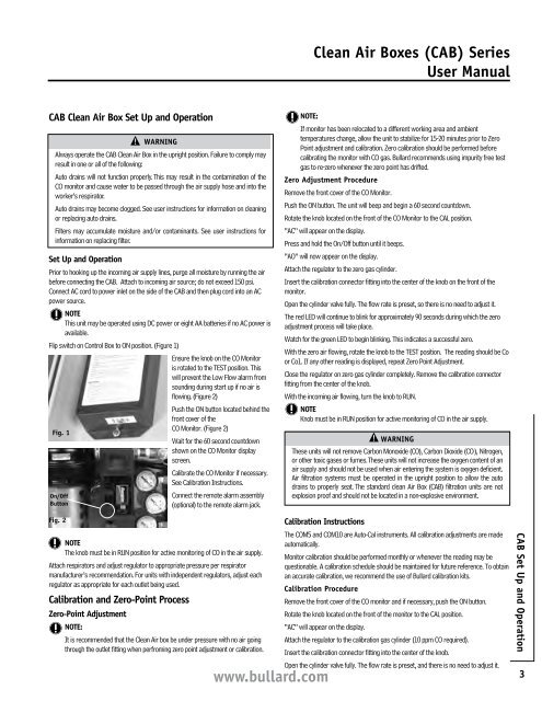
Flip switch on Control Box to ON position. (Figure 1)<br />
Ensure the knob on the CO Monitor<br />
is rotated to the TEST position. This<br />
will prevent the Low Flow alarm from<br />
sounding during start up if no air is<br />
flowing. (Figure 2)<br />
Push the ON button located behind the<br />
front cover of the<br />
CO Monitor. (Figure 2)<br />
Fig. 1<br />
Wait for the 60 second countdown<br />
shown on the CO Monitor display<br />
screen.<br />
Calibrate the CO Monitor if necessary.<br />
See Calibration Instructions.<br />
On/Off<br />
Button<br />
Fig. 2<br />
Connect the remote alarm assembly<br />
(optional) to the remote alarm jack.<br />
nOTE<br />
The knob must be in RUN position for active monitoring of CO in the air supply.<br />
Attach respirators and adjust regulator to appropriate pressure per respirator<br />
manufacturer’s re<strong>com</strong>mendation. For units with independent regulators, adjust each<br />
regulator as appropriate for each outlet being used.<br />
Calibration and Zero-Point Process<br />
Zero-Point Adjustment<br />
nOTE:<br />
It is re<strong>com</strong>mended that the <strong>Clean</strong> <strong>Air</strong> box be under pressure with no air going<br />
through the outlet fitting when perfroming zero point adjustment or calibration.<br />
<strong>www</strong>.<strong>bullard</strong>.<strong>com</strong><br />
<strong>Clean</strong> <strong>Air</strong> <strong>Boxes</strong> (<strong>CAB</strong>) <strong>Series</strong><br />
<strong>User</strong> <strong>Manual</strong><br />
nOTE:<br />
If monitor has been relocated to a different working area and ambient<br />
temperatures change, allow the unit to stabilize for 15-20 minutes prior to Zero<br />
Point adjustment and calibration. Zero calibration should be performed before<br />
calibrating the monitor with CO gas. Bullard re<strong>com</strong>mends using impurity free test<br />
gas to re-zero whenever the zero point has drifted.<br />
Zero Adjustment Procedure<br />
Remove the front cover of the CO Monitor.<br />
Push the ON button. The unit will beep and begin a 60 second countdown.<br />
Rotate the knob located on the front of the CO Monitor to the CAL position.<br />
“AC” will appear on the display.<br />
Press and hold the On/Off button until it beeps.<br />
“AO” will now appear on the display.<br />
Attach the regulator to the zero gas cylinder.<br />
Insert the calibration connector fitting into the center of the knob on the front of the<br />
monitor.<br />
Open the cylinder valve fully. The flow rate is preset, so there is no need to adjust it.<br />
The red LED will continue to blink for approximately 90 seconds during which the zero<br />
adjustment process will take place.<br />
Watch for the green LED to begin blinking. This indicates a successful zero.<br />
With the zero air flowing, rotate the knob to the TEST position. The reading should be Co<br />
or Co1. If any other reading is displayed, repeat Zero Point Adjustment.<br />
Close the regulator on zero gas cylinder <strong>com</strong>pletely. Remove the calibration connector<br />
fitting from the center of the knob.<br />
With the in<strong>com</strong>ing air flowing, turn the knob to RUN.<br />
nOTE<br />
Knob must be in RUN position for active monitoring of CO in the air supply.<br />
wArning<br />
These units will not remove Carbon Monoxide (CO), Carbon Dioxide (CO2), Nitrogen,<br />
or other toxic gases or fumes. These units will not increase the oxygen content of an<br />
air supply and should not be used when air entering the system is oxygen deficient.<br />
<strong>Air</strong> filtration systems must be operated in the upright position to allow the auto<br />
drains to properly seat. The standard clean <strong>Air</strong> Box (<strong>CAB</strong>) filtration units are not<br />
explosion proof and should not be located in a non-explosive environment.<br />
Calibration instructions<br />
The COM5 and COM10 are Auto-Cal instruments. All calibration adjustments are made<br />
automatically.<br />
Monitor calibration should be performed monthly or whenever the reading may be<br />
questionable. A calibration schedule should be maintained for future reference. To obtain<br />
an accurate calibration, we re<strong>com</strong>mend the use of Bullard calibration kits.<br />
Calibration Procedure<br />
Remove the front cover of the CO monitor and if necessary, push the ON button.<br />
Rotate the knob located on the front of the monitor to the CAL position.<br />
“AC” will appear on the display.<br />
Attach the regulator to the calibration gas cylinder (10 ppm CO required).<br />
Insert the calibration connector fitting into the center of the knob.<br />
Open the cylinder valve fully. The flow rate is preset, and there is no need to adjust it.<br />
<strong>CAB</strong> Set Up and Operation<br />
3