CA 300BC/Manual - Caliber Europe
CA 300BC/Manual - Caliber Europe
CA 300BC/Manual - Caliber Europe

Create successful ePaper yourself
Turn your PDF publications into a flip-book with our unique Google optimized e-Paper software.
E N G L I S H<br />
2<br />
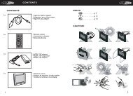
FEATURES<br />
•Bridgeable outputs.<br />
• Pulse Width Modulated (PWM) MOSFET Power Supply.<br />
• Thermal-, Overload- and Shortcircuit protection.<br />
•R<strong>CA</strong> in- and outputs.<br />
• Phase-control 0 - 180º<br />
• Adjustable input-level.<br />
•Variable low-pass control 40 - 160Hz.<br />
• Excellent muting circuitry assures no turn on/off ‘pops’.<br />
• Goldplated power connectors for optimal power distribution.<br />
• <strong>Europe</strong>an design and engineering.<br />
• Goldplated speaker connectors for optimal signal output.<br />
MOUNTING<br />
The amplifier should be protected from exposure to moisture and direct sunlight.<br />
Mark the mounting surface using the amplifier as a template, then drill 2.5mm (1/8”) diameter holes<br />
at the marked locations and mount the amplifier using the supplied self-tapping screws.<br />
INSTALLATION<br />
Remember to always disconnect battery ground before working on a vehicle’s electrical system!<br />
Always place a fuse or circuit breaker no more than 30cm (12”) from the battery, no greater than<br />
the fuse(s) of your amplifier for optimal protection.<br />
GETTING YOUR POWER STARTED<br />
• First, the +12V terminal is connected directly to the battery of your car. Use a cable of at least 10<br />
mm 2 (8 AWG), and make sure that the connectors are of the same value.<br />
- Don’t forget the extra “Vehicle protection” fuse.<br />
- The 12V + terminal should NOT be connected to the car fuse box.<br />
• Second, the ground terminal (GND) must be fastened securely to the chassis of the vehicle with the<br />
same gauge cable as the positive cable (the same amount of power has to run through it). Ensure<br />
that all paint, undercoating or any other insulation is removed from the area where you want to<br />
make your ground connection to.<br />
• Third, the last cable to connect is your remote turn-on (REM). Many radio-cassette and CD-players<br />
have an output terminal for connection of the REM of an amplifier. If you don’t have such an output,<br />
a separate switch must be installed to control your amplifiers on/off function.<br />
R<strong>CA</strong> INPUT<br />
• Connect the R<strong>CA</strong>-outputs of your radio to the R<strong>CA</strong> input terminals of the amplifier.Take good care<br />
that you connect the Right output of your radio to a Right input of your amplifier, and that you connect<br />
the Left output of your radio to a Left input of your amplifier.<br />
AMPLIFIER ADJUSTMENTS<br />
• Put the input level adjustment knob to the minimum.<br />
• Put the volume of your radio to 3/4 of the maximum.<br />
• Now adjust the input level. Slowly turn up the input level and listen carefully untill you hear the<br />
amplifier begin to distort. A <strong>Caliber</strong> Amplifier “clips” very softly, so this can sometimes be a difficult<br />
adjustment.You will hear that the Bass you wanted can be required in this way.<br />
<strong>CA</strong>LIBER WARRANTY<br />
Due to the complexity of our products, we strongly recommend that this amplifier is installed by<br />
your authorized <strong>Caliber</strong> dealer. If properly installed by your dealer we provide a warranty for 12<br />
month from the date of purchase.<br />
If you install this amplifier yourself, we wish you lots of fun and succes in doing so. If you follow our<br />
guidelines, you’ll get the best result. Our warranty, however, will be limited to and not exceed 30<br />
days from the date of purchase.<br />
E N G L I S H<br />
3<br />
4