CA 4050 - Caliber Europe
CA 4050 - Caliber Europe
CA 4050 - Caliber Europe

Create successful ePaper yourself
Turn your PDF publications into a flip-book with our unique Google optimized e-Paper software.
E n g l i s h<br />
2<br />
F E a t u R E s<br />
• Bridgeable outputs.<br />
• ’Tri-mode’ output capability, simultaneous stereo & bridged mono set up is possible.<br />
• Pulse Width Modulated (PWM) MOSFET Power Supply.<br />
• Variable input sensitivity: R<strong>CA</strong> input 0.5V to 2V.<br />
• Thermal-, Overload- and Shortcircuit protection.<br />
• Excellent muting circuitry assures no turn on/off ‘pops’.<br />
• Built-in High Pass / Full Range / Low Pass Filter Switch. 50Hz - 250Hz<br />
• Chrome plated power connectors for optimal power distribution.<br />
• <strong>Europe</strong>an design and engineering.<br />
• Chrome plated speaker connectors for optimal signal output.<br />
M O u n t i n g<br />
The amplifier has to have at least 5 cm (2”) ventilation space at all sides, to allow the heat to rise<br />
away from the amplifier. Be sure that the power and signal cables can enter and leave the amplifier<br />
in a straight line, to avoid the risk of malfunction. Always place the power- and signalcables at<br />
opposite sides of the vehicle to reduce any noises.<br />
The amplifier should be protected from exposure to moisture and direct sunlight.<br />
Mark the mounting surface using the amplifier as a template, then drill 2.5 mm (1/8”) diameter<br />
holes at the marked locations and mount the amplifier using the supplied self-tapping screws.<br />
i n s t a l l a t i O n<br />
Remember to always disconnect battery ground before working on a vehicle’s electrical system!<br />
Always place a fuse or circuit breaker no more than 30 cm (12”) from the battery, no greater<br />
than the fuse(s) of your amplifier for optimal protection.<br />
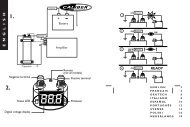
g E t t i n g y O u R P O w E R s t a R t E D<br />
• First, the +12V terminal is connected directly to the battery of your car. Use a cable of at<br />
least 10 mm 2 , and make sure that the connectors are of the same value.<br />
- Don’t forget the extra “Vehicle protection” fuse.<br />
- The 12V + terminal should NOT be connected to the car fuse box.<br />
• Second, the ground terminal (GND) must be fastened securely to the chassis of the vehicle with<br />
the same mm 2 cable as the positive cable (the same amount of power has to run through it).<br />
Ensure that all paint, undercoating or any other insulation is removed from the area where you<br />
want to make your ground connection to.<br />
• Third, the last cable to connect is your remote turn-on (REM). Many radio-cassette and<br />
CD-players have an output terminal for connection of the REM of an amplifier. If you don’t have<br />
such an output, a separate switch must be installed to control your amplifiers on/off function.