istruzioni per l'uso e manutenzione/ricambi instructions ... - Femi S.p.A.
istruzioni per l'uso e manutenzione/ricambi instructions ... - Femi S.p.A.
istruzioni per l'uso e manutenzione/ricambi instructions ... - Femi S.p.A.

You also want an ePaper? Increase the reach of your titles
YUMPU automatically turns print PDFs into web optimized ePapers that Google loves.
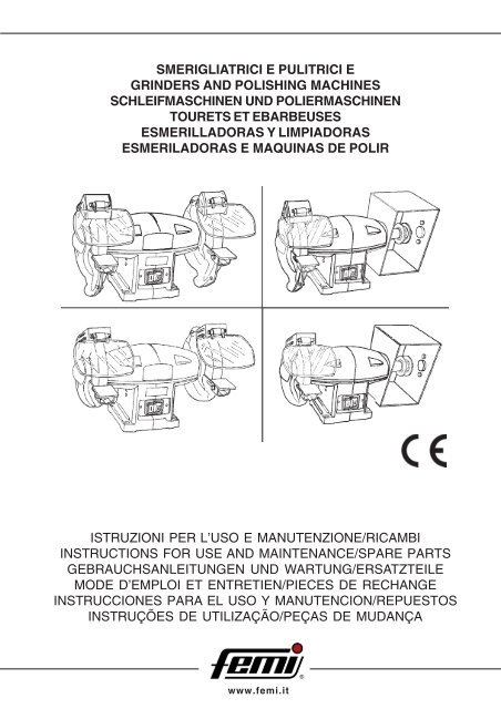
SMERIGLIATRICI E PULITRICI E<br />
GRINDERS AND POLISHING MACHINES<br />
SCHLEIFMASCHINEN UND POLIERMASCHINEN<br />
TOURETS ET EBARBEUSES<br />
ESMERILLADORAS Y LIMPIADORAS<br />
ESMERILADORAS E MAQUINAS DE POLIR<br />
ISTRUZIONI PER L’USO E MANUTENZIONE/RICAMBI<br />
INSTRUCTIONS FOR USE AND MAINTENANCE/SPARE PARTS<br />
GEBRAUCHSANLEITUNGEN UND WARTUNG/ERSATZTEILE<br />
MODE D’EMPLOI ET ENTRETIEN/PIECES DE RECHANGE<br />
INSTRUCCIONES PARA EL USO Y MANUTENCION/REPUESTOS<br />
INSTRUÇÕES DE UTILIZAÇÃO/PEÇAS DE MUDANÇA<br />
www.femi.it
DICHIARAZIONE DI CONFORMITÁ CE DEL COSTRUTTORE<br />
FEMI S.p.A.<br />
Via del Lavoro, 4 - 40023 Castel Guelfo (BO) - ITALIA<br />
Tel. +39-0542-670160 - Fax +39-0542-670185<br />
Dichiara che la: SMERIGLIATRICE<br />
è conforme alle disposizioni contenute nelle Direttive:<br />
CEE 98/37 - 89/336 - 73/23<br />
404<br />
405<br />
424<br />
425<br />
COMPLIANCE DECLARATION CE OF THE BUILDER<br />
FEMI S.p.A.<br />
Via del Lavoro, 4 - 40023 Castel Guelfo (BO) - ITALIA<br />
Tel. +39-0542-670160 - Fax +39-0542-670185<br />
Declare the: BENCH GRINDER<br />
is in compliance with the rules contents in the Directives:<br />
EEC 98/37 - 89/336 - 73/23<br />
CE KONFORMITATS ERKLARUNG DES HERSTELLER<br />
FEMI S.p.A.<br />
Via del Lavoro, 4 - 40023 Castel Guelfo (BO) - ITALIA<br />
Tel. +39-0542-670160 - Fax +39-0542-670185<br />
Erklart dass: SCHLEIFMASCHINE<br />
ist konform mit der Direktiven:<br />
EWG 98/37 - 89/336 - 73/23<br />
DECLARATION DE CONFORMITE CE DU CONSTRUCTEUR<br />
FEMI S.p.A.<br />
Via del Lavoro, 4 - 40023 Castel Guelfo (BO) - ITALIA<br />
Tel. +39-0542-670160 - Fax +39-0542-670185<br />
Declare que la: TOURET A MEULER<br />
est conforme aux disposition contenues dans les Directives:<br />
CEE 98/37 - 89/336 - 73/23<br />
DECLARATION DE CONFORMIDAD CE DEL CONSTRUCTOR<br />
FEMI S.p.A.<br />
Via del Lavoro, 4 - 40023 Castel Guelfo (BO) - ITALIA<br />
Tel. +39-0542-670160 - Fax +39-0542-670185<br />
Declara que la: SMERILLADORA<br />
esta conforme a las disposiciones contenide en la Directivas:<br />
CEE 98/37 - 89/336 - 73/23<br />
01 07<br />
02 08<br />
03 09<br />
04 10<br />
05 11<br />
06 12<br />
2007 2010<br />
2008 2011<br />
2009 2012<br />
DECLARAÇÃO DE CONFORMIDADE CE DO CONSTRUTTORE<br />
FEMI S.p.A.<br />
Via del Lavoro, 4 - 40023 Castel Guelfo (BO) - ITALIA<br />
Tel. +39-0542-670160 - Fax +39-0542-670185<br />
Declara que a: ESMERILADORA DE BANCADA<br />
suivindo as regras exigidas no contendo da Directivas:<br />
CEE 98/37 - 89/336 - 73/23<br />
1
INDICE/ INDEX / INHALT / INDEX / INDICE / ÍNDICE<br />
ITALIANO (IT) .................................................................................................................. 3 ÷ 7<br />
ENGLISH (EN) ................................................................................................................ 8 ÷ 12<br />
DEUTSCH (DE) ............................................................................................................ 13 ÷ 17<br />
FRANCAIS (FR) ........................................................................................................... 18 ÷ 22<br />
ESPANOL (ES) ............................................................................................................ 23 ÷ 27<br />
PORTUGUÊS (PT) ....................................................................................................... 28 ÷ 32<br />
2
INDICE<br />
1 INTRODUZIONE ALL’USO ..................................... 3<br />
2 INSTALLAZIONE ...................................................... 4<br />
3 REGOLAZIONI ........................................................ 5<br />
4 MANUTENZIONE ..................................................... 7<br />
1.2 SICUREZZA E NORMATIVA<br />
La macchina è progettata e costruita secondo le<br />
prescrizioni imposte dalle vigenti Direttive<br />
Comunitarie :<br />
CEE 98/37 - CEE 73/23 - CEE 89/336<br />
La dichiarazione di conformità CE allegata, unita al<br />
marchio CE posto sul prodotto, costituisce elemento<br />
fondamentale e parte integrante della macchina :<br />
garantiscono la conformità del prodotto alle Direttive<br />
di sicurezza sopra citate.<br />
IT<br />
1.3 TIPO DI IMPIEGO<br />
1 INTRODUZIONE<br />
Leggete attentamente queste <strong>istruzioni</strong> allo scopo<br />
di conoscere la macchina ed i suoi impieghi, e le<br />
eventuali controindicazioni.<br />
Conservate con cura questo manuale: esso fa<br />
parte integrante della macchina, e ad esso dovrete<br />
sempre riferirvi <strong>per</strong> eseguire al meglio e nelle<br />
massime condizioni di sicurezza le o<strong>per</strong>azioni che<br />
in esso sono descritte.<br />
Utilizzate la macchina solo ed esclusivamente <strong>per</strong><br />
gli impieghi di seguito specificati, usandola come<br />
raccomandato in questo manuale, e non cercando<br />
in alcun modo di manometterla o forzarla, o di usarla<br />
<strong>per</strong> scopi non adatti.<br />
1.1 SIMBOLOGIA<br />
Non sottovalutare i richiami “ATTENZIONE -<br />
CAUTELA” riportati in questo manuale.<br />
Al fine di attirare l’attenzione e dare messaggi di<br />
sicurezza le o<strong>per</strong>azioni <strong>per</strong>icolose sono precedute<br />
da simboli e note che ne evidenziano la <strong>per</strong>icolosità<br />
e spiegano come comportarsi <strong>per</strong> evitare il <strong>per</strong>icolo.<br />
Questi simboli e note sono di tre categorie<br />
identificate dalle parole:<br />
ATTENZIONE: comportamenti rischiosi che<br />
potrebbero provocare gravi lesioni.<br />
CAUTELA: comportamenti che potrebbero<br />
causare lesioni non gravi o danni alle cose.<br />
NOTE: le note precedute da questo simbolo<br />
sono di carattere tecnico e facilitano le<br />
o<strong>per</strong>azioni.<br />
Questa macchina è stata ideata e costruita <strong>per</strong><br />
o<strong>per</strong>azioni di asportazione di materiale, come<br />
smerigliatura o affilatura di utensili, su qualsiasi tipo<br />
di metallo.<br />
La versione combinata o pulitrice è dotata di<br />
sbraccio dell’albero rispettivamente su uno o due<br />
lati, atto ad accogliere spazzole di vario tipo (a filo<br />
di acciaio, a lamelle abrasive o di tessuto) <strong>per</strong> la<br />
pulitura ai vari livelli dei metalli di qualsiasi tipo.<br />
Evitate di usare la macchina <strong>per</strong> qualsiasi altro tipo<br />
di impiego che non sia previsto in queste <strong>istruzioni</strong>.<br />
1.4 NORME DI SICUREZZA<br />
- Non usate la macchina all’a<strong>per</strong>to, in luoghi molto<br />
umidi o con presenza di liquidi infiammabili o di<br />
gas.<br />
- Abbiate cura di posizionare la macchina in una<br />
zona di lavoro sufficientemente illuminata: ciò è<br />
di importanza fondamentale nella prevenzione<br />
degli infortuni.<br />
- Non forzate inutilmente la macchina: una<br />
pressione eccessiva può provocare un rapido<br />
deterioramento delle mole, un peggioramento<br />
delle prestazioni della macchina ed un dannoso<br />
surriscaldamento del motore.<br />
- Ogni volta che finite una o<strong>per</strong>azione, spegnete<br />
la macchina posizionando sullo “O” l’interruttore.<br />
- Evitate di indossare abiti con maniche larghe od<br />
oggetti, come sciarpe, catene o bracciali, che<br />
potrebbero essere agganciati dalle parti in<br />
movimento.<br />
- Usate sempre i dispositivi <strong>per</strong>sonali di protezione:<br />
occhiali antinfortunistici conformi alle norme,<br />
cuffie o inserti auricolari e cuffie <strong>per</strong> il<br />
contenimento dei capelli, se necessario.<br />
- Fate attenzione al cavo di alimentazione: non<br />
usatelo <strong>per</strong> sollevare la macchina o <strong>per</strong> staccare<br />
la spina dalla presa, e salvaguardatelo da spigoli<br />
vivi, oli e zone con elevate tem<strong>per</strong>ature.<br />
3
IT<br />
1.5 DESCRIZIONE DELLA MACCHINA<br />
- (Fig.1a: smerigliatrice)<br />
- (Fig.1b: smerigliatrice combinata)<br />
2 INSTALLAZIONE<br />
Posizionamento sul posto di lavoro (Fig. 2)<br />
1. CORPO MACCHINA<br />
2. INTERRUTTORE ON/OFF<br />
3. MOLA ABRASIVA<br />
4. PARASCINTILLE TRASPARENTE<br />
5. CUFFIA DI PROTEZIONE<br />
6. POGGIAPEZZI<br />
7. PARASCHEGGE REGOLABILE<br />
8. FORI PER IL FISSAGGIO<br />
9. PROTEZIONE SPAZZOLA<br />
10. SBRACCIO ALBERO<br />
1.6 RIMOZIONE DELL’IMBALLO,<br />
STOCCAGGIO E TRASPORTO<br />
Rimozione dell’imballo<br />
Togliete la macchina dall’imballo che la protegge<br />
durante il trasporto, avendo cura di conservare la<br />
scatola integra, nel caso dobbiate successivamente<br />
trasportarla da un posto di lavoro ad un altro, oppure<br />
se dovete immagazzinarla <strong>per</strong> lunghi <strong>per</strong>iodi.<br />
Movimentazione e trasporto<br />
Se la macchina è dotata di basamento, occorre<br />
prima separarla da questo, rimuovendo i dadi di<br />
fissaggio.<br />
ATTENZIONE: Le macchine con potenza<br />
su<strong>per</strong>iore o uguale a 1100 Watt, dato il<br />
loro rilevante peso, dovranno essere<br />
sollevate e posizionate nel posto di<br />
lavoro scelto, oppure trasportate da un<br />
posto di lavoro ad un altro, da almeno<br />
due <strong>per</strong>sone.<br />
Le macchine di potenza inferiore, dato il loro peso<br />
contenuto, possono essere sollevate e movimentate<br />
anche da una sola <strong>per</strong>sona.<br />
Stoccaggio<br />
Nel caso dobbiate immagazzinare la macchina, fate<br />
attenzione agli ideogrammi stampati sulla scatola,<br />
<strong>per</strong> evitare schiacciamenti della stessa <strong>per</strong><br />
sovraccarico o cadute <strong>per</strong> scarsa stabilita’ del<br />
carico.<br />
CAUTELA: Abbiate cura di posizionare<br />
la macchina in una zona di lavoro<br />
adeguata sia come condizioni<br />
ambiente che come luminosita’:<br />
ricordate sempre che le condizioni<br />
generali dell’ambiente di lavoro sono<br />
fondamentali nella prevenzione degli<br />
infortuni.<br />
Posizionate la macchina su un banco<br />
sufficientemente piano in modo da avere la migliore<br />
stabilità possibile. L’altezza ideale del banco deve<br />
essere quella che vi consente di posizionare il<br />
poggiapezzi 6 a circa un metro da terra.<br />
Fissaggio della macchina al banco di lavoro<br />
(Fig. 1a)<br />
Vi consigliamo di fissare la macchina al banco di<br />
lavoro, inserendo quattro viti M6 nei fori 8 e<br />
bloccandole dalla parte opposta con gli appositi<br />
dadi.<br />
Montaggio della macchina sul basamento<br />
(dove previsto)<br />
Per fissare la macchina al basamento utilizzare gli<br />
accessori in dotazione con lo stesso facendo<br />
corrispondere i fori 8 della macchina con i rispettivi<br />
fori sul piano su<strong>per</strong>iore di appoggio del basamento.<br />
Fissaggio del basamento a terra<br />
Se la macchina è fornita completa di basamento,<br />
oppure se il basamento viene fornito<br />
successivamente, è buona norma fissarlo al<br />
pavimento mediante gli appositi fori presenti sul<br />
piano di appoggio inferiore, e riempirlo di sabbia, in<br />
modo da rom<strong>per</strong>e eventuali vibrazioni e renderlo<br />
più stabile.<br />
Montaggio degli accessori (Fig. 1a-2)<br />
Prendete dal sacchetto contenuto nell’imballo i<br />
parascintille trasparenti 4, i paraschegge regolabili<br />
7 (dove presenti) e i poggiapezzi 6 ed assemblateli<br />
sulle cuffie di protezione 5 tramite le viti contenute<br />
nel sacchetto stesso,come mostrato in figura.<br />
4
2.1 COLLEGAMENTO ELETTRICO<br />
Messa a terra<br />
Accertatevi che l’impianto rete sul quale inserite la<br />
macchina sia collegato a terra come previsto dalle<br />
norme di sicurezza vigenti, e che la presa di<br />
corrente sia in buono stato.<br />
Montaggio della spina<br />
Collegate all’estremità del cavo rete della macchina<br />
una spina omologata secondo le normative di<br />
sicurezza, facendo attenzione ad inserire il<br />
conduttore di protezione giallo verde nell’apposito<br />
morsetto contrassegnato.<br />
Scelta della protezione magnetotermica<br />
Si ricorda all’utilizzatore che a monte dell’impianto<br />
rete deve sempre essere presente una protezione<br />
magnetotermica atta a salvaguardare tutti i<br />
conduttori dai cortocircuiti e dai sovraccarichi.<br />
Tale protezione dovrà essere scelta in base alle<br />
caratteristiche elettriche della macchina,<br />
specificate nella targhetta dei dati ad essa applicata.<br />
2.2 INFORMAZIONI RELATIVE AL RUMORE<br />
Le smerigliatrici determinano, nelle normali<br />
condizioni di utilizzo descritte in queste <strong>istruzioni</strong>,<br />
un livello equivalente di pressione acustica:<br />
Leq=60 dB(A) nel funzionamento a vuoto;<br />
Leq=77dB(A) durante le lavorazioni (es.<br />
smerigliatura di un tondino di<br />
acciaio C 40).<br />
Le rilevazioni sono state effettuate secondo le<br />
Norme UNI 7712, ISO 3740, ISO 3746, e CEE 89/<br />
392. E’ comunque raccomandato l’uso dei mezzi<br />
<strong>per</strong>sonali di protezione dell’udito, come cuffie o<br />
inserti auricolari.<br />
2.3 INFORMAZIONI SULLA COMPATIBILITÁ<br />
ELETTROMAGNETICA<br />
Le recenti Normative Europee sulla sicurezza, ed<br />
in particolare la Direttiva CEE 89/336, prescrivono<br />
che tutte le apparecchiature siano dotate di<br />
dispositivi di schermatura <strong>per</strong> i radiodisturbi sia da<br />
che verso l’ambiente esterno.<br />
Questa macchina è conforme alle prescrizioni.<br />
Le prove sono state eseguite secondo le Norme<br />
EN 55011, EN 55014, EN 50082-1, IEC 1000-4-2,<br />
IEC 1000-4-4.<br />
3 REGOLAZIONI (Fig. 2-3)<br />
Le normative antinfortunistiche internazionali<br />
prescrivono che il paraschegge regolabile 7 e il<br />
poggiapezzi 6 siano posizionati a non più di 2 mm.<br />
dal bordo <strong>per</strong>iferico della mola.<br />
Con il consumo la mola diminuisce di diametro, e<br />
queste distanze vengono incrementate.<br />
Controllate <strong>per</strong>iodicamente il loro valore e, se<br />
aumentato, riconducetelo nei limiti prescritti<br />
regolando gli accessori 7 ed 6 tramite le loro viti di<br />
fissaggio.<br />
3.1 UTILIZZO DELLA MOLA (Fig. 4-8)<br />
Inserite la spina del cavo di alimentazione nella<br />
presa di corrente dell’impianto rete.<br />
Mettete in funzione la macchina azionando il pulsante<br />
verde 12 dell’interruttore 2.<br />
ATTENZIONE: INDOSSATE SEMPRE GLI<br />
OCCHIALI DI PROTEZIONE .<br />
Mettete a contatto dolcemente il pezzo da lavorare<br />
con la mola , appoggiandolo al poggiapezzi 6, ed<br />
applicate uno sforzo progressivo, senza tuttavia<br />
premere eccessivamente, <strong>per</strong> evitare che la<br />
macchina <strong>per</strong>da il normale regime di giri.<br />
CAUTELA: Il pezzo da lavorare deve<br />
sempre essere tenuto con entrambe<br />
le mani, e di tanto in tanto raffreddato<br />
in una vaschetta con acqua.<br />
La mola di destra è di grana più grossa essa è più<br />
indicata <strong>per</strong> o<strong>per</strong>azioni di sgrossatura.<br />
La mola di sinistra è di grana più fine, ed è indicata<br />
maggiormente <strong>per</strong> finitura ed affilatura di utensili.<br />
Per fermare la macchina, premere il pulsante rosso<br />
13 dell’interruttore 2<br />
IT<br />
5
IT<br />
3.2 SOSTITUZIONE DELLA MOLA (Fig. 2-5-<br />
6)<br />
ATTENZIONE: prima di eseguire le<br />
o<strong>per</strong>azioni di <strong>manutenzione</strong>, sezionare<br />
l’alimentazione elettrica.<br />
Azionate l’interruttore 2 fermando la macchina, ed<br />
attendete che le mole abrasive siano <strong>per</strong>fettamente<br />
ferme.<br />
Smontate gli accessori 7 ed 6.<br />
Rimuovete il co<strong>per</strong>chio 14 della cuffia di protezione,<br />
svitando le relative viti.<br />
Con una chiave a<strong>per</strong>ta, svitate il dado 15, usando<br />
una chiave esagonale inserita nella sede ricavata<br />
all’ estremità dell’albero <strong>per</strong> tenere fermo lo stesso.<br />
Tenete presente che dal lato sinistro il dado ha<br />
filettatura sinistrorsa, quindi si svita in senso orario.<br />
Sostituite la mola usurata con una nuova.<br />
Controllo dell’integrita’ di una mola nuova<br />
Prima di montare la mola nuova, è bene sottoporla<br />
ad una prova del suono onde verificarne l’integrità.<br />
Per effettuare questa prova, le mole dovranno<br />
essere asciutte e pulite, altrimenti il suono emesso<br />
potrebbe risultare smorzato.<br />
Con l’aiuto di uno strumento non metallico (manico<br />
in legno di un cacciavite oppure mazzuolo in legno)<br />
battete leggermente la mola sulla parte laterale (Fig.<br />
5): un leggero colpo su una mola integra dà un<br />
suono pulito e gradevole.<br />
Se il suono emesso è invece sordo o incrinato, la<br />
mola non dovrà essere utilizzata.<br />
Riavvitate il dado 15 (Fig. 6).<br />
Rimontate il co<strong>per</strong>chio 14 della cuffia di protezione.<br />
Riassemblate gli accessori smontati in precedenza.<br />
Se il movimento radiale ed assiale della mola in<br />
rotazione, misurati rispettivamente sulla<br />
circonferenza e sulla parete laterale della mola,<br />
risulta troppo elevato, la mola produce vibrazioni<br />
eccessive durante l’uso al massimo regime di<br />
rotazione.<br />
Per diminuire tale valore, arrestate la macchina,<br />
allentate la mola e ruotatela di un quarto di giro sul<br />
proprio asse tenendo fermo l’albero motore, poi<br />
ribloccatela; se non dovesse modificarsi alcunchè,<br />
ripetete l’o<strong>per</strong>azione più volte fino a trovare la<br />
migliore posizione possibile.<br />
3.3 UTILIZZO DELLA SPAZZOLA (Fig. 7)<br />
La parte destra della smerigliatrice combinata è<br />
costruita in modo da potere alloggiare una spazzola<br />
<strong>per</strong> la pulitura o lucidatura di metalli di vario tipo.<br />
Possono essere montate spazzole a filamento<br />
metallico (pulitura) oppure spazzole di panno o<br />
tessuto (lucidatura) con diametro massimo,<br />
larghezza massima e foro del collare di tenuta<br />
variabili a secondo del modello (vedi tabella<br />
“IMPIEGO DEGLI UTENSILI APPROPRIATI”).<br />
Controllate sempre che il diametro del collare<br />
centrale 16 che tiene insieme i filamenti sia maggiore<br />
del diametro delle flange di fissaggio 17presenti<br />
sulla macchina.<br />
ATTENZIONE: E’ vietato fissare le<br />
spazzole con le flange direttamente in<br />
presa sui filamenti.<br />
Controllate di tanto in tanto lo stato generale della<br />
spazzola mediante esame a vista, soprattutto <strong>per</strong><br />
quanto concerne la tenuta dei filamenti tramite il<br />
collare centrale : se doveste verificare che il collare<br />
non chiude più bene, non esitate a sostituire la<br />
spazzola con una nuova.<br />
ATTENZIONE: prima di eseguire le<br />
o<strong>per</strong>azioni di <strong>manutenzione</strong>, sezionare<br />
l’alimentazione elettrica.<br />
Montaggio della spazzola<br />
Assicuratevi che la macchina sia spenta e che gli<br />
utensili già presenti (es.mole) siano <strong>per</strong>fettamente<br />
fermi.<br />
Svitate con chiave esagonale il dado 18 che serra<br />
le flange sull’albero.<br />
Estraete la flangia di serraggio 17 dalla sua sede.<br />
Inserite la spazzola sull’albero, controllando che il<br />
foro della stessa sia uguale al diametro dell’albero<br />
o della boccola di riduzione in dotazione su cui va<br />
fissata.<br />
Riposizionate la flangia di serraggio 17 sull’albero<br />
mettendola a contatto con il collare della spazzola<br />
16.<br />
Togliete il tappo laterale centrale 19 dalla protezione,<br />
ed introducete dal foro una chiave a brugola fino<br />
all’inserimento nella sede sull’albero 20.<br />
A questo punto, tenendo bloccato l’albero con al<br />
chiave a brugola, serrate il dado di fissaggio sulle<br />
flange.<br />
Provate a ruotare a mano la spazzola <strong>per</strong> verificare<br />
la sua centratura; nel caso dovesse essere<br />
difettosa, provvedete a ripetere le fasi sopra<br />
descritte.<br />
6
IMPIEGO DEGLI UTENSILI APPROPRIATI<br />
ARTICOLO<br />
404<br />
424<br />
405<br />
425<br />
mm.<br />
150x20x16<br />
150x20x16<br />
200x20x16<br />
200x20x16<br />
mm<br />
/<br />
150x25x16<br />
/<br />
150x25x16<br />
3.4 ASPIRAZIONE E RACCOLTA DELLE<br />
POLVERI<br />
La macchina è dotata di bocche <strong>per</strong> lo scarico delle<br />
polveri sia nelle cuffie di protezione delle mole<br />
(smerigliatrici) che nelle protezioni spazzola<br />
(combinate e pulitrici) e nastro abrasivo.<br />
E’ quindi possibile dotarla di impianto di aspirazione<br />
delle polveri, richiedendo al vostro rivenditore di<br />
fiducia l’aspiratore completo di accessori di<br />
collegamento e di sacco raccoglipolvere, <strong>per</strong><br />
mantenere la salubrità e la pulizia nell’ambiente di<br />
lavoro.<br />
4.1 SMALTIMENTO MACCHINA,<br />
IMBALLAGGIO<br />
Quando si rende necessario,<br />
alla fine del normale ciclo di<br />
funzionamento, rottamare la<br />
macchina, essa dovrà essere<br />
conferita ad un Centro di<br />
raccolta e smaltimento dei rifiuti<br />
autorizzato al fine di rispettare<br />
le Norme <strong>per</strong> l’igiene e la<br />
2002/96/EC<br />
salvaguardia dell’ambiente.<br />
Anche l’imballaggio va smaltito secondo le normative<br />
vigenti, conferendolo a soggetti autorizzati alla<br />
raccolta ed allo smaltimento o al recu<strong>per</strong>o.<br />
Rivolgetevi quindi al CONSORZIO DEGLI OLI USATI<br />
PIU’ VICINO.<br />
IT<br />
4 MANUTENZIONE<br />
Le normali o<strong>per</strong>azioni di <strong>manutenzione</strong> ordinaria,<br />
effettuabili anche da <strong>per</strong>sonale non specializzato,<br />
sono tutte descritte nei paragrafi precedenti e nel<br />
presente.<br />
Nel caso sia necessario l’intervento di <strong>per</strong>sonale<br />
qualificato <strong>per</strong> o<strong>per</strong>azioni di <strong>manutenzione</strong><br />
straordinaria, oppure in caso di riparazioni, sia in<br />
regime di garanzia che successivamente,<br />
rivolgetevi sempre ad un centro di assistenza<br />
autorizzato, oppure direttamente alla fabbrica, se<br />
nella vostra regione non è presente il centro di<br />
assistenza.<br />
7
EN<br />
INDEX<br />
1 INTRODUCTION TO USE ..................................... 10<br />
2 INSTALLATION ....................................................... 11<br />
3 ADJUSTMENT ........................................................ 12<br />
4 MAINTENANCE ...................................................... 14<br />
1.2 STANDARDS ON SAFETY<br />
The machine has been designed and manufactured<br />
conforming to the norms set forth by the following<br />
prevailing Machinery Directives: EEC 98/37 - EEC<br />
73/23 - EEC 89/336<br />
The annexed CE Declaration of Conformity, together<br />
with the CE mark attached to the product, constitute<br />
an essential element and are an integral part of the<br />
machine: they guarantee that the product duly<br />
conforms to the aforesaid safety Directives.<br />
1.3 TYPE OF USE<br />
1 INTRODUCTION<br />
Please read these <strong>instructions</strong> carefully in order to<br />
learn how to use this machine and how to deal<br />
with any contraindications. Keep these <strong>instructions</strong><br />
in a safe place: they are an integrating part of the<br />
machine. This instruction manual is an integral part<br />
of the machine and therefore must be kept complete<br />
and handled with care. Always refer to the<br />
contents reported in this manual for carrying out all<br />
the o<strong>per</strong>ations required for using the machine to<br />
the best advantage and under utmost safety<br />
conditions.<br />
Use the machine solely and exclusively for the uses<br />
outlined below, as recommended in this manual,<br />
and do not attempt to tam<strong>per</strong> with it, force it or use<br />
it for other purposes.<br />
1.1 CONVENTIONAL SYMBOLS<br />
Never underestimate the warnings "ATTENTION -<br />
CAUTION" given in this manual.<br />
In order to draw the user's attention and to preserve<br />
safety, hazardous o<strong>per</strong>ation are preceded by<br />
symbols and notes that point out the danger and<br />
explain how to behave to avoid any risk.<br />
These symbols and notes are divided in three<br />
categories, identified by the following words:<br />
WARNING: dangerous-behaviours that<br />
could cause serious injuries.<br />
CAUTION: behaviours that could cause<br />
slight injuries or damages to things.<br />
NOTE: the notes preceded by this symbols<br />
are technical and are aimed at making<br />
o<strong>per</strong>ations easier.<br />
This machine has been conceived and<br />
manufactured to remove material, such as tool<br />
grindings or lappings, from any type of metal.<br />
In the bench grinder and polishing machine<br />
(combined version) the shaft is fitted with an<br />
extension on one or both sides, where it is possible<br />
to fit several types of brushes (such as with steel<br />
wires, with abrasive blades or in fabric) suitable<br />
for any type of metal. Avoid using it for any other<br />
type of use that is not foreseen by these<br />
<strong>instructions</strong>.<br />
1.4 SAFETY REGULATIONS<br />
- Do not use the machine outdoors, in humid places<br />
or in the presence of gas or flammable liquids.<br />
- Put the machine in a well lit working area: this is<br />
extremely important in preventing work<br />
accidents.<br />
- Do not force the machine unnecessarily:<br />
excessive pressure could cause the grinding<br />
wheel to deteriorate very quickly, the machine’s<br />
<strong>per</strong>formances could worsen and the motor be<br />
damaged by overheating.<br />
- Each time a machine o<strong>per</strong>ation is finished, turn<br />
off the machine switching it to position “O”.<br />
- Avoid wearing loose-sleeved work clothes or<br />
accessories such as scarves, neck-chains or<br />
bracelets which could be hooked by the moving<br />
parts.<br />
- Always use protection devices: accident<br />
prevention eyeglasses as foreseen by<br />
regulations, headsets or earphones and if<br />
necessary, caps to hold back loose hair.<br />
- Do not use the electric feeding cable to lift the<br />
machine or to take off the plug from the current<br />
tap. Avoid contact with sharp edges, oils and<br />
high tem<strong>per</strong>atures.<br />
8
1.5 DESCRIPTION OF THE MACHINE<br />
- (Picture 1a: bench grinder)<br />
- (Picture 1b: combined bench grinder)<br />
2 INSTALLATION<br />
Positioning in working area (Picture 2)<br />
1. MACHINE BODY<br />
2. TURNING-ON SWITCH<br />
3. ABRASIVE GRINDING WHEEL<br />
4. TRANSPARENT SPARK ARRESTERS<br />
5. SAFETY CAP<br />
6. PIECE-REST<br />
7. ADJUSTABLE CHIP GUARDS<br />
8. KEEPER HOLES<br />
9. BRUSH PROTECTION<br />
10 . SHAFT EXTENSION<br />
1.6 PACKING REMOVAL, STORAGE and<br />
TRANSPORT<br />
Packing removal<br />
If the machine is fit with a base, first separate it<br />
from the machine by removing the fastening screw<br />
nuts.<br />
Remove the machine from the packing that protects<br />
it during transport. Please do not throw the box<br />
away, it could be useful in case you will have to<br />
displace the machine or need to store it for long<br />
<strong>per</strong>iods.<br />
Displacement and transport<br />
WARNING: The machines with more<br />
than 1100 Watt are very heavy and must<br />
therefore be lifted and positioned on<br />
the choosen working place.<br />
Otherwise they have to be displaced<br />
by at least two people.<br />
CAUTION: Ensure that the machine is<br />
located in a suitable area both as far<br />
as work environment and lighting are<br />
concerned: always keep in mind that<br />
the overall work environment<br />
conditions are essential for preventing<br />
accidents.<br />
Position the machine on a sufficiently flat bench<br />
so as to have the best stability possible.<br />
The ideal height of the bench is that allowing the<br />
positioning of the piece-rest 6 at about one meter<br />
from the ground.<br />
Machine fastening on working table (Picture<br />
1a)<br />
We recommend to secure the machine to the work<br />
bench, by inserting four M6 screws in holes 8,<br />
locking them on the opposite side using the<br />
appropriate screw nuts.<br />
Machine fastening on the column (where<br />
foreseen)<br />
In order to secure the machine to the base, use<br />
the standard fittings provided. Match holes 8 of<br />
the machine with the corresponding holes in the<br />
up<strong>per</strong> support surface of the base.<br />
Securing the base to the floor<br />
The column (if delivered with the machine) has to<br />
be fixed to the floor through the special holes on<br />
its lower part. Furthermore fill it with sand to avoid<br />
vibrations and in order to increase its stability.<br />
EN<br />
Machines with a lower power can be lifted and<br />
displaced by one <strong>per</strong>son only.<br />
Storage<br />
Should you have to store the machine, please take<br />
into account the ideograms printed on the box. Do<br />
not crush the box with overloads and put it in a<br />
safe position so that it does not fall.<br />
Fitting of auxiliary equipment<br />
From the bag inside the packaging take out the<br />
adjustable chip guards 7, the transparent spark<br />
arresters 4 and the piece-rests 6 and assemble<br />
them onto the safety caps 5 using the screws<br />
inside the same bag, as shown in picture.<br />
9
EN<br />
2.1 ELECTRIC CONNECTION<br />
Grounding<br />
Check that the power grid to which the machine is<br />
plugged in is grounded as foreseen by the safety<br />
rules in force, and that the current socket is in<br />
good condition.<br />
Plug fitting<br />
Connect a plug in compliance with safety regulation<br />
to the end of the mains cable of the machine, check<br />
that the yellow/green protective conductor is fitted<br />
into the relative terminal.<br />
3 ADJUSTMENTS (Picture 2-3)<br />
The international safety rules prescribe that the<br />
adjustable chip guards 7 and the piece-rest 6 are<br />
to be positioned not more than 2 mm. from the<br />
<strong>per</strong>ipheral edge of the grinding wheel.<br />
As the grinding wheel wears out, its diameter<br />
decreases, and these distances are then<br />
increased.<br />
Periodically check their values and, if they have<br />
increased, reduce them within the fixed limits by<br />
adjusting accessories 7 and 6 by means of their<br />
fastening screws.<br />
Choice of the thermal protection<br />
We remind the user that a magnetothermic<br />
protection, fit for safeguarding all the conductors<br />
from short-circuits and overloads, must always<br />
be placed before the power grid.<br />
Said protection is to be chosen according to the<br />
electric specifications of the machine, indicated<br />
on the data plate applied to it.<br />
2.2 NOISE RELATED INFORMATION<br />
Under normal working conditions as described in<br />
these <strong>instructions</strong>, the grinding machines bring<br />
about a level of acoustic pressure corresponding<br />
to:<br />
Leq = 60 dB (A) when idling;<br />
Leq = 77 dB (A) during workings (for example:<br />
lapping a C 40 steel rod)<br />
Tests were carried out according to UNI 7712,<br />
ISO 3740, ISO 3746 and CEE 89/392 regulation.<br />
It is however recommended to use <strong>per</strong>sonal means<br />
for hearing protection, such as headsets or<br />
earphones.<br />
2.3 ELECTROMAGNETIC COMPATIBILITY<br />
INFORMATION<br />
The recent European Safety Standards, especially<br />
EEC Directive 89/336, set forth that all the<br />
equipment must be fit with radio interference<br />
suppressors both to and from the outside<br />
environment.<br />
This machine conforms to such Standards.<br />
Tests were carried out according to EN 55011, EN<br />
55014, EN 50082-1, IEC 1000-4-2, IEC 1000-4-4<br />
regulations.<br />
3.1 USE OF THE GRINDING WHEEL (Picture<br />
4-8)<br />
Insert the input cable plug into the current socket<br />
of the power grid.<br />
Start running the machine by pressing the green<br />
pushbutton 12 of switch 2.<br />
WARNING: ALWAYS WEAR ACCIDENT<br />
PREVENTION EYEGLASSES.<br />
Gently bring the piece to be worked in contact<br />
with the grinding wheel, laying it on piece-rest 6,<br />
and start applying pressure progressively, but<br />
without pushing too hard, so that the machine will<br />
not lose the normal r.p.m.<br />
CAUTION: The piece being worked on<br />
must always be held with both hands,<br />
and cooled every now in a tank of<br />
water.<br />
The grinding wheel on the right is of a thicker grain:<br />
it is more suitable for chipping o<strong>per</strong>ations.<br />
The left grinding wheel is of a thinner grain, and is<br />
more suitable for finishing and grinding tools.<br />
In order to stop the machine, press the red<br />
pushbutton 13 of switch 2 or press the emergency<br />
stop button 11.<br />
10
3.2 REPLACING THE GRINDING WHEEL<br />
(pictures 2-5-6)<br />
WARNING: Prior to <strong>per</strong>forming any<br />
maintenance o<strong>per</strong>ation, disconnect the<br />
electric power supply.<br />
Activate switch 2 to stop the machine and wait<br />
until the grinding wheels have stopped completely.<br />
Take away parts 7 and 6.<br />
Remove cover 14 from the safety cap, unscrewing<br />
the relevant screws.<br />
With an open key unscrew the nut 15 and keep the<br />
shaft steady through an hexagonal key, keeping in<br />
mind that on the left side it has a left-handed<br />
threading, and therefore it is unscrewed in<br />
clockwise direction.<br />
Replace worn out grinding wheel with a new one.<br />
3.3 USE OF THE BRUSH (Fig. 7)<br />
The right-hand part of the combined bench grinder<br />
is manufactured so that it can house a brush for<br />
the cleaning or polishing of various types of metals.<br />
It is possible to fit metal wire brushes (cleaning) or<br />
cloth/fabric brushes (polishing) with varying<br />
maximum diameter, maximum width and stop collar<br />
hole, depending on the model (refer to the “USE OF<br />
APPROPRIATE TOOLINGS” table).<br />
Ensure that the diameter of the middle collar 16 that<br />
keeps the wires together is always greater than<br />
the diameter of the fastening flanges 17 provided<br />
on the machine.<br />
WARNING: It is prohibited to secure the<br />
brushes with the flanges in direct<br />
contact with the wires.<br />
EN<br />
Check if a new grinding wheel is integral<br />
Before mounting the new grinding wheel, it is<br />
advisable to <strong>per</strong>form a sound test in order to check<br />
its integrity.<br />
To carry out this test, the grinding wheels must be<br />
dry and clean, otherwise the emitted sound could<br />
result dampened. With the help of a non-metallic<br />
tool (wooden handle of a screwdriver or a wooden<br />
mallet), lightly strike the grinding wheel on its side<br />
(picture 5): a light strike against an integral grinding<br />
wheel produces a pleasant and clear sound.<br />
If, on the other hand, the emitted sound is dull or<br />
cracked, the grinding wheel should not be used.<br />
Retighten 15 screw nut.<br />
Reassemble cover 14 of the safety cap.<br />
Re-assemble the pieces that were taken off<br />
previously.<br />
If the radial and axial movement of the rotating<br />
grinding wheel, gauged both on the circumference<br />
and on the side wall of the grinding wheel<br />
respectively, should be too much, the grinding wheel<br />
produces excessive vibration when used at<br />
maximum rotating capacity.<br />
In order to decrease such value, stop the machine,<br />
loosen the grinding wheel and turn it on its axis by<br />
1/4 turn holding the motor shaft firmly, then lock the<br />
grinding wheel. If the problem <strong>per</strong>sists, repeat the<br />
o<strong>per</strong>ation as many times as required until the best<br />
possible position is found.<br />
Every now and then check the general condition of<br />
the brush by visually inspecting it, especially as<br />
concerns the hold of the wires, by means of the<br />
middle collar. If you notice that the collar does not<br />
close <strong>per</strong>fectly any more, replace the brush with a<br />
new one at once.<br />
WARNING: Prior to <strong>per</strong>forming any<br />
maintenance o<strong>per</strong>ation, disconnect the<br />
electric power supply.<br />
Fitting of the brush<br />
Ensure that the machine is OFF and that the toolings<br />
provided (e.g. grinding wheels) are <strong>per</strong>fectly still.<br />
Use an Allen wrench to unscrew the screw nut 18<br />
that locks the flanges to the shaft.<br />
Remove the tightening flange 17 from its seat.<br />
Fit the brush onto the shaft, ensuring that the hole<br />
of the brush has the same diameter of the shaft or<br />
of the adapting bush provided onto which it is<br />
secured.<br />
Re-position the tightening flange 17 onto the shaft<br />
making it touch the collar 16 of the brush.<br />
Remove the middle side plug 19 from the protection<br />
and introduce a socket wrench through the hole<br />
until the seat is pro<strong>per</strong>ly fit on the shaft 20.<br />
At this point, keeping the shaft locked by means of<br />
the socket wrench, tighten the fastening screw<br />
nut on the flanges.<br />
Try to turn the brush by hand to make sure that it is<br />
centered. If it does not turn pro<strong>per</strong>ly, repeat the<br />
aforesaid steps.<br />
11
EN<br />
USE OF APPROPRIATE TOOLINGS<br />
ITEM<br />
404<br />
424<br />
405<br />
425<br />
mm.<br />
150x20x16<br />
150x20x16<br />
200x20x16<br />
200x20x16<br />
mm<br />
/<br />
150x25x16<br />
/<br />
150x25x16<br />
4.1 DISPOSAL OF THE MACHINE, PACKING<br />
At the end of the machine life, if<br />
the machine must be scraped,<br />
contact an authorised waste<br />
disposal centre in order to comply<br />
with the Standards for hygiene<br />
and environment safeguard.<br />
The packing must be disposed<br />
of according to the ruling<br />
2002/96/EC<br />
standards by delivering it to authorised people for<br />
the collection, disposal or reclaim.<br />
Please contact the ASSOCIATION OF USED OILS<br />
near to you.<br />
3.4 SUCTION AND POWDERS COLLECTION<br />
The machine is fitted with holes for discharging<br />
the powders both from the wheels protection<br />
caps (bench-grinders) and from the brush<br />
protection (combined versions and polishing<br />
machines).<br />
It is possible to fit it with a powders suction system.<br />
Ask your dealer the complete suction unit with all<br />
connections and the bags for powders collection<br />
in order to keep the working area clean and<br />
salubrious.<br />
4 MAINTENANCE<br />
Normal o<strong>per</strong>ations of routine maintenance, which<br />
can be also be carried out by non-skilled<br />
<strong>per</strong>sonnel, are all described in the previous<br />
paragraphs and in the present one.<br />
In case the intervention of qualified <strong>per</strong>sonnel is<br />
required for extraordinary maintenance o<strong>per</strong>ations,<br />
or in case of repairs, both during guarantee <strong>per</strong>iods<br />
and afterwards, always turn to an authorized<br />
service center, or directly to the factory if the<br />
service center is not present in your area.<br />
12
INHALT<br />
1 EINFÜHRUNG .................................................... 15<br />
2 INSTALLIEREN ................................................... 16<br />
3 EINSTELLUNGEN .............................................. 17<br />
4 WARTUNG ........................................................... 19<br />
1.2 SICHERHEIT UND NORMWERKE<br />
Die Entwicklung und die Herstellung der Maschine<br />
erfolgte gemäß der Vorschriften der geltenden<br />
gemeinschaftlichen Richtlinien:<br />
98/37/EWG - 73/23/EWG - 89/336/EWG<br />
Die beigelegte Konformitätsbescheinigung CE stellt<br />
gemeinsam mit der auf dem Produkt angebrachten<br />
CE-Kennzeichung einen wesentlichen Bestandteil<br />
der Maschine dar: dadurch wird die Übereinstimmung<br />
des Produktes mit den oben aufgeführten<br />
Sicherheitsrichtlinien garantiert.<br />
DE<br />
1 EINLEITUNG<br />
Lesen Sie sorgfältig diese Gebrauchsanweisung<br />
durch, damit Sie die Maschine und ihre<br />
Anwendungsbereiche kennenlernen, sowie die<br />
eventuellen Vorsichtsmassnahmen.<br />
Die Gebrauchsanweisung sorgfältig aufbewahren:<br />
sie ist ein wesentlicher Teil der Maschine.Bewahren<br />
Sie das vorliegende Handbuch sorgfältig auf: es<br />
stellt einen wesentlichen Bestandteil der Maschine<br />
dar und Sie sollten stets auf seine Inhalte Bezug<br />
nehmen, um die darin beschriebenen<br />
Arbeitsvorgänge ordentlich und unter umfassender<br />
Beachtung der Sicherheitsanforderungen<br />
auszuführen.<br />
Verwenden Sie die Maschine ausschließlich für die<br />
nachfolgend angegebenen Einsätze, betreiben Sie<br />
diese entsprechend der im vorliegenden Handbuch<br />
aufgeführten Empfehlungen. Veränderungen oder<br />
Gewaltanwendung sowie unsachgemäßer<br />
Gebrauch sollten dringend unterbleiben.<br />
1.1 PIKTOGRAMME<br />
Bitte die Anweisungen "ACHTUNG - VORSICHT -<br />
ANMERKUNG" im Handbuch nicht unterschätzen.<br />
Um Ihre Aufmerksamkeit zu wecken und um<br />
Sicherheitssignale zu geben, erscheinen bei<br />
gefährlichen Arbeiten, Symbole und Anmerkungen,<br />
die das Risiko bei der Arbeit hervorheben und<br />
zugleich erklären, wie sich man verhalten muss,<br />
um Gefahren zu vermeiden. Es handelt sich um<br />
drei Symbole, die durch folgende Wörter<br />
gekennzeichnet werden:<br />
ACHTUNG: Gefährliches Verhalten, das zu<br />
schweren Verletztungen führen kann.<br />
VORSICHT: Verhalten, das zu Verletzungen<br />
oder Schäden an Gegenständen führen<br />
kann.<br />
MERKE: Anmerkungen mit diesem Symbol,<br />
betreffen technische Hilfen, die die Arbeit<br />
erleichtern können.<br />
1.3 ANWENDUNGSBEREICHE<br />
Diese Maschine ist entwickelt und konstruiert<br />
worden, um Materialabtragungsarbeiten, wie<br />
Schleifen oder Schärfen von Werkzeugen an<br />
jeglichem Metall durchzuführen.<br />
Bei der Schleif- und Poliermaschine (kombinierter<br />
Version) hat die Welle eine Verlängerung an einer<br />
oder an beiden Seiten. Bürsten verschiedener Art<br />
(mit Stahldraht, mit Schleiflamellen oder Gewebe)<br />
können hier verwendet werden zum Polieren aller<br />
Metalle.<br />
Vermeiden Sie, die Maschine für jeglichen anderen<br />
Gebrauch als den in dieser Gebrauchsanweisung<br />
vorgesehen zu benützen.<br />
1.4 SICHERHEITSVORSCHRIFTEN<br />
- Die Maschine nicht im Freien, in sehr feuchten<br />
Plätzen oder in Anwesenheit feuergefährlicher<br />
Flüssigkeiten oder Gas benützen.<br />
- Die Maschine in einer Arbeitszone aufstellen,<br />
wo ausreichend Licht vorhanden ist: dies ist von<br />
grundlegender Wichtigkeit hinsichtlich der<br />
Unfallverhütung.<br />
- Die Maschine nicht unnötig beanspruchen: ein<br />
übermäßiger Druck kann zu einem schnellen<br />
Verschleiss der Schleifscheiben, einer<br />
Verschlechterung der Maschinenleistung und<br />
einem schädlichen Heisslaufen des Motors<br />
führen.<br />
- Nach jeglicher Arbeit schalten Sie die Maschine<br />
aus, indem Sie den Schalter auf “O” stellen.<br />
- Vermeiden Sie das Tragen von Kleidungsstücken<br />
mit weiten Ärmeln oder Gegenständen wie Schale,<br />
Ketten oder Armbänder, die an laufenden Teilen<br />
der Maschine hängenbleiben könnten.<br />
- Benützen Sie stets die <strong>per</strong>sönlichen<br />
Schutzgegenstände: den Bestimmungen<br />
entsprechenden Schutzbrillen, Ohrenschützer<br />
oder Ohrenstöpsel und Hauben zum<br />
Zusammenhalten der Haare, falls notwendig.<br />
- Beachten Sie das Elektrokabel: heben Sie die<br />
Maschine nicht damit auf und ziehen Sie damit<br />
den Stecker nicht aus der Steckdose. Vermeiden<br />
Sie es mit scharfen Kanten oder Öle in Berührung<br />
zu bringen oder hohen Tem<strong>per</strong>aturen<br />
auszusetzten.<br />
13
1.5 BESCHREIBUNG DER MASCHINE<br />
2 MONTAGE<br />
DE<br />
- (Bild 1a: Schleifmaschine)<br />
- (Bild 1b: Schleif und -Poliermaschine)<br />
1. MASCHINENKÖRPER<br />
2. STARTSCHALTER<br />
3. SCHLEIFSCHEIBE<br />
4. DURCHSICHTIGER FUNKENSCHIRM<br />
5. SCHUTZHAUBE<br />
6-STÜCKAUFLAGEFLÄCHE<br />
7. REGULIERBARE SPLITTER-<br />
8. BEFESTIGUNGSBOHRUNGEN ABDECKUNG<br />
9. BÜRSTENSCHUTZ<br />
10. WELLENVERLÄNGERUNG<br />
Positionierung an der Arbeitszone (Bild 2)<br />
VORSICHT: Gehen Sie bei der<br />
Aufstellung der Maschine umsichtig<br />
vor: der Arbeitsbereich sollte sowohl<br />
im Hinblick auf die<br />
Umgebungsbedingungen als auch<br />
hinsichtlich der Beleuchtungsverhältnisse<br />
geeignet sein.<br />
Denken Sie stets daran, daß die<br />
allgemeinen Bedingungen im<br />
Arbeitsumfeld wesentliche Faktoren<br />
für die Unfallverhütung darstellen.<br />
1.6 ENTFERNEN DER VERPACKUNG,<br />
LAGERUNG UND TRANSPORT<br />
Entfernen der Verpackung<br />
Die Maschine aus der Verpackung herausnehmen.<br />
Bitte die Schachtel sorgfältig aufbewahren, sollten<br />
Sie die Maschine transportieren oder längere Zeit<br />
lagern wollen.<br />
Bewegung und Transport<br />
Ist die Maschine mit einem Untergestell ausgestattet,<br />
so muß sie erst von diesem abgenommen werden.<br />
Hierzu sollten die Befestigungsmuttern entfernt<br />
werden.<br />
ACHTUNG: Die Maschinen mit einer<br />
Leistung von mehr als 1100 Watt sind<br />
ziemlich schwer und müssen daher an<br />
der gewählten Arbeitszone<br />
aufgehoben und positioniert und<br />
wenigstens von zwei Personen von<br />
einem Ort zum anderen bewegt<br />
werden.<br />
Die Maschinen mit einer niedrigeren Leistung können<br />
wegen des beschränkten Gewichtes auch nur von<br />
einer Person aufgehoben und bewegt werden.<br />
Lagerung<br />
Falls Sie die Maschine lagern wollen, beachten Sie<br />
die an der Schachtel aufgedruckten<br />
Begriffszeichen: sie darf nicht durch Überlasten<br />
zerdrückt werden. Beachten Sie auch die Stabilität<br />
der Ladung, damit die Maschine nicht fällt.<br />
Stellen Sie die Maschine auf eine ausreichend ebene<br />
Werkbank, um die grösstmögliche Stabilität zu<br />
erhalten.<br />
Die Höhe der Werkbank muss so sein, dass es<br />
Ihnen möglich ist, die Stückauflagefläche 6 zirka<br />
einen Meter vom Boden entfernt zu befestigen.<br />
Befestigung der Maschine auf der Werkbank<br />
Bild. 1a)<br />
Wir empfehelen Ihnen die Maschine an der<br />
Arbeitsbank zu befestigen, indem Sie 4 Schrauben<br />
M6 in die Bohrungen 8 einstecken und sie auf der<br />
anderen Seite mit den entsprechenden<br />
Schraubenmuttern festschrauben.<br />
Positionierung der Maschine auf dem Sockel<br />
(falls vorgesehen)<br />
Um die Maschine am Untergestell zu befestigen,<br />
sollte das Zubehör aus dem Lieferumfang<br />
eingesetzt werden. Dabei sollten die Bohrungen 8<br />
der Maschine mit den entsprechenden Bohrungen<br />
aus der oberen Fläche des Untergestells<br />
ausgerichtet werden.<br />
Befestigung des Untergestells am Boden<br />
Falls die Maschine mit dem Sockel versehen ist<br />
oder wenn der Sockel nachgeliefert wird,<br />
empfehlen wir, ihn durch die dazu bestimmten<br />
Löcher am Boden zu befestigen. Ausserdem ist es<br />
ratsam den Sockel mit Sand zu füllen, um eventuelle<br />
Vibrationen zu vermeiden und ihn stabiler zu<br />
machen.<br />
Montage der Zubehörteile (Bild. 1a-2)<br />
Entnehmen Sie dem Sack, der sich in der<br />
Verpackung befindet, die regulierbaren<br />
Splitterabdeckungen 7, die durchsichtigen<br />
Funkenschirme 4 und die Stückauflageflächen 6<br />
und montieren Sie diese auf die Schutzhauben 5<br />
mittels den mitgelieferten Schrauben und im Bild<br />
beschrieben.<br />
14
2.1 STROMANSCHLUß<br />
Erdung<br />
Kontrollieren Sie , dass das Stromnetz, an das die<br />
Maschine angeschlossen wird, eine Erdung hat<br />
gemäss den derzeit gültigen<br />
Sicherheitsvorschriften, und dass sich die<br />
Steckdose in gutem Zustand befindet.<br />
Anschluss des Steckers<br />
Bringen Sie am Enden des Kabels der Maschine<br />
einen gepruften Stecker an.<br />
Beachten Sie dabei, dass das gelb/grüne<br />
Sicherheitskabel in der Klemme mit dem Zeichen<br />
befestigt wird.<br />
Wahl des magnetothermischen Schutzes<br />
Wir möchten den Benützer darauf hinweisen, dass<br />
stromaufwärts an der Netzanlage stets ein<br />
magnetothermischer Abschalter vorhanden sein<br />
muss, der sämtliche Leitungen vor Kurzschlüssen<br />
und Überlastungen schützt.<br />
Dieser Abschalter muss auf Grund der einzelnen<br />
elektrischen Eigenschaften der Maschine, die auf<br />
dem Datenschild an der Maschine angegeben sind,<br />
gewählt werden.<br />
2.2 HINWEISE ÜBER DAS GERÄUSCH<br />
Die Schleifmaschinen erzeugen unter normalen<br />
Gebrauchsbedingungen, wie in dieser<br />
Gebrauchsanweisung beschrieben, einen<br />
equivalenten Schalldruckpegels:<br />
Leq=60 dB (A) im Leerlauf;<br />
Leq=77 dB (A) bei der Bearbeitung (z.B. Schleifen<br />
eines Rundeisens aus Stahl C40)<br />
Die Prüfungen wurden gemäß der Normen UNI<br />
7712, ISO 3740, ISO 3746 und 89/392 EWG<br />
durchgeführt.<br />
Trotzdem wird empfohlen, die <strong>per</strong>sönlichen<br />
Gehörschutzmittel wie Ohrenschützer oder<br />
Ohrenstöpsel zu gebrauchen.<br />
2.3 INFORMATIONEN HINSICHTLICH DER<br />
ELEKTROMAGNETISCHEN<br />
VERTRÄGLICHKEIT<br />
Die Europäischen Sicherheitsvorschriften, und<br />
insbesondere die Richtlinie 89/336/EWG schreiben<br />
vor, daß alle Geräte mit Abschirmvorrichtungen für<br />
elektromagnetische Störungen sowohl vom Gerät<br />
an die Außenwelt wie umgekehrt, ausgestattet sein<br />
müssen.<br />
Diese Maschine entspricht den Vorschriften.<br />
Die Prüfungen wurden gemäß der Normen EN<br />
55011, EN 55014, EN 50082-1, IEC 1000-4-2, IEC<br />
1000-4-4 durchgeführt.<br />
3 EINSTELLUNGEN (Bild 2-3)<br />
Die internationalen Unfallverhütungsvorschriften<br />
schreiben vor, dass die regulierbare<br />
Splitterabdeckung 7 und die Stückauflagefläche 6<br />
jeweils nicht weiter als 2 mm vom äusseren Rand<br />
der Schleifscheibe entfernt sein dürfen.<br />
Durch den Gebrauch verschleisst der<br />
Durchmesser der Schleifscheibe und die vorher<br />
erwähnten Entfernungen vergrössern sich.<br />
Kontrollieren Sie <strong>per</strong>iodisch diesen Wert und, falls<br />
dieser zugenommen hat, verringern sie ihn, bis er<br />
wieder innerhalb der vorgeschriebenen<br />
Grenzwerte liegt, indem sie die Zusatzteile 7 und 6<br />
mittels ihrer Befestigungsschrauben regulieren.<br />
3.1 VERWENDUNG DER SCHLEIFSCHEIBE<br />
(Bild 4-8)<br />
Den Stecker des Versorgungskabels in die<br />
Steckdose der Stromnetzanlage stecken.<br />
Setzen Sie die Maschine in Betrieb, indem die grüne<br />
Taste 12 des Schalters 2 betätigt wird.<br />
ACHTUNG: TRAGEN SIE IMMER DIE<br />
SCHUTZBRILLEN.<br />
Nähern Sie das zu bearbeitende Stück an die<br />
Schleifscheibe, indem sie das Stück auf die<br />
Stückauflagefläche 6 legen. Verstärken Sie<br />
zunehmend den Druck, ohne jedoch übermässig<br />
zu drücken, um zu verhindern, dass die Maschine<br />
ihre normale Drehzahl verliert.<br />
VORSICHT: Das zu bearbeitende Stück<br />
muss immer mit beiden Händen<br />
gehalten werden und von Zeit zu Zeit<br />
in einem Becken mit Wasser abgekühlt<br />
werden.<br />
Die rechte Schleifscheibe besteht aus gröberen<br />
Körnern: sie ist für gröbere Arbeiten geeignet.<br />
Die linke Schleifscheibe besteht aus feineren<br />
Körnern und ist hauptsächlich für Fertigbearbeitung<br />
und Schärfen von Werkzeugen geeignet.<br />
Um die Maschine anzuhalten, wird die rote Taste<br />
13 des Schalter 2.<br />
15<br />
DE
DE<br />
3.2 ERSETZEN DER SCHLEIFSCHEIBE (Bild 2-<br />
5-6)<br />
ACHTUNG: Vor Wartungseingriffen die<br />
Stromversorgung unterbrechen.<br />
Durch Betätigung des Schalters 2 wird die<br />
Maschine ausgeschaltet. Warten Sie ab, bis die<br />
Schleifscheiben vollständig still stehen.<br />
Entfernen Sie die Teile 7 und 6.<br />
Den Deckel der Schutzhaube 14 durch die<br />
entsprechenden Schrauben entfernen.<br />
Lösen Sie die Mutter 15 mit einem offenenen<br />
Schlüssel und halten Sie mit einem sechskantigen<br />
Schlüssel die Welle fest. Vergessen Sie nicht, dass<br />
die Schraubenmutter an der linken Seite ein<br />
linksgängiges Gewinde hat und somit im<br />
Uhrzeigersinn aufgeschraubt wird.<br />
Ersetzen Sie die verschlissene Schleifscheibe mit<br />
einer neuen Schleifscheibe.<br />
3.3 VERWENDUNG DER BÜRSTE (Fig. 7)<br />
Der rechte Teil der Kombi-Schleifmaschine ist so<br />
konstruiert, daß er eine Bürste für die Reinigung<br />
oder das Polieren von verschiedenen Metallarten<br />
aufnehmen kann.<br />
Es können Bürsten mit Metallborsten (Reinigung)<br />
oder Bürsten aus Tuch oder Stoffgewebe (Polieren)<br />
mit maximalem Durchmesser und Breite sowie<br />
unterschiedlichen Öffnungen des Bundrings je nach<br />
Modell verwendet werden (Siehe Tabelle “EINSATZ<br />
DER GEEIGNETEN WERKZEUGE”).<br />
Überprüfen Sie stets, daß der Durchmesser des<br />
zentralen Bundrings 16, der die Borsten<br />
zusammenhält, über dem Durchmesser der<br />
Befestigungsflansche 17 auf der Maschine liegt.<br />
ACHTUNG: Die Befestigung der Bürsten<br />
mit den Flanschen direkt auf den<br />
Borsten ist untersagt.<br />
Kontrolle der Unversehrtheit einer neuen<br />
Schleifscheibe<br />
Vor der Montage der Schleifscheibe wird<br />
empfohlen, diese einer Klangprobe zu unterziehen,<br />
um ihren guten Zustand zu prüfen. Um diesen Test<br />
durchführen zu können, müssen die<br />
Schleifscheiben trocken und sauber sein,<br />
ansonsten könnte der sich ergebende Ton<br />
gedämpft resultieren.<br />
Mit Hilfe eines nichtmetallischen Instruments (ein<br />
Holzgriff eines Schraubenziehers oder ein<br />
Holzhammer) schlagen Sie leicht auf die Seite der<br />
Schleifscheibe (Bild 5): ein leichter Schlag auf<br />
eine intakte Schleifscheibe erzeugt einen sauberen<br />
und angenehmen Klang.<br />
Falls der sich ergebende Ton dumpf oder gebrochen<br />
ist, darf die Schleifscheibe nicht verwendet<br />
werden.<br />
Schraubenmutter 15 (Fig. 6) wieder anschrauben.<br />
Deckel 14 der Schutzhaube wieder montieren.<br />
Setzen Sie die vorher demontierten Teile wieder<br />
zusammen. Ist das radiale und das axiale Spiel,<br />
werden auf der Kreislinie bzw. auf der Seitenwand<br />
der Schleifscheibe gemessen,<br />
zu groß, führt es zu übermäßigen Vibrationen auf<br />
der Schleifscheibe während dem Betrieb bei<br />
maximaler Drehzahl.<br />
Um diesen Wert zu reduzieren, wird die Maschine<br />
angehalten, die Schleifscheibe gelöst und um eine<br />
Viertel Umdrehung um die eigene Achse gedreht.<br />
Dabei wird die Motorachse festgehalten. Danach<br />
wird die Schleifscheibe wieder angezogen. Sollte<br />
das Ergebnis nicht zufriedenstellend sein,<br />
wiederholen Sie diesen Arbeitsvorgang mehrmals,<br />
bis die beste Lösung gefunden wird.<br />
16<br />
Überprüfen Sie hin und wieder den allgemeinen<br />
Zustand der Bürsten durch eine Sichtkontrolle. Dies<br />
gilt insbesondere für den Halt der Borsten durch<br />
den zentralen Bundring: sollte festgestellt werden,<br />
daß der Bundring nicht optimal schließt, so sollten<br />
Sie nicht zögern, die Bürste mit einer neuen<br />
auszutauschen.<br />
ACHTUNG: Vor Wartungseingriffen die<br />
Stromversorgung unterbrechen.<br />
Montage der Bürste<br />
Stellen Sie sicher, daß die Maschine ausgeschaltet<br />
ist und daß die bereits montierten Werkzeuge<br />
(bspw. Schleifscheiben) vollständig stillstehen.<br />
Schrauben Sie mit einem Sechskanteinsteckschlüssel<br />
die Mutter 18, die die Flansche auf der<br />
Welle befestigt, ab.<br />
Nehmen Sie die Befestigungsflansche 17 heraus.<br />
Setzen Sie die Bürste auf die Welle. Kontrollieren<br />
Sie dabei, daß die Öffnung der Bürste dem<br />
Durchmesser der Welle oder der mitgelieferten<br />
Reduzierbuchse, auf der sie befestigt wird,<br />
entspricht.<br />
Positionieren Sie den Befestigungsflansch 17 auf<br />
der Welle, bis er den Bundring der Bürste berührt<br />
16. Nehmen Sie den seitlichen zentralen 19<br />
Verschluß der Schutzvorrichtung ab und führen<br />
Sie einen Inbusschlüssel durch die Öffnung bis in<br />
den Sitz auf der Welle ein 20.<br />
Nun halten Sie die Welle mit dem Inbusschlüssel<br />
blockiert und ziehen die Befestigungsmuttern auf<br />
den Flanschen an. Versuchen Sie, die Bürste von<br />
Hand zu drehen, um ihre Zentrierung zu überprüfen.<br />
Sollte diese unzureichend sein, wiederholen Sie<br />
die oben beschriebenen Arbeitsvorgänge.
EINSATZ DER GEEIGNETEN WERKZEUGE<br />
ARTIKEL<br />
404<br />
424<br />
405<br />
425<br />
mm.<br />
150x20x16<br />
150x20x16<br />
200x20x16<br />
200x20x16<br />
mm<br />
/<br />
150x25x16<br />
/<br />
150x25x16<br />
3.4 ABSAUGUNG UND STAUBSAMMLUNG<br />
Die Maschine ist mit Öffnungen versehen, welche<br />
den Staub ableiten, sowohl von den Schutzkappen<br />
der Schleifscheiben (Schleifmaschinen), als auch<br />
von den Bürstenschützen (kombinierte Modellen<br />
und Poliermaschinen).<br />
Es ist möglich, sie mit einer Staub-<br />
Absaugungsanlage zu versehen. Sie können bei<br />
Ihrem Vertrauenshändler die Absaugungsanlage<br />
verlangen komplett mit den Anschluss-Teilen und<br />
dem Sack für die Staubsammlung, um den<br />
Arbeitsplatz sauber und gesund zu halten.<br />
4.1 STILLEGUNG DER MASCHINE<br />
Nach Stillegung kann die<br />
Maschine als normaler<br />
Industriemull entsorgt<br />
werden.ENTSORGUNG DER<br />
MASCHINE, VERPACKUNG<br />
Wenn die Maschine am Ende<br />
eines normalen Betriebslebens<br />
2002/96/EC<br />
zu verschrotten ist, muss sie in<br />
eine Sammel- und Entsorgungsstelle für Sondermüll<br />
gebracht werden, um die Bestimmungen für<br />
Hygiene und Umweltschutz nicht zu verletzen.<br />
Auch die Verpackung muss entsprechend den<br />
einschlägigen Vorschriften entsorgt und<br />
autorisierten Sammel-, Entsorgungs- bzw.<br />
Recyclingstellen übergeben werden.<br />
Wenden Sie sich deshalb an den NÄCHSTEN<br />
ENTSORGUNGSFACHBETRIEB FÜR ALTÖL.<br />
DE<br />
4 WARTUNG<br />
Die normalen Wartungsarbeiten sind auch von<br />
nicht spezialisiertem Personal durchführbar und<br />
sind alle in diesem und den vorhergehenden<br />
Abschnitten beschrieben.<br />
Falls der Eingriff eines Fachmanns hinsichtlich<br />
besonderer Wartungsarbeiten erforderlich ist, oder<br />
im Falle einer Reparatur, sowohl bei noch<br />
bestehender Garantie als auch bei abgelaufener,<br />
wenden Sie sich immer an eine von uns<br />
bevollmächtigte Kundendienststelle oder direkt an<br />
die Fabrik, falls in Ihrer Region keine<br />
Kundendienststelle vorhanden ist.<br />
17
INDEX<br />
1 INTRODUCTION A L’EMPLOI ....................... 18<br />
2 INSTALLATION ................................................ 19<br />
3 REGLAGES ..................................................... 20<br />
4 MAINTENANCE ............................................... 22<br />
1.2 SECURITE ET REGLEMENTATION<br />
La machine est conçue et réalisée suivant les<br />
prescriptions prévues par les Directives<br />
Communautaires en vigueur:<br />
CEE 98/37 - CEE 73/23 - CEE 89/336<br />
La déclaration de conformité CE ci-jointe, unie à la<br />
marque CE placée sur le produit, constitue un<br />
élément fondamental et fait partie intégrante de la<br />
machine, ce qui garantit la conformité du produit<br />
aux Directives de sécurité citées ci-dessus:<br />
FR<br />
1 INTRODUCTION<br />
Lire attentivement ces <strong>instructions</strong> pour connaître<br />
la machine et ses utilisations ainsi que les contre<br />
indications éventuelles. Conserver soigneusement<br />
ces <strong>instructions</strong>: elles font partie intégrante de la<br />
machine.<br />
Garder avec soin ce manuel: il fait partie intégrante<br />
de la machine et c’est à celui-ci qu’il faudra toujours<br />
se rapporter pour exécuter au mieux et en toute<br />
sécurité les opérations qui y sont décrites.<br />
Utiliser la machine uniquement et exclusivement<br />
pour les emplois spécifiés ci-après, et comme il<br />
est recommandé dans ce manuel et en évitant de<br />
toute manière de l’endommager ou de la forcer ou<br />
de l’utiliser pour des buts non adéquats.<br />
1.1 SYMBOLIQUE<br />
Ne pas sous-estimer les rappels "ATTENTION-<br />
PRUDENCE" reportés dans ce manuel et sur la<br />
machine.<br />
Afin d'attirer l'attention et de transmettre des<br />
messages pour la sécurité, les opérations dangereuses<br />
sont précédées par des symboles et des<br />
notes qui en mettent en évidence la dangerosité et<br />
qui expliquent comment se comporter pour éviter<br />
ce danger.<br />
Ces symboles et ces notes se divisent en trois<br />
catégories identifiées par les mots:<br />
ATTENTION: comportements dangereux<br />
qui pourraient provoquer de graves lésions.<br />
PRUDENCE: comportements qui pourraient<br />
causer des lésions su<strong>per</strong>ficielles ou des<br />
dommages aux choses.<br />
NOTES: Les notes précédées de ce<br />
symbole sont de caractère technique et<br />
facilite les opérations.<br />
1.3 TYPE D’EMPLOI<br />
Cette machine a été conçue et construite pour des<br />
opérations de soustraction de matérial comme le<br />
rodage ou l’affûtage d’outils, sur tous les types de<br />
métaux.<br />
La version combinée ou nettoyeuse est équipée<br />
d’un prolongement de l’arbre respectivement sur<br />
un ou deux côtés, en mesure de recevoir<br />
différents types de brosses (en fil d’acier, en<br />
lamelles abrasives ou en tissu) pour nettoyer les<br />
différents niveaux de métaux en général.<br />
Eviter de l’utiliser pour d’autres emplois non prévus<br />
par ces <strong>instructions</strong>.<br />
1.4 NORMES DE SECURITE<br />
- Ne pas utiliser la machine en plein air, dans<br />
des locaux très humides ou en présence de<br />
liquides inflammables ou de gaz.<br />
- Positionner la machine dans une zone de<br />
travail suffisamment éclairée: cela revêt une<br />
importance primordiale dans la prévention des<br />
accidents.<br />
- Ne pas forcer inutilement la machine: une<br />
pression excessive peut endommager<br />
rapidement les meules, faire régresser les<br />
<strong>per</strong>formances de la machine et conduire à une<br />
surchauffe négative pour le moteur.<br />
- Toutes les fois que vous terminez une<br />
opération, éteignez la machine et placez<br />
l’interrupteur sur “O”.<br />
- Eviter de revêtir des vêtements avec des<br />
manches larges, ou encore des objets comme<br />
les souliers, les chaînes ou les bracelets, qui<br />
pourraient être accrochés par les éléments en<br />
mouvement.<br />
- Utiliser toujours des dispositifs <strong>per</strong>sonnels<br />
de protection: des lunettes anti-accidents<br />
conformes aux normes, un casque anti-bruit<br />
ou des bouchons d’oreilles, des coiffes de<br />
etenue des cheveux, si nécessaire.<br />
- Faites attention au câble d’alimentation: ne<br />
l’utilisez pas pour soulever la machine ou pour<br />
débrancher la fiche de la prise; protégez-le<br />
contre les arêtes vives, les huiles et les zones<br />
ayant une température élevée.<br />
18
1.5 DESCRIPTION DE LA MACHINE<br />
- (Fig. 1a: touret a meuler)<br />
- (Fig. 1b: touret a meuler-ebarbeuse)<br />
1. CORPS DE LA MACHINE<br />
2. INTERRUPTEUR D’ALLUMAGE<br />
3. MEULE ABRASIVE<br />
4. PARE-ETINCELLES<br />
5. PROTECTEUR<br />
6. PLAN D’APPUI DES PIECES<br />
7. PARE-ECLATS REGLABLE<br />
8. ORIFICES POUR LA FIXATION<br />
9. PROTECTION DE LA BROSSE<br />
10. PROLONGEMENT DE L’ARBRE.<br />
2 INSTALLATION<br />
Positionnement sur le poste de travail (Fig.<br />
2)<br />
PRUDENCE: Ayez soin de placer la<br />
machine dans une zone de travail<br />
adéquate aussi bien en ce qui<br />
concerne les conditions ambiantes<br />
que la luminosité: prendre toujours en<br />
ligne de compte que les conditions<br />
générales de l’environnement de<br />
travail sont fondamentales pour la<br />
prévention des accidents.<br />
FR<br />
1.6 DEBALLAGE, STOCKAGE ET<br />
TRANSPORT.<br />
Déballage<br />
Extraire la machine de l’emballage qui la protège<br />
durant le transport en ayant soin de conserver la<br />
boîte entière en prévision du cas où il faudrait<br />
ensuite transporter la machine d’un poste de<br />
travail à un autre ou la garder longuement en<br />
magasin.<br />
Manutention et transport<br />
Si la machine est dotée d’un socle, il faut d’abord la<br />
séparer de celui-ci, en enlevant les écrous de<br />
fixation.<br />
ATTENTION: Compte tenu de leur poids<br />
important les machines dont la<br />
puissance est supérieure à 1100 Watt<br />
devront être soulevées et placées<br />
dans le poste de travail choisi ou bien<br />
transportées d’un poste de travail à<br />
un autre par deux <strong>per</strong>sonnes au moins.<br />
Compte tenu de leur poids limité les machines de<br />
puissance inférieure peuvent être soulevées et<br />
déplacées par une seule <strong>per</strong>sonne.<br />
Stockage<br />
Si vous devez mettre la machine en magasin,<br />
observez les idéogrammes imprimés sur la boîte<br />
pour éviter des écrasements par surcharge ou<br />
par chutes dérivant d’une mauvaise stabilité de la<br />
charge.<br />
Placer la machine sur un banc suffisamment plat<br />
de manière à obtenir une stabilité optimale. La<br />
hauteur idéale du banc doit être celle qui <strong>per</strong>met<br />
de positionner le plan d’appui des pièces 6 à un<br />
mètre environ du sol.<br />
Fixation de la machine au banc de travail (Fig.<br />
1a)<br />
Nous vous conseillons de fixer la machine au<br />
banc de travail, en introduisant quatre vis M6 dans<br />
les orifices 8, et de les bloquer du côté opposé<br />
avec des écrous appropriés.<br />
Montage de la machine sur le soubassement<br />
(si prévu)<br />
Quant à la fixation de la machine au socle, utiliser<br />
les accessoires dont il est équipé, en faisant<br />
coïncider les trous 8 de la machine avec les trous<br />
respectifs sur le plan supérieur d’appui du socle.<br />
Fixation du socle au sol<br />
Si la machine est livrée avec un soubassement ou<br />
bien si le soubassement est livré par la suite, nous<br />
conseillons de le fixer au sol à l’aide des trous qui<br />
se trouvent sur le plan d’appui inférieur et de le<br />
remplir de sable pourinterrompre les vibrations<br />
éventuelles et pour le rendre plus stable.<br />
Montage des accessoires (Fig. 1a-2)<br />
Extraire du sachet contenu dans l’emballage les<br />
pare-éclats réglables 7, les pare-étincelles<br />
transparents 4 ainsi que les plans d’appui des<br />
pièces 6 et les assembler sur les protecteurs 5<br />
avec les vis contenues dans ce même sachet<br />
(voir Fig.).<br />
19
FR<br />
2.1 CONNEXION ELECTRIQUE<br />
Mise à terre<br />
Contrôler que l’installation électrique sur laquelle<br />
la machine sera branchée soit bien reliée à la<br />
terre comme prévu par les normes de sécurité en<br />
vigueur et que la prise de courant soit fiable.<br />
Montage de la fiche<br />
Reliez à l’extrémité du cable d’alimentation de la<br />
machine une fiche homologuée selon les normes<br />
de sécurité, en faisant attention à introduire le<br />
conducteur de protection jaune/vert dans le borne<br />
correspondante signalée.<br />
3 REGLAGES (Fig. 3)<br />
Les normes internationales pour la prévention des<br />
accidents prévoient que le pare-éclats 7 et le<br />
plan d’appui des pièces 6 soient positionnés<br />
respectivement à moins de 2 mm du bord<br />
périphérique de la meule.<br />
Le diamètre de la meule diminue au fur et à mesure<br />
de son usure et les distances augmentent.<br />
Contrôler périodiquement ces valeurs et, si<br />
elles augmentent, rétablir les limites péconisées en<br />
réglant les accessoires 7 et 6 et en intervenant sur<br />
les vis de réglage.<br />
Choix de la protection magnétothermique<br />
Nous rappelons à l’utilisateur qu’il doit toujours y<br />
avoir, en amont de l’installation électrique, une<br />
protection magnétothermique susceptible de<br />
sauvegarder tous les conducteurs contre les<br />
courts-circuits et contre les surcharges.<br />
Cette protection doit toujours être choisie sur la<br />
base des caractéristiques électriques de la machine,<br />
spécifiées sur la plaquette signalétique.<br />
2.2 INFORMATIONS RELATIVES AU NIVEAU<br />
SONORE<br />
Les tourets a meuler déterminent, dans les<br />
conditions normales d’utilisation décrites dans<br />
ces <strong>instructions</strong>, un niveau équivalent de pression<br />
acoustique:<br />
Leq=60 dB (A) dans le fonctionnement à vide.<br />
Leq=77 dB (A) pendant les usinages (par exemple<br />
rodage d’une barre cylindrique en<br />
acier C 40).<br />
Les tests ont été exécutés suivant les Normes<br />
UNI 7712, ISO 3740, ISO 3746 et CEE 89/392.<br />
Nous recommandons, quoi qu’il en soit, l’emploi de<br />
moyens <strong>per</strong>sonnels de protection de l’ouïe, comme<br />
le casque antibruit ou les bouchons d’oreilles.<br />
2.3 INFORMATIONS SUR LA COMPATIBILITE<br />
ELECTROMAGNETIQUE<br />
Les Normatives Européennes récentes sur la<br />
sécurité et notamment la Directive CEE 89/336<br />
prescrivent que tous les appareillages soient dotés<br />
de dispositifs de blindage pour les <strong>per</strong>turbations<br />
radio aussi bien depuis que vers l’environnement<br />
externe.<br />
Cette machine est conforme aux prescriptions.<br />
Les tests ont été exécutés suivant les Normes EN<br />
55011, EN 55014, EN 50082-1, IEC 1000-4-2, IEC<br />
1000-4-4 .<br />
3.1 UTILISATION DE LA MEULE<br />
Introduire la fiche du câble d’alimentation dans la<br />
prise de courant de l’installation électrique.<br />
Mettre en fonction la machine en actionnant le<br />
bouton vert 12 de l’interrupteur 2.<br />
ATTENTION: PORTER TOUJOURS DES<br />
LUNETTES DE PROTECTION.<br />
Mettre en contact progressivement la pièce à<br />
usiner et la meule, en s’appuyant sur le plan d’appui<br />
6, et l’appliquer sur la meule avec un effort<br />
progressif, sans toutefois presser excessivement,<br />
pour éviter que la machine ne <strong>per</strong>de son régime de<br />
tours normal.<br />
PRUDENCE: La pièce à usiner doit<br />
toujours être maintenue avec les deux<br />
mains et elle doit être refroidie de<br />
temps en temps dans une cuvette<br />
d’eau. La meule de droite possède un<br />
grain<br />
plus gros et elle convient mieux pour des<br />
opérations de dégrossissage.<br />
La meule de gauche possède un grain plus fin et<br />
elle convient mieux pour les finitions et l’affûtage<br />
des outils.<br />
Pour arrêter la machine, appuyer sur le bouton rouge<br />
13 de l’interrupteur 2.<br />
20
3.2 REMPLACEMENT DE LA MEULE (Fig. 2-<br />
5-6).<br />
ATTENTION: avant d’effectuer toute<br />
opération d’entretien, cou<strong>per</strong><br />
l’alimentation électrique.<br />
Actionner l’interrupteur 2 en arrêtant la machine et<br />
attendre que les meules abrasives soient<br />
parfaitement à l’arrêt.<br />
Démontez les accessoires 7 et 6.<br />
Remplacer le couvercle 14 du protecteur, en<br />
dévissant les vis correspondantes.<br />
Avec une clé ouverte, dévissez l’écrou 15 en<br />
utilisant une clé hexagonale insérée dans le<br />
logement placé à l’extrémité de l’arbre pour bloquer<br />
cet arbre, tenant compte du fait que du côté gauche<br />
l’écrou possède un filetage à gauche et qu’il se<br />
dévisse donc dans le sens des aiguilles d’une<br />
montre.<br />
Remplacer la meule usée par une nouvelle meule.<br />
Contrôle de l’intégrité d’une meule neuve<br />
Avant de monter la nouvelle meule nous vous<br />
conseillons de la soumettre à un test du son pour<br />
en vérifier l’intégrité.<br />
Pour effectuer ce test les meules doivent être<br />
sèches et propres; s’il n’en était pas ainsi le son<br />
émis pourrait être affaibli. En utilisant un instrument<br />
non métallique (manche en bois d’un tournevis ou<br />
bien maillet en bois), tapez légèrement sur la partie<br />
latérale de la meule (Fig. 5): un léger coup sur une<br />
meule intacte donne un son propre et agréable.<br />
Parcontre si le son émis est sourd ou fêlé, la<br />
meule ne doit pas être utilisée.<br />
Visser à nouveau l’écrou 15 (Fig.6).<br />
Remonter le couvercle 14 du protecteur.<br />
Assemblez à nouveau les accessoires<br />
préalablement démontés.<br />
Si le mouvement radial et axial de la meule en<br />
rotation, mesurés respectivement sur la<br />
circonférence et sur la paroi latérale de la meule,<br />
s’avère trop élevé, la meule produit des vibrations<br />
excessives au cours de l’utilisation au régime de<br />
rotation maximum.<br />
Pour diminuer telle valeur, arrêter la machine,<br />
desserrer la meule et la tourner d’un quart de tour<br />
sur son axe, en tenant fixe l’arbre moteur, et la<br />
bloquer à nouveau par la suite; si aucun changement<br />
ne devait être relevé, refaire l’opération plusieurs<br />
fois jusqu’à repérer la position la meilleure possible.<br />
3.3 UTILISATION DU BALAI<br />
La partie droite de la ponceuse combinée est<br />
réalisée de manière à pouvoir loger un balai pour le<br />
nettoyage ou le polissage de métaux de différente<br />
sorte.<br />
Il est possible de monter des balais à filament<br />
métallique (nettoyage) ou bien des balais en toile<br />
ou tissu (polissage) d’un diamètre maximum, d’une<br />
largeur maximum et avec un trou du collier<br />
d’étanchéité variable suivant le modèle (voir le<br />
tableau “EMPLOI DES OUTILS APPROPRIES”).<br />
Contrôler toujours que le diamètre du collier central<br />
16 qui regroupe ensemble les filaments est bien<br />
supérieur au diamètre des brides de fixation 17<br />
présentes sur la machine .<br />
ATTENTION: Il est interdit de fixer les<br />
balais avec les brides directement<br />
fixées sur les filaments.<br />
Contrôler de temps en temps l’état général du balai<br />
par un examen visuel, notamment en ce qui<br />
concerne l’étanchéité des filaments au moyen du<br />
collier central: si le collier ne se ferme pas bien ,<br />
n’hésitez pas à remplacer le balai par un nouveau.<br />
ATTENTION: avant d’effectuer toute<br />
opération d’entretien, cou<strong>per</strong><br />
l’alimentation électrique.<br />
Montage du balai<br />
S’assurer que la machine est bien mise hors service<br />
et que les outils déjà présents (par exemple les<br />
meules) sont parfaitement bien à l’arrêt.<br />
Dévisser à l’aide d’un clé à six pans l’écrou 18 qui<br />
serre les brides sur l’arbre.<br />
Retirer la bride de serrage 17 de son logement.<br />
Enclencher le balai sur l’arbre en contrôlant que le<br />
trou de celui-ci est bien égal au diamètre de l’arbre<br />
ou de la bague de réduction dont il est équipé et sur<br />
lequel il doit être fixé.<br />
Repositionner la bride de serrage 17 sur l’arbre en<br />
la mettant au contact du collier du balai 16.<br />
Enlever le bouchon latéral central 19 de la protection,<br />
et introduire par le trou une clé Allen jusqu’à<br />
l’introduction dans le logement sur l’arbre 20.<br />
A présent, tout en tenant l’arbre bloqué à l’aide de<br />
la clé Allen, serrer l’écrou de fixation sur les brides.<br />
Faites l’essai de tourner à la main le balai pour<br />
vérifier son centrage; au cas où il serait défectueux,<br />
répéter les phases décrites ci-dessus.<br />
FR<br />
21
FR<br />
EMPLOI DES OUTILS APPROPRIES<br />
ARTICLE<br />
404<br />
424<br />
405<br />
425<br />
mm.<br />
150x20x16<br />
150x20x16<br />
200x20x16<br />
200x20x16<br />
mm<br />
/<br />
150x25x16<br />
/<br />
150x25x16<br />
3.4 ASPIRATION ET RECOLTE DES<br />
POUSSIERES<br />
La machine est munie de bouches pour<br />
l’évacuation des poussières aussi bien dans les<br />
protecteurs des meules (rodeuses) que dans<br />
les protections brosse (combinées et<br />
nettoyeuses) que dans le ruban abrasif.<br />
On peut donc l’équi<strong>per</strong> avec une installation<br />
d’aspiration des poussières: demandez à votre<br />
Revendeur de confiance l’aspirateur muni des<br />
accessoires de liaison et d’un sac de récolte des<br />
poussières pour maintenir la salubrité et le<br />
nettoyage dans le milieu de travail.<br />
4.1 DESTRUCTION MACHINE, EMBALLAGE<br />
Au cas où il serait nécessaire, à<br />
la fin du cycle normal de<br />
fonctionnement , de mettre à la<br />
ferraille la machine, celle-ci devra<br />
être remise à un Centre de<br />
récolte et de destruction des<br />
rebuts autorisé, en vue de<br />
2002/96/EC<br />
respecter les Normes pour<br />
l’hygiène et la sauvegarde de l’environnement.<br />
L’emballage aussi doit être détruit suivant<br />
lesréglementations en vigueur, en le remettant à<br />
des sujets autorisés à la récolte et à la destruction<br />
ou à la récupération. Adressez-vous donc au<br />
CONSORTIUM DES HUILES USEES LE PLUS<br />
PROCHE.<br />
4 ENTRETIEN<br />
Toutes les opérations normales d’entretien<br />
ordinaire, qui peuvent être effectuées également<br />
par un <strong>per</strong>sonnel non spécialisé, sont décrites<br />
dans les paragraphes précédents et dans ce<br />
paragraphe.<br />
Si l’intervention du <strong>per</strong>sonnel qualifié est<br />
nécessaire pour des opérations d’entretien<br />
extraordinaires, ou bien en cas de réparations,<br />
soit sous le régime de garantie, soit par la suite,<br />
contactez toujours un Centre d’assistance<br />
autorisé, ou bien directement l’Usine, s’il n’y a<br />
pas un Centre d’assistance dans votre Région.<br />
22
INDICE<br />
1 INTRODUCCION AL USO .................................. 23<br />
2 INSTALACION ...................................................... 24<br />
3 REGULACIONES ................................................ 25<br />
4 MANUTENCION ................................................... 27<br />
1.2 SEGURIDAD Y NORMATIVA<br />
La máquina ha sido concebida y fabricada de<br />
acuerdo a las prescripciones impuestas por las<br />
Directivas Comunitarias vigentes:<br />
CEE 98/37 -CEE 73/23 - CEE 89/336<br />
La declaración de conformidad CE anexa, junto con<br />
el marcado CE colocado en el producto, constituye<br />
el elemento fundamental y la parte integrante de la<br />
máquina pues garantizan la conformidad del<br />
producto a las Directivas de seguridad mencionadas<br />
arriba.<br />
1.3 TIPO DE USO<br />
1 INTRODUCCION<br />
Lean atentamente estas instrucciones para<br />
conocer la máquina y sus utilizaciones así como<br />
las posibles contraindicaciones. Conserven<br />
cuidadosamente estas instrucciones: son parte<br />
integrante de la máquina.<br />
Conserve con cuidado este manual: forma parte<br />
integrante de la máquina y debe ser consultado<br />
siempre para realizar las o<strong>per</strong>aciones descritas<br />
en él de la mejor manera posible y con la máxima<br />
seguridad.<br />
Utilice la máquina sólo y exclusivamente para las<br />
o<strong>per</strong>aciones que se indican a continuación,<br />
usándola como recomienda el manual y no<br />
intentando en ningún caso manipularla o forzarla ni<br />
usarla para finalidades no apropiadas.<br />
1.1 SIMBOLOS UTILIZADOS<br />
No subvalore las llamadas "CUIDADO -<br />
PRUDENCIA" reportadas en este manual.<br />
Con el fin de llamar la atención y de transmitir un<br />
mensaje de seguridad las o<strong>per</strong>aciones peligrosas<br />
están precedidas por símbolos y notas que ponen<br />
de manifiesto la situación peligrosa y explican cómo<br />
hay que portarse para evitarlas. Estos símbolos y<br />
notas pueden dividirse en tres categorías que se<br />
identifican por las palabras:<br />
CUIDADO: conducta arriesgada que podría<br />
causar lesiones graves.<br />
PRUDENCIA: conducta que podría causar<br />
lesiones no graves o daños a los objetos.<br />
NOTA: las notas que están precedidas por<br />
este símbolo son de carácter técnico y<br />
facilitan las o<strong>per</strong>aciones.<br />
Esta máquina ha sido ideada y construida para<br />
realizar o<strong>per</strong>aciones de remoción de material, como<br />
esmerilado o afiladura de utensilios, de cualquier<br />
tipo de metal.<br />
La versión combinada o pulidora está dotada de<br />
extensión del árbol respectivamente en uno o dos<br />
lados, apta para acoger cepillos de diferente tipo<br />
(de alambre de acero, de laminillas abrasivas o de<br />
tejido) para la limpieza de los varios niveles de<br />
cualquier tipo de metal.<br />
Eviten utilizarla para un uso distinto del previsto en<br />
estas instrucciones.<br />
1.4 NORMAS DE SEGURIDAD<br />
- No utilicen la máquina al aire libre, en lugares<br />
muy húmedos o en presencia de líquidos<br />
inflamables o de gas.<br />
- Tengan la precaución de colocar la máquina en<br />
una zona de trabajo lo suficientemente iluminada;<br />
esto tiene una importancia fundamental para la<br />
prevención de accidentes.<br />
- No fuercen inútilmente la máquina: una presión<br />
excesiva puede provocar un rápido desgaste<br />
de las muelas, un empeoramiento de las<br />
prestaciones de la máquina y un <strong>per</strong>judicial<br />
calentamiento del motor.<br />
- Una vez finalizada una o<strong>per</strong>ación apaguen la<br />
máquina colocando el interruptor en la posición<br />
“O”.<br />
- Eviten los indumentos con mangas largas y<br />
objetos como bufandas, cadenas o pulseras,<br />
que podrían engancharse en las partes en<br />
movimiento.<br />
- Usen siempre los dispositivos <strong>per</strong>sonales de<br />
protección: gafas de seguridad conformes a la<br />
normativa vigente, auriculares y gorros para<br />
sujetar el cabello si fuera necesario.<br />
- Preste atención al cable de alimentación, no lo<br />
use para levantar la máquina o para desenchufar<br />
la máquina, evite que entre en contacto con<br />
aristas, aceites y zonas con altas tem<strong>per</strong>aturas.<br />
23<br />
ES
ES<br />
1.5 DESCRIPCION DE LA MAQUINA<br />
- (Fig. 1a: esmerilladora)<br />
- (Fig. 1b: esmerilladora-limpiadora)<br />
1. CUERPO MAQUINA<br />
2. INTERRUPTOR DE ENCENDIDO<br />
3. MUELA ABRASIVA<br />
4. PARACHISPAS TRANSPARENTE<br />
5. CUBREMUELA<br />
6. APOYA PIEZAS<br />
7. PARA-ASTILLAS REGULABLE<br />
8. ORIFICIOS DE FIJACION<br />
9. PROTECCION CEPILLO<br />
10. EXPANSION ARBOL<br />
1.6 DESEMBALAJE, ALMACENAJE Y<br />
TRANSPORTE<br />
Desembalaje<br />
Quite la máquina del embalaje que la protege<br />
durante el transporte, conserve la caja íntegra por<br />
si tuviera que transportar la máquina de un lugar<br />
de trabajo a otro, o bien por si tuviera que guardarla<br />
en el almacén durante un <strong>per</strong>íodo de tiempo<br />
prolongado.<br />
Desplazamiento y transporte<br />
Si la máquina cuenta con una base, primero hay<br />
que separarla de éste, quitando las tuercas de<br />
sujeción.<br />
CUIDADO: Para las máquinas con<br />
potencia su<strong>per</strong>ior a 1100 Watt, dado su<br />
consistente peso, se necesitan por lo<br />
menos dos <strong>per</strong>sonas para levantarlas<br />
y posicionarlas en el lugar de trabajo<br />
elegido, o bien para transportarlas de<br />
un lugar de trabajo a otro.<br />
Las máquinas de potencia inferior, por su peso<br />
reducido, pueden ser levantadas por una sola<br />
<strong>per</strong>sona.<br />
2 INSTALACION<br />
Posicionamiento en el lugar de trabajo (Fig.<br />
2)<br />
PRUDENCIA: Preste atención y coloque<br />
la máquina en una zona de trabajo<br />
adecuada tanto por lo que respecta al<br />
ambiente como a la luminosidad: nunca<br />
olvide que las condiciones generales<br />
del ambiente de trabajo son<br />
fundamentales para prevenir los<br />
accidentes en el trabajo.<br />
Coloquen la máquina en un banco de trabajo lo<br />
suficientemente plano como para garantizar la<br />
mayor estabilidad posible.<br />
La altura ideal del banco debe ser aquella que<br />
<strong>per</strong>mita colocar el apoya piezas 6 a un metro aprox.<br />
del suelo.<br />
Fijación de la máquina en la mesa de trabajo<br />
(Fig. 1a)<br />
Les aconsejamos que fijen la máquina al banco de<br />
trabajo introduciendo los cuatro tornillos M6 en los<br />
orificios 8 y bloquearlos por la parte opuesta con<br />
las tuercas correspondientes.<br />
Fijación de la máquina en la base (donde la<br />
hubiera)<br />
Para fijar la máquina a la base utilice los accesorios<br />
que se entregan con ella haciendo que coincidan<br />
los orificios 8 de la máquina con los respectivos<br />
orificios en la su<strong>per</strong>ficie su<strong>per</strong>ior de apoyo de la<br />
base.<br />
Fijación de la base al suelo<br />
Si la máquina se suministra con base, o bien si<br />
ésta se suministra sucesivamente, se debe fijar al<br />
pavimento mediante los orificios que se hallan en<br />
el plano de apoyo inferior y a continuación hay que<br />
llenarla de arena, para evitar eventuales<br />
vibraciones y obtener una buena estabilidad.<br />
Almacenaje<br />
Si tuviera que almacenar la máquina, preste<br />
atención a las figuras impresas en la caja, para<br />
evitar que la misma se aplaste por sobrecarga o se<br />
caiga por inestabilidad de la carga.<br />
Montaje de los accesorios (Fig. 1a-2)<br />
Cojan de la bolsa contenida en el embalaje los paravirutas<br />
regulables 7, los parachispas transparentes<br />
4 y el apoya piezas 6 y ensámblenlos a los<br />
cubremuelas 5 con los tornillos contenidos en dicha<br />
bolsa, como se ilustra en la figura.<br />
24
2.1 CONEXION ELECTRICA<br />
Puesta a tierra<br />
Controlen que la red a la que conectarán la máquina<br />
esté conectada a tierra como se prevé por las<br />
normas de seguridad vigentes, y que la toma de<br />
corriente esté en buen estado.<br />
Montaje de la clavija<br />
Conecte a la extremidad del cable red de la maquina<br />
un enchufe homologado segun las normas de<br />
seguridad, teniendo cuidado de introducir el<br />
conductor de protecciòn amarillo/verde en el<br />
corrispondiente borne contrassegnado.<br />
Elección de la protección magnetotérmica<br />
Se recuerda al usuario que en la parte su<strong>per</strong>ior de<br />
la red debe haber siempre una protección<br />
magnetotérmica adecuada para salvaguardar<br />
todos los conductores de posibles cortocircuitos y<br />
sobrecargas.<br />
Dicha protección deberá elegirse de acuerdo con<br />
las características eléctricas de la máquina que se<br />
especifican en la placa de datos que lleva la misma.<br />
2.2 INFORMACIONES RELATIVAS AL RUIDO<br />
Las esmeriladoras determinan, en las normales<br />
condiciones de utilización descritas en estas<br />
instrucciones, un nivel equivalente de presión<br />
acústica:<br />
Leq=60 dB (A) en el funcionamiento en vacío;<br />
Leq=77 dB (A) durante el trabajo (ej. esmerilado<br />
de un redondo de acero C 40).<br />
Las pruebas han sido efectuadas de acuerdo a<br />
las Normas UNI 7712, ISO 3740, ISO 3746 y CEE<br />
89/392. Se aconseja, en cualquier caso, el uso de<br />
medidas <strong>per</strong>sonales de protección del oído, como<br />
auriculares.<br />
2.3 INFORMACIONES SOBRE LA<br />
COMPATIBILIDAD ELECTROMAGNÉTICA<br />
Las Normativas europeas recientes sobre la<br />
seguridad, y especialmente, la Directiva CEE 89/<br />
336, prescriben que todos los equipos cuenten<br />
con dispositivos de blindaje para las interferencias<br />
radioeléctricas tanto desde como hacia el ambiente<br />
externo.Esta máquina se ajusta a las prescripciones<br />
mencionadas.Las pruebas han sido efectuadas de<br />
acuerdo a las Normas EN 55011, EN 55014, EN<br />
50082-1, IEC 1000-4-2, IEC 1000-4-4.<br />
3 REGULACIONES (Fig. 2-3)<br />
Las normas internacionales para la prevención de<br />
accidentes prescriben que el para-virutas regulable<br />
7 y el apoya piezas 6 estén colocados a no más de<br />
2 mm. del borde <strong>per</strong>iférico de la muela.<br />
Con el consumo, la muela disminuye de diámetro y<br />
estas distancias deben incrementarse.<br />
Controlen <strong>per</strong>iódicamente su valor y, si aumentan,<br />
ajustarlo a los límites prescritos regulando los<br />
accesorios 7 y 6 mediante sus tornillos de fijación.<br />
3.1 UTILIZACIÓN DE LA MUELA (Fig.4-8)<br />
Introduzcan el enchufe en la toma de corriente de<br />
la red.<br />
Ponga en marcha la máquina accionando el pulsador<br />
verde 12 del interruptor 2.<br />
CUIDADO: LLEVAR SIEMPRE PUESTAS<br />
LAS GAFAS DE SEGURIDAD.<br />
Pongan en contacto la pieza a trabajar con la muela<br />
suavemente, apoyándola al apoya piezas 6 y aplicar<br />
un esfuerzo progresivo, sin presionar todavía<br />
excesivamente, para evitar que la máquina pierda<br />
el régimen normal de revoluciones.<br />
PRUDENCIA: La pieza por trabajar debe<br />
sujetarse siempre con ambas manos<br />
y de vez en cuando debe sumergirse<br />
para que se enfríe en un recipiente con<br />
agua.<br />
La muela de la derecha es de grano grueso, por lo<br />
tanto, es más indicada para tareas de desbaste.<br />
La muela de la izquierda es de grano fino, por lo<br />
que es más indicada para tareas de acabado y<br />
afiladura de herramientas.<br />
Para parar la máquina, presione el pulsador rojo 13<br />
del interruptor 2 o presione el pulsador de parada<br />
de emergencia L.<br />
ES<br />
25
ES<br />
3.2 SUSTITUCION DE LA MUELA (Fig. 2-5-6)<br />
CUIDADO. Antes de efectuar las<br />
o<strong>per</strong>aciones de mantenimiento se<br />
debe interrumpir la alimentación<br />
eléctrica.<br />
Accione el interruptor 2 parando la máquina, y<br />
es<strong>per</strong>e a que las muelas abrasivas estén totalmente<br />
paradas.<br />
Desmonte los accesorios 7 y 6.<br />
Retiren la tapa 14 del cubremuela, desenroscando<br />
los tornillos correspondientes.<br />
Con una llave abierta, desenrosque la tuerca 15,<br />
para ello mantenga una llave hexagonal introducida<br />
en el alojamiento<br />
del extremo del árbol para que éste no se mueva.<br />
Teniendo en cuenta que por el lado izquierdo la<br />
tuerca tiene roscado a la izquierda, por lo tanto se<br />
enrosca en el sentido de las agujas del reloj.<br />
Sustituyan la muela desgastada por una nueva.<br />
Control del estado de una muela nueva<br />
Antes de montar la mueva muela, se aconseja<br />
someterla a una prueba del sonido para comprobar<br />
su integridad.<br />
Para efectuar esta prueba, las muelas deberán<br />
estar secas y limpias, en caso contrario el sonido<br />
emitido podría resultar atenuado.<br />
Con el auxilio de un instrumento no metálico (mango<br />
de madera de un destornillador o bien, mazo de<br />
madera) golpeen ligeramente la muela por la parte<br />
lateral (Fig.5): un golpe ligero en una muela integra<br />
produce un sonido limpio y agradable.<br />
En cambio, si el sonido emitido es sordo o astillado,<br />
la muela no deberá ser utilizada.<br />
Enrosquen de nuevo la tuerca 15 (Fig. 6).<br />
Vuelvan a montar la tapa 14 del cubremuela.<br />
Vuelva a ensamblar los accesorios desmontados<br />
precedentemente.<br />
Si el movimiento radial y axial de la muela en<br />
rotación, medidos respectivamente en la<br />
circunferencia y en la pared lateral de la muela, es<br />
demasiado alto, la muela produce vibraciones<br />
excesivas durante el uso al máximo régimen de<br />
rotación.<br />
Para disminuir dicho valor, pare la máquina, afloje<br />
la muela y gírela un cuarto de vuelta sobre el proprio<br />
eje teniendo sujeto el eje motor y luego bloquéela;<br />
si no se modifica para nada, repita la o<strong>per</strong>ación<br />
varias veces hasta que encuentre la posición más<br />
adecuada.<br />
3.3 UTILIZACIÓN DEL CEPILLO<br />
La parte derecha de la esmeriladora combinada<br />
está hecha de manera que en ella se puede alojar<br />
un cepillo para el pulido o bruñidura de metales de<br />
varios tipos.<br />
Pueden ser montados cepillos de alambre metálico<br />
(pulido) o bien cepillos de paño o tejido (bruñido)<br />
con diámetro máximo, anchura máxima y orificio<br />
de la abrazadera de estanqueidad variables según<br />
el modelo (véase la tabla “EMPLEO DE LOS<br />
UTENSILIOS APROPIADOS”).<br />
Controle siempre que el diámetro de la abrazadera<br />
central 16 que mantiene juntos los filamentos sea<br />
mayor que le diámetro de las bridas de sujeción 17<br />
presentes en la máquina.<br />
CUIDADO: Está prohibido sujetar los<br />
cepillos con las bridas directamente a<br />
contacto con los filamentos.<br />
Controle visualmente de vez en cuando el estado<br />
general del cepillo, sobre todo por lo que concierne<br />
a la sujeción de los filamentos mediante la<br />
abrazadera central: si la abrazadera ya no cierra<br />
bien, no dude en cambiar el cepillo con uno nuevo.<br />
CUIDADO. Antes de efectuar las<br />
o<strong>per</strong>aciones de mantenimiento se<br />
debe interrumpir la alimentación<br />
eléctrica.<br />
Montaje del cepillo<br />
Asegúrese de que la máquina esté siempre parada<br />
y que los utensilios ya presentes (por ejemplo las<br />
muelas) estén <strong>per</strong>fectamente sujetos.<br />
Desenrosque con una llave hexagonal la tuerca<br />
18 que sujeta las bridas en el eje.<br />
Extraiga la brida de sujeción 17 de su alojamiento.<br />
Introduzca el cepillo en el eje, controlando que el<br />
orificio del mismo tenga el mismo diámetro que el<br />
eje o del casquillo de reducción que se entrega<br />
con el equipo, sobre el que va fijado.<br />
Vuelva a colocar la brida de sujeción 17 en el eje<br />
poniéndola en contacto con la abrazadera del cepillo<br />
16.<br />
Quite el tapón lateral central 19 de la protección e<br />
introduzca por el orificio una llave Allen hasta que<br />
entre en el alojamiento en el eje 20.<br />
Después, teniendo bloqueado el eje con la llave<br />
Allen, apriete la tuerca sobre las bridas.<br />
Pruebe a girar con la mano el cepillo para comprobar<br />
que está centrado; si el centrado fuera defectuoso,<br />
repita las fases descritas arriba.<br />
26
EMPLEO DE LOS UTENSILIOS APROPIADOS<br />
ARTICULO<br />
404<br />
424<br />
405<br />
425<br />
mm.<br />
150x20x16<br />
150x20x16<br />
200x20x16<br />
200x20x16<br />
mm<br />
/<br />
150x25x16<br />
/<br />
150x25x16<br />
3.4 ASPIRACION Y RECOGIDA DEL POLVO<br />
La máquina está dotada de bocas para la descarga<br />
del polvo, tanto en las cubiertas de protección de<br />
las muelas (esmeriladoras) como en las<br />
protecciones del cepillo (combinadas y pulidoras).<br />
Por lo tanto, se puede dotar de instalación de<br />
aspiración del polvo, solicitando a su revendedor<br />
de confianza el aspirador con sus accesorios de<br />
conexión y el saco de recogida del polvo, para<br />
mantener limpio el ambiente del trabajo.<br />
4.1 ELIMINACIÓN MÁQUINA, EMBALAJE<br />
Cuando resulte necesario<br />
eliminar la máquina, una vez<br />
terminado el ciclo normal de<br />
funcionamiento, deberán<br />
entregarla a un Centro de<br />
recogida y eliminación de<br />
desechos autorizado para<br />
respetar así las Normas de 2002/96/EC<br />
higiene y salvaguardia del ambiente. El embalaje<br />
también debe eliminarse según las normas<br />
vigentes, entregándoselo a sujetos autorizados<br />
para la recogida y eliminación o para la<br />
recu<strong>per</strong>ación.<br />
Diríjanse por tanto, al CONSORCIO DE LOS ACEITES<br />
USADOS MÁS CERCANO.<br />
ES<br />
4 MANTENIMIENTO<br />
Las normales o<strong>per</strong>aciones de mantenimiento<br />
ordinario, realizables incluso por <strong>per</strong>sonal no<br />
especializado, aparecen descritas en los<br />
apartados anteriores y en el presente.<br />
En el caso de que se hiciera necesaria la<br />
intervención de <strong>per</strong>sonal cualificado para realizar<br />
las o<strong>per</strong>aciones de mantenimiento extraordinario,<br />
o bien, en caso de reparaciones, sea durante o<br />
después del <strong>per</strong>iodo de garantía, diríjanse siempre<br />
a un centro de asistencia autorizado o directamente<br />
a la fábrica si no hubiera en su región un centro de<br />
asistencia.<br />
27
ÍNDICE<br />
1 INTRODUÇÃO PARA USO .................................. 28<br />
2 INSTALAÇÃO ........................................................ 29<br />
3 AJUSTAMENTOS .................................................. 30<br />
4 MANUTENÇÃO .................................................... 32<br />
1.2 SEGURANÇA E NORMATIVA<br />
A máquina foi concebida e fabricada de acordo<br />
com as prescrições impostas pelas Directivas<br />
Comunitárias em vigor:<br />
CEE 98/37 – CEE 73/23 - CEE 89/336<br />
A declaração de conformidade CE em anexo,<br />
juntamente com a marca CE aplicada no produto,<br />
constituem elementos fundamentais e parte<br />
integrante da máquina: garantem a conformidade<br />
do produto com as Directivas de segurança acima<br />
mencionadas.<br />
PT<br />
1 INTRODUÇÃO<br />
Por favor, leia atentamente estas instruções para<br />
melhor compreender o funcionamento desta<br />
máquina e como lidar com algumas contraindicações.<br />
Conserve bem o manual pois faz parte integrante<br />
da máquina e consulte-o sempre para executar<br />
da melhor maneira e nas maiores condições de<br />
segurança as o<strong>per</strong>ações descritas no mesmo.<br />
Utilize a máquina só e exclusivamente para os<br />
usos a seguir especificados, usando-a como<br />
recomendado neste manual e não tentando de<br />
modo algum modificá-la ou forçá-la, ou ainda usála<br />
para outros fins não adequados.<br />
1.1 SÍMBOLOS<br />
Não subvalorizar os chamamentos de "ATENÇÃO<br />
- CAUTELA" indicados neste manual.<br />
De modo a chamar a atenção e dar mensagens de<br />
segurança, as o<strong>per</strong>ações <strong>per</strong>igosas são<br />
antecedidas por símbolos e notas que demonstram<br />
o seu <strong>per</strong>igo e explicam como comportar-se para<br />
evitar a situação de <strong>per</strong>igo.<br />
Estes símbolos e notas são de três categorias<br />
identificadas pelas palavras:<br />
ATENÇÃO: comportamentos <strong>per</strong>igosos que<br />
podem provocar ferimentos graves.<br />
CAUTELA: comportamentos que podem<br />
causar ferimentos não graves ou danos<br />
nos bens.<br />
NOTAS: as notas antecedidas por este<br />
símbolo são de carácter técnico e facilitam<br />
as o<strong>per</strong>ações.<br />
1.3 TIPO DE USO<br />
Esta máquina foi manufacturada e concebida para<br />
remover o material como esmerilação de<br />
ferramentas e de polimento, de qualquer tipo de<br />
metal.<br />
A versão combinada de esmeriladora e polimento<br />
está dotada de um eixo em um ou nos dois lados,<br />
onde se podem colocar vários tipos de escovas<br />
(com fios de aço, lâminas abrasivas ou em tecido),<br />
adaptável a qualquer tipo de material.<br />
Evite usar a máquina para outras utilizações que<br />
não sejam as previstas nestas instruções.<br />
1.4 NORMAS DE SEGURANÇA<br />
- Não use esta máquina fora das oficinas, em<br />
locais húmidos ou na presença de gases ou<br />
líquidos inflamáveis.<br />
- Situe a máquina numa área de trabalho bem<br />
iluminada: isto é extremamente importante<br />
prevenindo acidentes de trabalho.<br />
- Não force a máquina desnecessariamente:<br />
pressão excessiva pode levar a um desgaste<br />
do rebolo de esmeril mais rapidamente, a<br />
actuação da máquina pode piorar e o motor pode<br />
estragar-se por sobreaquecimento.<br />
- Cada vez que a o<strong>per</strong>ação tiver acabado,<br />
desligue a máquina mudando para a posição “O”.<br />
- Evite usar roupa ou acessórios de trabalho muito<br />
largos como os lenços, correntes ou pulseiras<br />
porque podem ser apanhadas nos rebolos.<br />
- Usar sempre aparelhos de protecção: óculos<br />
de protecção dos olhos como previsto na lei,<br />
capacetes ou auriculares se necessário e<br />
chapéu para prender para trás o cabelo solto.<br />
- Não use cabos eléctricos para içar a máquina<br />
nem para desligar da ficha de corrente eléctrica.<br />
Evite o contacto com pontas afiadas, óleos e<br />
altas tem<strong>per</strong>aturas.<br />
28
1.5 DESCRIÇÃO DA MÁQUINA<br />
- (Figura 1 a: Esmeriladora de bancada)<br />
- (Figura 1b:Esmeriladora de bancada<br />
combinada)<br />
1. CORPO DA MÁQUINA<br />
2. INTERRUPTOR DE LIGAR<br />
3. REBOLO DE ESMERIL ABRASIVO<br />
4. PROTECTORES TRANSPARENTES DE<br />
FAGULHAS<br />
5. COBERTURA DE SEGURANÇA<br />
6. APOIO PARA PEÇAS<br />
7. PARA-LASCAS REGULÁVEL<br />
8. BURACOS DE FIXAÇÃO<br />
9. PROTECÇÃO DAS ESCOVAS<br />
10. EXTENSÃO DO VEIO<br />
1.6 DESEMPACOTAR, ARMAZENAMENTO E<br />
TRANSPORTE<br />
Desempacotar<br />
Remover a máquina do pacote que a protege<br />
durante o transporte.<br />
Por favor, não ponha o pacote fora, poderá ser útil<br />
no caso de ter de mudar a máquina de local ou se<br />
tiver que a armazenar por longos <strong>per</strong>íodos.<br />
Mudar de local ou transporte<br />
Se a máquina estiver equipada com uma base, é<br />
necessário separá-la primeiro dessa mesma,<br />
retirando as porcas de fixação.<br />
ATENÇÃO: As máquinas com uma<br />
potência su<strong>per</strong>ior a 1100 Watt são muito<br />
pesadas e têm, por isso, de ser<br />
levantadas e colocadas no local de<br />
trabalho pretendido, senão têm de ser<br />
mudadas por pelo menos duas<br />
pessoas.<br />
As máquinas com uma potência inferior podem ser<br />
levantadas e mudadas por uma pessoa só.<br />
Armazenamento<br />
No caso de ter de armazenar a máquina, por favor<br />
considere as figuras impressas na caixa.<br />
Não ponha muito peso em cima da caixa e coloquea<br />
num local seguro para que não caia.<br />
2 INSTALAÇÃO<br />
Posicionamento na área de trabalho (Figura<br />
2)<br />
CAUTELA: Tenha o cuidado de colocar<br />
a máquina numa zona de trabalho<br />
adequada, quer seja em termos de<br />
condições do ambiente quer seja de<br />
iluminação: recorde-se sempre que as<br />
condições gerais do ambiente de<br />
trabalho são fundamentais para a<br />
prevenção de acidentes.<br />
Coloque a máquina numa bancada plana para que<br />
tenha a melhor estabilidade possível. A altura ideal<br />
da bancada é a que <strong>per</strong>mite colocar o apoio para<br />
as peças 6 a +/- um metro do solo.<br />
Fixação da máquina na mesa de trabalho (Fig.<br />
1a)<br />
Recomendamos que fixe a máquina à bancada de<br />
trabalho, colocando quatro parafusos M6 nos<br />
buracos 8, a<strong>per</strong>tando-os no lado oposto usando a<br />
chave de parafusos adequada.<br />
Fixação da máquina a uma coluna (quando<br />
previsto)<br />
Para fixar a máquina à sua base, utilize os<br />
acessórios fornecidos com a mesma alinhando os<br />
furos 8 da máquina com os respectivos furos na<br />
su<strong>per</strong>fície su<strong>per</strong>ior de apoio da base.<br />
Fixação da base ao chão<br />
A coluna (se entregue com a máquina) tem de ser<br />
fixada ao chão através de furos especiais na sua<br />
parte mais baixa. Além disso, os buracos dos furos<br />
devem ser enchidos com areia para evitar<br />
vibrações e para aumentar a estabilidade.<br />
Montagem do equipamento auxiliar (Fig. 1a-<br />
2<br />
Do saco que vem dentro do caixote, tire os paralascas<br />
ajustáveis 7, os protectores de fagulhas<br />
transparentes 4 e o apoio para as peças 6 e monteos<br />
dentro da cobertura de segurança 5 usando os<br />
parafusos que vêm dentro do mesmo saco, como<br />
exibido na figura.<br />
PT<br />
29
PT<br />
2.1 LIGAÇÃO ELÉCTRICA<br />
Ligação a terra<br />
Verifique que a fixa onde vai ser ligada está ligada<br />
a terra como previsto pelas regras de segurança e<br />
que a corrente da tomada está em boas condições.<br />
Colocação da tomada<br />
Ligue a tomada de acordo com a regulamentação<br />
de segurança no fim do cabo principal da máquina,<br />
verifique se o fio condutor de protecção amarelo/<br />
verde está ligado no respectivo terminal marcado<br />
com.<br />
Escolha de protecção magnetotérmica<br />
Lembramos o utilizador que uma protecção<br />
magnetotérmica serve para salvaguardar todos os<br />
fios de curtos-circuitos e sobrecargas, devem<br />
sempre ser colocados antes da rede de energia.<br />
A dita protecção pode ser escolhida de acordo<br />
com as especificações eléctricas da máquina,<br />
indicadas na placa de dados aplicada.<br />
3 AJUSTAMENTOS (Figura 2-3)<br />
As regras de segurança internacional prevêem que<br />
os para-lascas ajustáveis 7 e o apoio de peças 6<br />
devem estar posicionados, a não mais de 2 mm<br />
da <strong>per</strong>iferia do rebolo de esmeril.<br />
Conforme o rebolo de esmeril se desgasta, o seu<br />
diâmetro diminui e estas distâncias depois<br />
aumentam.<br />
Periodicamente, verifique estes valores e no caso<br />
de terem aumentado, reduza-os para os limites<br />
fixados ajustando os acessórios 7 e 6 pelos seus<br />
parafusos de a<strong>per</strong>to.<br />
3.1 UTILIZAÇÃO DA MÓ (Figura 4-8)<br />
Coloque o cabo de entrada na tomada da rede<br />
eléctrica.<br />
Ponha a máquina a funcionar accionando o botão<br />
verde 12 do interruptor 2.<br />
2.2 INFORMAÇÃO RELACIONADA COM O<br />
BARULHO<br />
Sob condições de trabalho normais conforme<br />
indicado nestas instruções, as esmeriladoras<br />
produzem uma pressão acústica correspondente<br />
a:<br />
Leq= 60 dB (A) quando inactivas<br />
Leq= 77 dB (A) enquanto trabalha (por exemplo:<br />
rodagem a C40 a esmerilar aço)<br />
A medição foi obtida de acordo com as regulações<br />
UNI 7712, ISO 3740, ISO 3746 e CEE 98/37.<br />
Todavia, é recomendado o uso de protecção<br />
acústica como os capacetes e os auriculares.<br />
2.3 INFORMAÇÕES SOBRE A<br />
COMPATIBILIDADE<br />
ELECTROMAGNÉTICA<br />
As recentes Normativas Europeias sobre a<br />
segurança e em especial a Directiva CEE 89/336,<br />
prescrevem que todas as aparelhagens devem<br />
estar equipadas com dispositivos de isolamento<br />
contra interferências de rádio vindas do exterior<br />
ou para o exterior.<br />
Esta máquina está em conformidade com as<br />
prescrições.<br />
Os ensaios foram executados de acordo com as<br />
Normas EN 55011, EN 55014, EN 50082-1, IEC<br />
1000-4-2, IEC 1000-4-4 .<br />
ATENÇÃO: USE SEMPRE ÓCULOS DE<br />
PROTECÇÃO.<br />
Com cuidado, ponha a peça com que vai trabalhar<br />
em contacto com o rebolo de esmeril, pousando-a<br />
no apoio de peças 6 e comece a pressionar<br />
progressivamente mas sem empurrar muito para<br />
que a máquina não <strong>per</strong>ca a sua rotação normal.<br />
CAUTELA: A peça que está a ser<br />
trabalhada deve ser sempre segurada<br />
com as duas mãos e refrescada de vez<br />
em quando num tanque de água.<br />
O rebolo de esmeril do lado direito é de um grão<br />
mais grosso: é mais apropriado para o<strong>per</strong>ações<br />
de cinzelagem. O rebolo de esmeril do lado<br />
esquerdo é feito de um grão mais fino e é mais<br />
apropriado para acabamentos e ferramentas de<br />
esmeril.<br />
Para parar a máquina, carregue no botão vermelho<br />
13 do interruptor 2.<br />
30
3.2 TROCAR O REBOLO DE ESMERIL (Fig. 2-<br />
5-6)<br />
ATENÇÃO: antes de fazer o<strong>per</strong>ações de<br />
manutenção, corte a alimentação<br />
eléctrica.<br />
Accione o interruptor 2 parando a máquina e<br />
aguarde que os discos abrasivos estejam<br />
<strong>per</strong>feitamente parados.<br />
Retire as peças 7 e 6.<br />
Retire a tampa 14 da cobertura de segurança,<br />
desa<strong>per</strong>tando os parafusos principais.<br />
Com uma chave de fendas desa<strong>per</strong>te a rosca 15 e<br />
mantenha o veio direito por uma chave sextavada,<br />
lembrando-se que no lado esquerdo existe uma<br />
rosca esquerdina e por isso é desa<strong>per</strong>tada no<br />
sentido dos ponteiros do relógio.<br />
3.3 UTILIZAÇÃO DA ESCOVA<br />
A parte direita da máquina de esmerilar combinada<br />
é construída de modo a poder alojar uma escova<br />
para a limpeza e polimento de metais de diferentes<br />
tipos.<br />
Podem ser montadas escovas com filamento<br />
metálico (limpeza) ou escovas de pano ou tecido<br />
(polimento) com diâmetro máximo, largura máxima<br />
e furo do colar de retenção variáveis com o modelo<br />
(consulte a tabela “UTILIZAÇÃO DOS UTENSÍLIOS<br />
APROPRIADOS”).<br />
Verificar sempre se o diâmetro do colar central 16<br />
que mantém os filamentos juntos, é maior do que o<br />
diâmetro das manilhas de fixação 17 da máquina.<br />
ATENÇÃO: É proibido fixar as escovas<br />
com as manilhas directamente em<br />
contacto com os filamentos.<br />
Substitua o rebolo gasto pelo novo<br />
Verifique se o novo rebolo de esmeril está inteiro<br />
Antes de montar o novo rebolo é aconselhável<br />
levar a cabo um teste de ruído para verificar se<br />
está inteiro. Para fazer este teste, os rebolos devem<br />
estar secos e limpos senão o som pode ser<br />
amortecido.<br />
Com a ajuda de uma ferramenta não metálica (cabo<br />
de madeira de uma chave de parafusos ou um<br />
macete de madeira), dê uma pancada leve no rebolo<br />
de esmeril de lado (Figura 5): uma leve pancada<br />
contra um rebolo de esmeril inteiro produz um som<br />
agradável e limpo.<br />
Se, por outro lado, o som emitido é fosco e rachado,<br />
o rebolo de esmeril não deve ser usado.<br />
Volte a a<strong>per</strong>tar a rosca 15 (Figura 6).<br />
Reponha a tampa 14 da cobertura de segurança.<br />
Reponha as peças que foram retiradas<br />
anteriormente.<br />
Se o movimento radial e axial do disco em rotação,<br />
medidos respectivamente na circunferência e na<br />
parte lateral do disco, for muito grande, o disco<br />
provoca vibrações excessivas durante o uso no<br />
regime máximo de rotação.<br />
Para diminuir esse valor, pare a máquina, alivie o<br />
disco e gire-o de um quarto de volta no seu próprio<br />
eixo mantendo o eixo do motor parado e depois<br />
fixe-o novamente; se não se modificar nada, repita<br />
a o<strong>per</strong>ação as vezes necessárias até encontrar a<br />
melhor posição possível.<br />
Verifique de vez em quando o estado geral da<br />
escova mediante um exame visual, sobretudo no<br />
que respeita à fixação dos filamentos com o colar<br />
central: verificando que o colar já não fecha bem,<br />
não hesite em substituir a escova por outra nova.<br />
ATENÇÃO: antes de fazer o<strong>per</strong>ações de<br />
manutenção, corte a alimentação<br />
eléctrica.<br />
Montagem da escova<br />
Certifique-se que a máquina esteja desligada e<br />
que os utensílios já instalados (por ex.: os discos<br />
abrasivos) estejam bem fixos.<br />
Com uma chave hexagonal desa<strong>per</strong>ta a porca 18<br />
que a<strong>per</strong>ta as manilhas ao eixo.<br />
Extraia a manilha de a<strong>per</strong>to 17 da sua base.<br />
Introduza a escova no eixo, verificando se o furo<br />
dessa mesma é igual ao diâmetro do eixo ou do<br />
cilindro de redução fornecido e no qual deve ser<br />
fixada.<br />
Coloque novamente a manilha de a<strong>per</strong>to 17 no eixo,<br />
pondo-a em contacto com o colar da escova 16.<br />
Retire o tampão lateral central 19 da protecção e<br />
introduza pelo furo uma chave sextavada até a<br />
introduzir na base do eixo 20.<br />
Agora, mantendo o eixo agarrado com a chave<br />
sextavada, a<strong>per</strong>te a porca de fixação nas manilhas.<br />
Tente girar a escova à mão para verificar se está<br />
centrada; se estiver defeituosa, repita as fases<br />
acima descritas.<br />
PT<br />
31
PT<br />
UTILIZAÇÃO DOS UTENSÍLIOS APROPRIADOS<br />
ARTICULO<br />
404<br />
424<br />
405<br />
425<br />
mm.<br />
150x20x16<br />
150x20x16<br />
200x20x16<br />
200x20x16<br />
mm<br />
/<br />
150x25x16<br />
/<br />
150x25x16<br />
3.5 SUCÇÃO E RECOLHA DE PÓS<br />
As máquinas estão dotadas de buracos de<br />
descarga de pós provenientes da cobertura de<br />
segurança dos rebolos ( Esmeriladora de<br />
bancada) e da protecção das escovas ( versões<br />
combinadas e máquinas de polir).<br />
É possível introduzir um sistema de sucção de<br />
pós, <strong>per</strong>gunte ao seu vendedor a unidade de<br />
sucção completa com todos os conectores e a<br />
colecção de sacos para pós para poder continuar<br />
a trabalhar numa área limpa e salubre.<br />
4.1 LIMINAÇÃO DA MÁQUINA, EMBALAGEM<br />
Quando se torna necessário<br />
desmantelar a máquina no final<br />
da sua vida útil de<br />
funcionamento, esta deverá ser<br />
entregue a um Centro de recolha<br />
e eliminação de resíduos<br />
industriais autorizado de modo a<br />
2002/96/EC<br />
respeitar as Normas de higiene<br />
e protecção do ambiente.<br />
A embalagem também deve ser eliminada segundo<br />
as normativas em vigor, entregando-a a entidades<br />
autorizadas para a recolha e eliminação ou<br />
recu<strong>per</strong>ação.<br />
Contactar portanto o CONSÓRCIO DOS ÓLEOS<br />
USADOS MAIS PRÓXIMO.<br />
4 MANUTENÇÃO<br />
As o<strong>per</strong>ações de rotina de manutenção, que<br />
podem ser executadas por pessoal não<br />
especializado, são todas descritas nos parágrafos<br />
anteriores e mesmo neste.<br />
No caso de intervenção de pessoal especializado,<br />
são requeridas o<strong>per</strong>ações de manutenção<br />
extraordinárias, no caso de reparações, tanto no<br />
<strong>per</strong>íodo de garantia como posteriormente, entregue<br />
sempre a um serviço especializado ou<br />
directamente à fábrica se não houver um serviço<br />
especializado na sua área.<br />
32
www.femi.it
40023 CASTELGUELFO (BO) ITALIA<br />
Via del Lavoro, 4 - z.i. Poggio Piccolo<br />
Tel. +39-0542/670160 Fax +39-0542/670185<br />
E-Mail: infocom@femi.it<br />
www.femi.it<br />
6.90.13.26