

Colector de distribución - Caleffi
Colector de distribución - Caleffi
Colector de distribución - Caleffi

You also want an ePaper? Increase the reach of your titles
YUMPU automatically turns print PDFs into web optimized ePapers that Google loves.
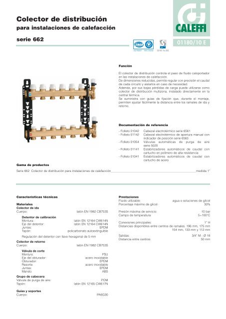
<strong>Colector</strong> <strong>de</strong> distribución<br />
para instalaciones <strong>de</strong> calefacción<br />
serie 662<br />
Gama <strong>de</strong> productos<br />
Características técnicas<br />
Materiales<br />
<strong>Colector</strong> <strong>de</strong> ida<br />
Cuerpo: latón EN 1982 CB753S<br />
Detentor <strong>de</strong> calibración<br />
Montura: latón EN 12164 CW614N<br />
Eje <strong>de</strong>l <strong>de</strong>tentor: latón EN 12164 CW614N<br />
Juntas: EPDM<br />
Tapón: policarbonato autoextinguible<br />
Regulación <strong>de</strong>l <strong>de</strong>tentor con llave hexagonal <strong>de</strong> 5 mm<br />
<strong>Colector</strong> <strong>de</strong> retorno<br />
Cuerpo: latón EN 1982 CB753S<br />
Válvula <strong>de</strong> corte<br />
Montura: PSU<br />
Eje <strong>de</strong>l obturador: acero inoxidable<br />
Obturador: EPDM<br />
Resorte: acero inoxidable<br />
Juntas: EPDM<br />
Mando:<br />
Grupo <strong>de</strong> cabecera<br />
ABS<br />
Válvula <strong>de</strong> purga <strong>de</strong> aire: POM<br />
Tapón: latón EN 12165 CW617N<br />
Guías y soportes<br />
Cuerpo: PA6G30<br />
Función<br />
CALEFFI<br />
El colector <strong>de</strong> distribución controla el paso <strong>de</strong> fluido caloportador<br />
en las instalaciones <strong>de</strong> calefacción.<br />
De dimensiones reducidas, permite regular con precisión el caudal<br />
<strong>de</strong> cada circuito y aislarlos en caso <strong>de</strong> necesidad.<br />
A<strong>de</strong>más, por sus bajas pérdidas <strong>de</strong> carga pue<strong>de</strong> utilizarse como<br />
colector <strong>de</strong> distribución multizona, instalado directamente en la<br />
central térmica.<br />
Se suministra con guías <strong>de</strong> fijación que, durante el montaje,<br />
permiten ajustar fácilmente la distancia entre los ramales <strong>de</strong> ida y<br />
retorno.<br />
Serie 662 <strong>Colector</strong> <strong>de</strong> distribución para instalaciones <strong>de</strong> calefacción medida 1”<br />
ACCREDITED<br />
ISO 9001 FM 21654<br />
ISO 9001 No. 0003<br />
Documentación <strong>de</strong> referencia<br />
01180/10 E<br />
- Folleto 01042 Cabezal electrotérmico serie 6561<br />
- Folleto 01142 Cabezal electrotérmico <strong>de</strong> apertura manual con<br />
indicador <strong>de</strong> posición serie 6563<br />
- Folleto 01054 Válvulas automáticas <strong>de</strong> purga <strong>de</strong> aire<br />
serie 5020<br />
- Folleto 01141 Estabilizadores automáticos <strong>de</strong> caudal con<br />
cartucho en polímero <strong>de</strong> alta resistencia<br />
- Folleto 01041 Estabilizadores automáticos <strong>de</strong> caudal con<br />
cartucho <strong>de</strong> acero<br />
Prestaciones<br />
Fluido utilizable: agua o soluciones <strong>de</strong> glicol<br />
Porcentaje máximo <strong>de</strong> glicol: 30%<br />
Presión máxima <strong>de</strong> servicio: 10 bar<br />
Campo <strong>de</strong> temperatura: 5÷100°C<br />
Conexiones principales: 1” H<br />
Distancias disponibles entre centros <strong>de</strong> ramales: 196 mm, 175 mm<br />
154 mm, 133 mm y 112 mm<br />
Salidas: 3/4” M - Ø 18<br />
Distancia entre centros: 50 mm
Dimensiones<br />
29 196 - 175 - 154 - 133 - 112 51<br />
1”<br />
1”<br />
3/4”<br />
Código sin aisl. 6626B5 6626C5 6626D5 6626E5 6626F5 6626G5 6626H5 6626I5 6626L5 6626M5 6626N5 6626O5<br />
Nº salidas 2 3 4 5 6 7 8 9 10 11 12 13<br />
L total (A) 165 215 265 315 365 425 475 525 575 625 675 735<br />
Peso (kg) 2 2,4 2,8 3,4 3,8 4,1 4,8 5,5 6 6,9 7,2 7,7<br />
5 2 1<br />
4<br />
3<br />
50<br />
A<br />
Componentes característicos<br />
1 <strong>Colector</strong> <strong>de</strong> ida con <strong>de</strong>tentores <strong>de</strong> prerregulación<br />
<strong>de</strong>l caudal<br />
2 <strong>Colector</strong> <strong>de</strong> retorno con válvulas <strong>de</strong> corte<br />
equipables con cabezal electrotérmico<br />
3 Grupos <strong>de</strong> cabecera con válvulas <strong>de</strong> purga <strong>de</strong><br />
aire manuales, racor con doble conexión radial y<br />
tapones<br />
4 Dos guías <strong>de</strong> fijación para montaje en caja o<br />
pared<br />
5 Soportes <strong>de</strong> los colectores superiores e inferiores,<br />
para guías, con sistema <strong>de</strong> enganche rápido
Características constructivas<br />
<strong>Colector</strong> <strong>de</strong> ida<br />
1<br />
2<br />
3<br />
<strong>Colector</strong> <strong>de</strong> retorno<br />
El colector <strong>de</strong> retorno está<br />
provisto <strong>de</strong> válvulas <strong>de</strong> corte<br />
manuales (1) para cerrar el paso<br />
<strong>de</strong> líquido hacia cualquier<br />
circuito.<br />
Las válvulas pue<strong>de</strong>n equiparse<br />
con un cabezal electrotérmico (2)<br />
que, combinado con un<br />
termostato <strong>de</strong> ambiente,<br />
mantiene las temperaturas<br />
programadas aunque varíe la<br />
carga térmica.<br />
El eje <strong>de</strong>l obturador (3) es <strong>de</strong><br />
acero inoxidable rectificado para<br />
minimizar la fricción y evitar<br />
peligrosas incrustaciones.<br />
La montura tiene dos juntas tóricas<br />
<strong>de</strong> EPDM (4 y 5) sobre el eje.<br />
El obturador (6) <strong>de</strong> EPDM tiene<br />
una forma especial que optimiza<br />
las características hidráulicas <strong>de</strong><br />
la válvula y reduce al mínimo el<br />
ruido <strong>de</strong> paso <strong>de</strong>l agua, incluso<br />
durante la acción progresiva <strong>de</strong><br />
apertura o cierre en el<br />
funcionamiento con cabezal<br />
electrotérmico.<br />
<strong>Colector</strong>es componibles<br />
Los colectores se ensamblan<br />
mediante conexiones roscadas<br />
con juntas tóricas (1). Las<br />
conexiones están realizadas <strong>de</strong><br />
modo tal que, una vez<br />
enroscadas a tope, garantizan<br />
una perfecta estanqueidad al<br />
agua y la alineación <strong>de</strong> las<br />
respectivas salidas.<br />
Ensamblaje <strong>de</strong> guías y<br />
colectores<br />
Los colectores se montan<br />
fácilmente en las guías (1)<br />
mediante los soportes<br />
componibles (2) incluidos en el<br />
suministro, sin necesidad <strong>de</strong><br />
accesorios <strong>de</strong> montaje como<br />
tuercas y llaves <strong>de</strong> apriete.<br />
El colector <strong>de</strong> ida está provisto <strong>de</strong><br />
<strong>de</strong>tentores para calibrar y aislar los<br />
circuitos <strong>de</strong>rivados.<br />
La perfecta estanqueidad hidráulica<br />
<strong>de</strong>l conjunto, esencial para evitar<br />
pérdidas con el paso <strong>de</strong>l tiempo, se<br />
obtiene mediante juntas tóricas <strong>de</strong><br />
EPDM en la montura (1) y en el eje<br />
<strong>de</strong>l <strong>de</strong>tentor (2). La junta tórica <strong>de</strong>l<br />
obturador (3) permite cerrar<br />
totalmente el circuito <strong>de</strong>rivado.<br />
2<br />
1<br />
4<br />
5<br />
3<br />
6<br />
1<br />
1<br />
2<br />
Distancia entre colectores regulable<br />
Las guías tienen una serie <strong>de</strong> ranuras para enganchar manualmente<br />
los soportes <strong>de</strong> los colectores. Esto facilita el montaje <strong>de</strong>l conjunto y<br />
permite modificar la distancia entre los colectores (A o A’) en función<br />
<strong>de</strong>l espacio disponible.<br />
A<br />
Bajas pérdidas <strong>de</strong> carga<br />
Las secciones <strong>de</strong> salida <strong>de</strong> los colectores están específicamente<br />
calculadas para obtener bajas pérdidas <strong>de</strong> carga.<br />
Esto permite, como se ilustra en el esquema, utilizar el colector<br />
para abastecer dos, tres o cuatro zonas <strong>de</strong> modo in<strong>de</strong>pendiente y<br />
directamente <strong>de</strong>s<strong>de</strong> la central térmica.<br />
Un sencillo ejemplo numérico pue<strong>de</strong> <strong>de</strong>mostrar la eficacia <strong>de</strong>l<br />
dispositivo con esta función.<br />
Supóngase que se utiliza el colector serie 662 con dos salidas para<br />
enviar el fluido caloportador a dos colectores <strong>de</strong> zona con cinco<br />
salidas cada uno.<br />
Si se consi<strong>de</strong>ra un caudal medio <strong>de</strong> 700 l/h en cada colector, la<br />
pérdida media <strong>de</strong> carga causada por el colector <strong>de</strong> zona/válvula y<br />
el <strong>de</strong>tentor está alre<strong>de</strong>dor <strong>de</strong> 6 kPa.<br />
El valor calculado es equiparable a las pérdidas <strong>de</strong> carga <strong>de</strong> las<br />
válvulas <strong>de</strong> zona utilizadas en este tipo <strong>de</strong> aplicaciones.<br />
El empleo <strong>de</strong> cabezales electrotérmicos permite in<strong>de</strong>pendizar las<br />
distintas zonas bajo el control directo <strong>de</strong> los cronotermostatos<br />
respectivos.<br />
CALEFFI<br />
El control <strong>de</strong>l fluido caloportador directamente en la central térmica<br />
simplifica la conexión eléctrica <strong>de</strong> los cabezales electrotérmicos<br />
montados en el colector para el control <strong>de</strong> zona.<br />
A’<br />
CALEFFI<br />
CALEFFI<br />
TA<br />
TA
Características hidráulicas<br />
Para <strong>de</strong>terminar las características hidráulicas <strong>de</strong>l circuito, hay que calcular la pérdida <strong>de</strong> carga total que experimenta el fluido al atravesar<br />
todos los componentes <strong>de</strong>l colector y los circuitos <strong>de</strong> los radiadores.<br />
Des<strong>de</strong> el punto <strong>de</strong> vista hidráulico, el sistema formado por el colector y los circuitos se pue<strong>de</strong> esquematizar como un conjunto <strong>de</strong> elementos<br />
dispuestos en serie y en paralelo.<br />
VC = válvula <strong>de</strong> corte<br />
DT = <strong>de</strong>tentor<br />
T/R = tubería/radiador<br />
G Tot.<br />
∆PCol. I<br />
∆P Tot.<br />
∆P DT<br />
G Tot.<br />
G T/ R<br />
G T/ R<br />
G T/ R<br />
∆P T/ T/V T/VR<br />
∆P Tot.<br />
∆P T/ R<br />
∆P VI<br />
∆P Col. Retorno<br />
∆P Col. Ida<br />
∆P Coll. R<br />
∆PTot. = pérdida total en los extremos <strong>de</strong>l<br />
colector<br />
(ida + retorno + tubería/radiador)<br />
∆PDT = pérdida localizada <strong>de</strong>tentor <strong>de</strong><br />
calibración circuito (caudal circuito T/R)<br />
∆PT/R = pérdida tubería/radiador<br />
(caudal circuito T/R)<br />
∆PTot. = ∆PDT +∆PT/R + ∆PVC + ∆PCol. I + ∆PCol. R<br />
∆PVC = pérdida localizada válvula <strong>de</strong> corte<br />
circuito T/R<br />
(caudal circuito T/R)<br />
∆PCol. I = pérdida distribuida <strong>de</strong>l colector <strong>de</strong> ida<br />
(caudal total)<br />
∆PCol. R = pérdida distribuida <strong>de</strong>l colector <strong>de</strong><br />
retorno (caudal total)<br />
Conociendo las características hidráulicas <strong>de</strong> cada componente y los caudales <strong>de</strong> diseño, la pérdida total se pue<strong>de</strong> calcular como la suma <strong>de</strong><br />
las pérdidas <strong>de</strong> carga individuales <strong>de</strong> los diversos componentes, como indica la fórmula (1.1).<br />
G Tot.<br />
∆P VI<br />
∆P DT<br />
G T/ R<br />
1.1)
∆p (mm c.a.)<br />
1000<br />
500<br />
200<br />
100<br />
900<br />
800<br />
700<br />
600<br />
450<br />
400<br />
350<br />
300<br />
250<br />
180<br />
160<br />
140<br />
120<br />
90<br />
80<br />
70<br />
60<br />
50<br />
45<br />
40<br />
35<br />
30<br />
25<br />
20<br />
18<br />
16<br />
14<br />
12<br />
10<br />
0,1<br />
2<br />
0,2<br />
5<br />
Detentor todo abierto (DT)<br />
Válvula <strong>de</strong> corte (VC)<br />
0,5<br />
10<br />
VI DT<br />
- Kv = caudal en m3 /h para una pérdida <strong>de</strong> carga <strong>de</strong> 1 bar<br />
- Kv0,01 = caudal en l/h para una pérdida <strong>de</strong> carga <strong>de</strong> 1 kPa<br />
1<br />
20<br />
Kv<br />
5,40<br />
4,10<br />
∆p (kPa)<br />
10<br />
9<br />
8<br />
7<br />
6<br />
5<br />
4,5<br />
4<br />
3,5<br />
3<br />
2,5<br />
2<br />
1,8<br />
1,6<br />
1,4<br />
1,2<br />
1<br />
0,9<br />
0,8<br />
0,7<br />
0,6<br />
Kv 0,01<br />
540<br />
410<br />
0,5<br />
0,45<br />
0,4<br />
0,35<br />
0,3<br />
0,25<br />
0,2<br />
0,18<br />
0,16<br />
0,14<br />
0,12<br />
0,1<br />
2<br />
Caudal<br />
(l/min) (m3/h) ∆p (mm c.a.)<br />
1000<br />
500<br />
200<br />
100<br />
900<br />
800<br />
700<br />
600<br />
450<br />
400<br />
350<br />
300<br />
250<br />
180<br />
160<br />
140<br />
120<br />
90<br />
80<br />
70<br />
60<br />
50<br />
45<br />
40<br />
35<br />
30<br />
25<br />
20<br />
18<br />
16<br />
14<br />
12<br />
10<br />
0,2<br />
<strong>Colector</strong> <strong>de</strong> ida/retorno 2÷7 salidas<br />
<strong>Colector</strong> <strong>de</strong> ida/retorno 8÷13 salidas<br />
* Valor medio<br />
5<br />
Col. 8÷13 salidas Col. 2÷7 salidas<br />
Ejemplo <strong>de</strong> cálculo <strong>de</strong> la pérdida <strong>de</strong> carga total<br />
Supóngase que se <strong>de</strong>sea calcular la pérdida <strong>de</strong> carga <strong>de</strong> un colector <strong>de</strong> tres salidas con las siguientes características:<br />
Caudal total colector: 410 l/h<br />
El caudal y la pérdida <strong>de</strong> carga <strong>de</strong> los tubos y radiadores <strong>de</strong> los tres circuitos son los siguientes:<br />
Circuito 1 Circuito 2 Circuito 3<br />
G1 = 80 l/h G2 = 130 l/h G3 = 200 l/h<br />
∆P Radiador 1 = 1,3 kPa ∆P Radiador 2 = 3 kPa ∆P Radiador 3 = 5,3 kPa (1.2)<br />
∆P Tubería 1 = 1,7 kPa ∆P Tubería 2 = 6,8 kPa ∆P Tubería 3 = 7,2 kPa<br />
∆P T/R1 = 1,7 + 1,3 = 3 kPa ∆P T/R2 = 6,8 + 3 = 9,8 kPa ∆P T/R3 = 7,2 + 5,3 = 12,5 kPa<br />
Se calcula cada término <strong>de</strong> la fórmula (1.1) mediante la relación:<br />
∆P = G 2 /Kv 0,01 2<br />
· G: caudal en l/h<br />
· ∆P: pérdida <strong>de</strong> carga en kPa (1 kPa =100 mm c.a.)<br />
· Kv 0,01: caudal en l/h a través <strong>de</strong>l dispositivo consi<strong>de</strong>rado al cual correspon<strong>de</strong> una pérdida <strong>de</strong> carga <strong>de</strong> 1 kPa<br />
0,5<br />
10<br />
1<br />
20<br />
2<br />
Kv<br />
16,70*<br />
10,40*<br />
∆p (kPa)<br />
10<br />
Cabe <strong>de</strong>stacar que, para calcular el ∆PTot., se <strong>de</strong>be consi<strong>de</strong>rar el circuito que tiene las mayores pérdidas <strong>de</strong> carga distribuidas a lo largo <strong>de</strong><br />
todo el circuito formado por tubería + radiador.<br />
En este caso, dicho circuito es el N° 3.<br />
Luego:<br />
∆PDT3 = 200 2 /540 2 = 0,14 kPa<br />
∆PT/R3 = 12,5 kPa<br />
∆PVC3 = 200 2 /410 2 = 0,24 kPa<br />
∆PCol. I = 410 2 /1670 2 = 0,06 kPa<br />
∆PCol. R = 410 2 /1670 2 = 0,06 kPa<br />
}<br />
Mediante la fórmula (1.1), sumando todos los términos calculados, se obtiene:<br />
∆PTot.= 0,14 +12,5 + 0,24 + 0,06 + 0,06 ≅ 13 kPa<br />
Nota:<br />
Las pérdidas <strong>de</strong> carga <strong>de</strong> los colectores son muy bajas, por lo cual se pue<strong>de</strong>n <strong>de</strong>spreciar.<br />
En general, la pérdida <strong>de</strong> carga total se aproxima bastante a la <strong>de</strong>l circuito formado por tubería, radiador y <strong>de</strong>tentor <strong>de</strong> calibración totalmente<br />
abierto.<br />
50<br />
9<br />
8<br />
7<br />
6<br />
5<br />
4,5<br />
4<br />
3,5<br />
3<br />
2,5<br />
2<br />
1,8<br />
1,6<br />
1,4<br />
1,2<br />
1<br />
0,9<br />
0,8<br />
0,7<br />
0,6<br />
0,5<br />
0,45<br />
0,4<br />
0,35<br />
0,3<br />
0,25<br />
0,2<br />
0,18<br />
0,16<br />
0,14<br />
0,12<br />
0,1<br />
Caudal<br />
(l/min) (m3/h) 5<br />
Kv 0,01<br />
1670*<br />
1040*<br />
valores obtenidos <strong>de</strong>spreciando las variaciones <strong>de</strong>bidas al trasvase <strong>de</strong> agua a los circuitos <strong>de</strong>rivados
Uso <strong>de</strong>l <strong>de</strong>tentor <strong>de</strong> calibración<br />
El <strong>de</strong>tentor <strong>de</strong> calibración permite equilibrar los diversos circuitos <strong>de</strong> los radiadores para obtener los caudales nominales en cada uno <strong>de</strong> ellos.<br />
Se consi<strong>de</strong>ra que cada circuito está formado por: <strong>de</strong>tentor, tubería/radiador y válvula <strong>de</strong> corte. Para calibrar correctamente el sistema, es<br />
preciso conocer los siguientes datos:<br />
· caudal <strong>de</strong> fluido que <strong>de</strong>be atravesar cada circuito (dato <strong>de</strong> diseño)<br />
· pérdida <strong>de</strong> carga que se genera en cada circuito con dicho caudal:<br />
· pérdida <strong>de</strong> carga <strong>de</strong>l circuito más <strong>de</strong>sfavorecido:<br />
En todos los circuitos, en presencia <strong>de</strong>l caudal GCircuito, el<br />
<strong>de</strong>tentor <strong>de</strong>be crear una pérdida <strong>de</strong> carga suplementaria<br />
igual a la diferencia, que po<strong>de</strong>mos indicar como ∆PDT (∆P<br />
<strong>de</strong>tentor).<br />
Para permitir un eventual incremento <strong>de</strong>l caudal, a veces<br />
se consi<strong>de</strong>ra la mayor pérdida <strong>de</strong> carga con el <strong>de</strong>tentor<br />
abierto al 80%.<br />
Una vez conocidos los datos ∆PDT y GCircuito <strong>de</strong> cada<br />
circuito, en la gráfica <strong>de</strong> características hidráulicas <strong>de</strong>l<br />
<strong>de</strong>tentor se pue<strong>de</strong> elegir la curva <strong>de</strong> regulación i<strong>de</strong>al<br />
correspondiente a la posición <strong>de</strong> regulación <strong>de</strong> la válvula.<br />
Ejemplo <strong>de</strong> prerregulación<br />
Supóngase que se <strong>de</strong>sea equilibrar tres circuitos con las pérdidas <strong>de</strong> carga y el caudal <strong>de</strong>l conjunto tubería/radiador indicados en el ejemplo (1.2).<br />
Dado que el circuito N° 3 es el más <strong>de</strong>sfavorecido por tener la mayor pérdida <strong>de</strong> carga en el conjunto tubería/radiador,<br />
hay que regular los otros circuitos:<br />
Circuito 3 Circuito 1 Circuito 2<br />
∆PT/R3 = 12,5 kPa ∆PT/R1 = 3 kPa ∆PT/R2 = 9,8 kPa<br />
G3 = 200 l/h G1 = 80 l/h G2 = 130 l/h<br />
∆PDT3 = 200 2 /540 2 = 0,14 kPa<br />
∆PVC3 = 200 2 /410 2 = 0,24 kPa ∆PVC1 = 80 2 /410 2 = 0,04 kPa ∆PVC2 =130 2 /410 2 = 0,1 kPa<br />
Con la fórmula (1.4): con la fórmula (1.3): con la fórmula (1.3):<br />
∆PCircuito 3 = 0,14 + 12,5 + 0,24 ≅ 13 kPa ∆PCircuito 1 = 3,0 + 0,04 ≅ 3 kPa ∆PCircuito 2 = 9,8 + 0,1 = 9,9 kPa<br />
+ <strong>de</strong>sfavorecido<br />
Para <strong>de</strong>terminar la posición <strong>de</strong> regulación <strong>de</strong><br />
los <strong>de</strong>tentores <strong>de</strong> los circuitos 1 y 2, hacen<br />
falta los siguientes datos:<br />
Circuito 1<br />
∆PDT1 = 13 - 3 = 10 kPa<br />
G1 = 80 l/h<br />
N° vueltas <strong>de</strong> regulación: 2<br />
Circuito 2<br />
∆PDT2 = 13 - 9,9 = 3,1 kPa<br />
G2 = 130 l/h<br />
N° vueltas <strong>de</strong> regulación: ≅ 2,5*<br />
Circuito 3<br />
Posición <strong>de</strong> regulación todo abierto<br />
* Aproximación por exceso o por <strong>de</strong>fecto<br />
a la curva más cercana en la gráfica <strong>de</strong><br />
regulación<br />
∆PCircuito = ∆PT/R + ∆PVC (1.3)<br />
∆PCircuito = ∆PDT + ∆PT/R + ∆PVC (1.4)<br />
+ <strong>de</strong>sfavorecido<br />
RETORNO<br />
INSTALACIÓN<br />
IDA<br />
INSTALACIÓN<br />
∆PCircuito ≅ 13 kPa<br />
+ <strong>de</strong>sfavorecido<br />
∆p (mm c.a.)<br />
5000<br />
4500<br />
4000<br />
3500<br />
3000<br />
2500<br />
2000<br />
1800<br />
1600<br />
1400<br />
1200<br />
1000<br />
900<br />
800<br />
700<br />
600<br />
500<br />
450<br />
400<br />
350<br />
300<br />
250<br />
200<br />
180<br />
160<br />
140<br />
120<br />
100<br />
0,020<br />
0,025<br />
0,030<br />
0,5<br />
5 mm<br />
0,035<br />
0,040<br />
0,045<br />
0,05<br />
∆P Tot.<br />
0,06<br />
0,07<br />
0,08<br />
0,09<br />
0,1<br />
0,12<br />
0,14<br />
0,16<br />
0,18<br />
0,2<br />
0,25<br />
VI<br />
0,30<br />
0,35<br />
0,40<br />
0,45<br />
0,5<br />
∆P Circuito +<br />
<strong>de</strong>sfav.<br />
∆T<br />
∆PCircuito<br />
∆P 1<br />
∆P∆T<br />
∆P DT1<br />
∆PCircuito<br />
+ <strong>de</strong>sfav.<br />
∆P 2<br />
∆P DT2<br />
2 2,5 3 3,5 4 TA<br />
∆p (kPa)<br />
50<br />
45<br />
40<br />
35<br />
30<br />
25<br />
20<br />
18<br />
16<br />
14<br />
12<br />
10<br />
9<br />
8<br />
7<br />
6<br />
5<br />
4,5<br />
4,0<br />
3,5<br />
3,0<br />
2,5<br />
2<br />
1,8<br />
1,6<br />
1,4<br />
1,2<br />
1<br />
1<br />
2<br />
5<br />
0,6<br />
0,7<br />
10<br />
0,8<br />
0,9<br />
1,0<br />
1,2<br />
1,4<br />
1,6<br />
1,8<br />
2,0<br />
Caudal<br />
(l/min) (m3/h) 20<br />
∆P 3
Características hidráulicas <strong>de</strong>l <strong>de</strong>tentor<br />
∆p (mm c.a.)<br />
5000<br />
4500<br />
4000<br />
3500<br />
3000<br />
2500<br />
2000<br />
1800<br />
1600<br />
1400<br />
1200<br />
1000<br />
900<br />
800<br />
700<br />
600<br />
500<br />
200<br />
100<br />
450<br />
400<br />
350<br />
300<br />
250<br />
180<br />
160<br />
140<br />
120<br />
0,020<br />
0,025<br />
0,030<br />
0,5<br />
0,035<br />
Posición <strong>de</strong> regulación<br />
Kv<br />
Kv0,01<br />
5 mm<br />
0,040<br />
0,045<br />
0,05<br />
1<br />
2 2,5 3 3,5 4 TA<br />
0,06<br />
2<br />
0,22<br />
- Kv = caudal en m3 /h para una pérdida <strong>de</strong> carga <strong>de</strong> 1 bar<br />
- Kv0,01 = caudal en l/h para una pérdida <strong>de</strong> carga <strong>de</strong> 1 kPa<br />
22<br />
0,07<br />
0,08<br />
0,09<br />
0,1<br />
0,12<br />
2<br />
0,14<br />
2,5<br />
0,60<br />
60<br />
0,16<br />
0,18<br />
0,2<br />
ESPECIFICACIONES<br />
Serie 662<br />
<strong>Colector</strong> <strong>de</strong> distribución para instalaciones <strong>de</strong> calefacción con 2 (<strong>de</strong> 2 a 13) salidas. Cuerpo <strong>de</strong> latón. Juntas <strong>de</strong> EPDM.<br />
Conexiones <strong>de</strong> cabecera 1” roscadas H. Distancias disponibles entre centros <strong>de</strong> ramales: 196 mm, 175 mm, 154 mm y<br />
112 mm. Conexiones salida 3/4” M - Ø 18 roscadas, distancia entre centros 50 mm. Fluido utilizable: agua o soluciones <strong>de</strong><br />
glicol. Porcentaje máximo <strong>de</strong> glicol 30%. Presión máxima <strong>de</strong> servicio 10 bar. Campo <strong>de</strong> temperatura 5÷100°C.<br />
Compuesto <strong>de</strong>:<br />
- <strong>Colector</strong> <strong>de</strong> ida provisto <strong>de</strong> <strong>de</strong>tentores <strong>de</strong> calibración con cinco vueltas completas <strong>de</strong> ajuste.<br />
- <strong>Colector</strong> <strong>de</strong> retorno dotado <strong>de</strong> válvulas <strong>de</strong> corte equipables con cabezal electrotérmico.<br />
- Grupos <strong>de</strong> cabecera formados por racor con doble conexión radial, válvula <strong>de</strong> purga <strong>de</strong> aire manual y tapón.<br />
- Dos guías <strong>de</strong> fijación para montaje en caja o pared y soportes <strong>de</strong> colectores ensamblables.<br />
- Soportes <strong>de</strong> colectores superiores e inferiores, para guías, con sistema <strong>de</strong> enganche rápido.<br />
0,25<br />
3<br />
1,30<br />
130<br />
0,30<br />
5<br />
0,35<br />
0,40<br />
0,45<br />
0,5<br />
3,5<br />
3,20<br />
320<br />
10<br />
0,6<br />
0,7<br />
0,8<br />
0,9<br />
1,0<br />
4<br />
4,70<br />
470<br />
1,2<br />
20<br />
1,4<br />
1,6<br />
1,8<br />
∆p (kPa)<br />
45<br />
40<br />
35<br />
30<br />
25<br />
18<br />
16<br />
14<br />
12<br />
9<br />
8<br />
7<br />
6<br />
5<br />
4,5<br />
4,0<br />
3,5<br />
3,0<br />
2,5<br />
2<br />
1,8<br />
1,6<br />
1,4<br />
1,2<br />
50<br />
20<br />
10<br />
1<br />
2,0<br />
Caudal<br />
(l/min) (m3/h) T.A.<br />
5,40<br />
540
COLECTORES Y ACCESORIOS<br />
Retorno<br />
instalación<br />
Ida<br />
instalación<br />
6 5 2 8 9 4 10 3<br />
7 1 14 11 12 13 17<br />
18<br />
1) <strong>Colector</strong> <strong>de</strong> ida con <strong>de</strong>tentores <strong>de</strong> prerregulación <strong>de</strong>l<br />
caudal, serie 6621<br />
2) <strong>Colector</strong> <strong>de</strong> retorno con válvulas <strong>de</strong> corte<br />
compatibles con cabezal electrotérmico, serie 6620<br />
3) Grupos <strong>de</strong> cabecera con válvulas <strong>de</strong> purga <strong>de</strong> aire manuales,<br />
racor con doble conexión radial y tapones, serie 5996<br />
4) Dos guías <strong>de</strong> fijación para montaje en caja o<br />
pared, cód. 658400<br />
5) Soportes <strong>de</strong> colectores superiores e inferiores, para guías,<br />
con sistema <strong>de</strong> enganche rápido<br />
CALEFFI<br />
15<br />
16<br />
6) AUTOFLOW ® , serie 121<br />
7) Filtro, serie 120<br />
8) Cabezal electrotérmico, serie 6561<br />
9) Cabezal electrotérmico <strong>de</strong> apertura manual con indicador <strong>de</strong><br />
posición, serie 6563<br />
10) Minigrifo <strong>de</strong> <strong>de</strong>scarga, cód. 337231<br />
11) Racor DARCAL cód. 6805 . .<br />
12) Racor DARCAL cód. 6795 . .<br />
13) Racor mecánico, cód. 3475 . .<br />
14) Disco tapón, cód. 386500<br />
15) Válvula <strong>de</strong> purga <strong>de</strong> aire automática, cód. 502033<br />
16) Kit <strong>de</strong> by-pass diferencial con calibración fija, cód. 662000<br />
17) Grifo <strong>de</strong> <strong>de</strong>scarga, cód. 538400<br />
18) Caja <strong>de</strong> alojamiento, cód. 659..4, 659..5 y 661..5
Kit <strong>de</strong> by-pass diferencial <strong>de</strong> calibración fija con tubo flexible cód. 662000<br />
Función<br />
Características técnicas<br />
Principio <strong>de</strong> funcionamiento<br />
Dentro <strong>de</strong> la válvula <strong>de</strong> by-pass hay un obturador antirretorno fijado<br />
a un resorte <strong>de</strong> empuje.<br />
Cuando se alcanza la presión <strong>de</strong> calibración fija, el obturador <strong>de</strong> la<br />
válvula se abre gradualmente. Entonces se produce una<br />
recirculación <strong>de</strong>l flujo que, al ser proporcional al cierre <strong>de</strong> las<br />
válvulas electrotérmicas, mantiene constante la presión diferencial<br />
<strong>de</strong>l circuito <strong>de</strong>l colector.<br />
Características constructivas<br />
En las instalaciones <strong>de</strong> climatización, los circuitos <strong>de</strong> distribución <strong>de</strong>l fluido caloportador se pue<strong>de</strong>n cerrar total o<br />
parcialmente mediante las válvulas electrotérmicas montadas en los colectores o con las válvulas termostáticas <strong>de</strong> los<br />
radiadores.<br />
Cuando se reduce el caudal, la presión diferencial en el circuito pue<strong>de</strong> aumentar hasta el punto <strong>de</strong> generar ruidos molestos,<br />
alta velocidad <strong>de</strong>l fluido, erosión mecánica y <strong>de</strong>sequilibrio hidráulico <strong>de</strong> la instalación.<br />
El by-pass diferencial para colectores serie 662 mantiene equilibrada la presión <strong>de</strong>l circuito colector, <strong>de</strong> ida y retorno,<br />
aunque varíe el caudal.<br />
El by-pass está formado por un tubo flexible que facilita el montaje y permite adaptar el colector en las guías <strong>de</strong> acuerdo<br />
con la posición <strong>de</strong> los tubos <strong>de</strong> ida y retorno <strong>de</strong> la instalación.<br />
Gama <strong>de</strong> productos<br />
Código 662000 Kit <strong>de</strong> by-pass diferencial <strong>de</strong> calibración fija con tubo flexible medidas 3/4” x 3/4” H con tuerca móvil<br />
Materiales<br />
Tubo flexible: acero inoxidable<br />
Tuercas: latón EN 12165 CW617N, cromado<br />
Cuerpo soporte válvula retención: latón EN 12165 CW617N, cromado<br />
Obturador: POM<br />
Resorte: acero inoxidable<br />
Juntas: EPDM<br />
Prestaciones<br />
Fluido utilizable: agua o soluciones <strong>de</strong> glicol<br />
Porcentaje máximo <strong>de</strong> glicol: 30%<br />
Presión máxima <strong>de</strong> servicio: 10 bar<br />
Campo <strong>de</strong> temperatura: 0÷100°C<br />
Presión diferencial calibración fija: 20 kPa (2000 mm c.a.)<br />
Conexiones tubo flexible: 3/4” x 1/2” H tuerca móvil<br />
Conexiones soporte válvula retención: 1/2” M x 3/4” H<br />
El by-pass diferencial tiene calibración fija, ya que no posee<br />
elementos <strong>de</strong> regulación accesibles.<br />
Está realizado en acero inoxidable trenzado y su flexibilidad facilita<br />
el montaje en el colector.<br />
La flexibilidad <strong>de</strong>l tubo también permite variar la posición <strong>de</strong> los<br />
colectores <strong>de</strong> ida y retorno en las guías, <strong>de</strong> acuerdo con la<br />
distancia que haya entre los tubos <strong>de</strong> ida y retorno <strong>de</strong> la<br />
instalación.<br />
Dimensiones<br />
Código<br />
662000<br />
Características hidráulicas<br />
Presión diferencial <strong>de</strong> by-pass: 20 kPa (2000 mm c.a.)<br />
∆p (mm c.a.)<br />
∆p (kPa)<br />
5000<br />
50<br />
4500<br />
4000<br />
3500<br />
3000<br />
2500<br />
2000<br />
1800<br />
1600<br />
1400<br />
1200<br />
1000<br />
50<br />
A<br />
3/4"<br />
60<br />
70<br />
80<br />
90<br />
100<br />
120<br />
140<br />
160<br />
180<br />
200<br />
250<br />
300<br />
350<br />
400<br />
450<br />
500<br />
600<br />
700<br />
800<br />
900<br />
Peso (Kg)<br />
0,24<br />
ESPECIFICACIONES<br />
Cód. 662000<br />
Kit <strong>de</strong> by-pass diferencial <strong>de</strong> calibración fija con tubo flexible. Conexiones 3/4” x 3/4” H tuerca móvil. Tuercas <strong>de</strong> latón,<br />
cromadas. Tubo flexible <strong>de</strong> acero inoxidable. Soporte <strong>de</strong> válvula <strong>de</strong> retención en latón. Resorte <strong>de</strong> acero inoxidable. Juntas <strong>de</strong><br />
EPDM. Fluido utilizable: agua o soluciones <strong>de</strong> glicol. Porcentaje máximo <strong>de</strong> glicol 30%. Presión máxima <strong>de</strong> servicio 10 bar.<br />
Campo <strong>de</strong> temperatura 0÷100°C. Presión diferencial <strong>de</strong> calibración fija 20 kPa.<br />
C<br />
B<br />
1/2”<br />
A<br />
CALEFFI<br />
B<br />
A<br />
C<br />
420<br />
1000<br />
45<br />
40<br />
35<br />
30<br />
25<br />
18<br />
16<br />
14<br />
12<br />
20<br />
10<br />
G (l/h)
Instalación <strong>de</strong>l by-pass<br />
Para montar el by-pass diferencial en los colectores serie 662 es necesario efectuar las siguientes operaciones:<br />
1) Con la instalación vacía, quitar los tapones <strong>de</strong> cierre (A) <strong>de</strong> los grupos <strong>de</strong> cabecera <strong>de</strong> los colectores <strong>de</strong> ida y retorno.<br />
2) Enroscar en el grupo <strong>de</strong> cabecera <strong>de</strong>l colector <strong>de</strong> retorno el soporte <strong>de</strong> la válvula <strong>de</strong> retención (B) suministrado <strong>de</strong> serie, utilizando<br />
empaquetadura <strong>de</strong> cáñamo, cinta <strong>de</strong> PTFE u otro elemento <strong>de</strong> estanqueidad.<br />
3) Montar el tubo flexible (C) en los grupos <strong>de</strong> cabecera <strong>de</strong> los dos colectores mediante las tuercas móviles, previa colocación <strong>de</strong> las juntas<br />
(D) suministradas.<br />
Estabilizadores automáticos <strong>de</strong> caudal<br />
121 AUTOFLOW ®<br />
Combinación <strong>de</strong> estabilizador automático <strong>de</strong> caudal y válvula <strong>de</strong> esfera.<br />
Cuerpo <strong>de</strong> latón.<br />
Cartucho AUTOFLOW<br />
folleto 01141<br />
® en polímero <strong>de</strong> alta resistencia.<br />
Presión máxima <strong>de</strong> servicio: 16 bar<br />
Campo <strong>de</strong> temperatura: 0÷100°C<br />
Porcentaje máximo <strong>de</strong> glicol: 50%<br />
Rango ∆π: 15÷200 kPa<br />
Caudal: 0,12÷4,5 m3 /h<br />
Precisión: ±10%<br />
Permite conectar tomas <strong>de</strong> presión y válvula <strong>de</strong> <strong>de</strong>scarga.<br />
Para el uso en tuberías con aislamiento, la palanca reversible pue<strong>de</strong> sustituirse por la versión larga.<br />
Solicitud <strong>de</strong> patente nº MI2004A001549.<br />
Código<br />
121141● ● ●<br />
121151● ● ●<br />
121161● ● ●<br />
121171● ● ●<br />
1 2 3<br />
A<br />
1/2”<br />
3/4”<br />
1”<br />
1 1/4”<br />
Kv (m 3 /h)<br />
16,90<br />
17,73<br />
18,00<br />
18,50<br />
∆π mínimo <strong>de</strong><br />
trabajo (kPa)<br />
15<br />
15<br />
15<br />
15<br />
B C<br />
Rango ∆π<br />
(kPa)<br />
15÷200<br />
15÷200<br />
15÷200<br />
15÷200<br />
120 FILTRO folleto 01041<br />
Combinación <strong>de</strong> filtro y válvula <strong>de</strong> esfera.<br />
Cuerpo <strong>de</strong> latón.<br />
Cartucho filtro <strong>de</strong> acero inoxidable.<br />
Presión máxima <strong>de</strong> servicio: 25 bar<br />
Campo <strong>de</strong> temperatura: 0÷110°C<br />
Porcentaje máximo <strong>de</strong> glicol: 50%<br />
Malla <strong>de</strong>l filtro Ø: 1/2”÷1 1/4”: 0,87 mm; 1 1/2” y 2”: 0,73 mm<br />
Permite conectar tomas <strong>de</strong> presión y válvula <strong>de</strong> <strong>de</strong>scarga.<br />
Para el uso en tuberías con aislamiento, la palanca reversible pue<strong>de</strong> sustituirse por la versión larga.<br />
Código<br />
120141 000<br />
120151 000<br />
120161 000<br />
120171 000<br />
120181 000<br />
120191 000<br />
1/2”<br />
3/4”<br />
1”<br />
1 1/4”<br />
1 1/2”<br />
2”<br />
Kv (m 3 /h)<br />
16,87<br />
17,25<br />
16,65<br />
17,23<br />
39,13<br />
39,69<br />
CALEFFI CALEFFI<br />
D<br />
CALEFFI
Cabezales electrotérmicos<br />
6561 folleto 01042<br />
Cabezal electrotérmico<br />
para colectores serie 662.<br />
Normalmente cerrado.<br />
Código Tensión (V)<br />
656102<br />
656104<br />
656112<br />
656114<br />
230<br />
224<br />
6561 folleto 01042<br />
Cabezal electrotérmico<br />
para colectores serie 662.<br />
Normalmente cerrado.<br />
Con microinterruptor auxiliar.<br />
Código<br />
Tensión (V)<br />
230<br />
224<br />
Cabezales electrotérmicos <strong>de</strong> apertura manual con indicador <strong>de</strong> posición<br />
6563 folleto 01142<br />
Cabezal electrotérmico<br />
para colectores serie 662.<br />
Normalmente cerrado.<br />
Código Tensión (V)<br />
656302<br />
656304<br />
656312<br />
656314<br />
230<br />
224<br />
6563 folleto 01142<br />
Cabezal electrotérmico<br />
para colectores serie 662.<br />
Normalmente cerrado.<br />
Con microinterruptor auxiliar.<br />
Código<br />
Tensión (V)<br />
230<br />
224<br />
Características técnicas<br />
Materiales<br />
Carcasa protectora: policarbonato autoextinguible<br />
Color: (cód. 656102/04) blanco RAL 9010<br />
(cód. 656112/14) gris RAL 9002<br />
Normalmente cerrado<br />
Alimentación eléctrica: 230 V (ac) - 24 V (ac) - 24 V (dc)<br />
Corriente <strong>de</strong> arranque ≤ 1 A<br />
Corriente en régimen: 230 V (ac) = 13 mA<br />
24 V (ac) - 24 V (dc) = 140 mA<br />
Potencia absorbida en régimen: 3 W<br />
Capacidad contactos micr. auxiliar (cód. 656112/114): 0,8 A (230 V)<br />
Grado <strong>de</strong> protección: IP 44 (en posición vertical)<br />
Doble aislamiento: CE<br />
Temperatura ambiente máxima: 50°C<br />
Tiempo <strong>de</strong> actuación: apertura y cierre <strong>de</strong> 120 s a 180 s<br />
Longitud cable <strong>de</strong> alimentación: 80 cm<br />
Características técnicas<br />
Materiales<br />
Carcasa protectora: policarbonato autoextinguible<br />
Color: (cód. 656302/04) blanco RAL 9010<br />
(cód. 656312/14) gris RAL 9002<br />
Normalmente cerrado<br />
Alimentación eléctrica: 230 V (ac) - 24 V (ac) - 24 V (dc)<br />
Corriente <strong>de</strong> arranque ≤ 1 A<br />
Corriente en régimen: 230 V (ac) = 13 mA<br />
24 V (ac) - 24 V (dc) = 140 mA<br />
Potencia absorbida en régimen: 3 W<br />
Capacidad contactos micr. auxiliar (cód. 656312/14): 0,8 A (230 V)<br />
Grado <strong>de</strong> protección: IP 40<br />
Doble aislamiento: CE<br />
Temperatura ambiente máxima: 50°C<br />
Tiempo <strong>de</strong> actuación: apertura y cierre <strong>de</strong> 120 s a 180 s<br />
Longitud cable <strong>de</strong> alimentación: 80 cm<br />
Solicitud <strong>de</strong> patente nº MI2005A000742.<br />
El cabezal electrotérmico serie 6563 está provisto <strong>de</strong> mando para la apertura manual, indicador <strong>de</strong> apertura/cierre <strong>de</strong> la válvula y dispositivo<br />
<strong>de</strong> retorno al funcionamiento automático <strong>de</strong>s<strong>de</strong> la posición manual cuando se restablece la alimentación eléctrica.<br />
El mando <strong>de</strong> apertura manual y el retorno<br />
automático <strong>de</strong> la posición manual a la automática<br />
son particularmente útiles durante la inspección o<br />
el mantenimiento <strong>de</strong> la instalación, en caso <strong>de</strong> que:<br />
- sea necesario efectuar controles hidráulicos,<br />
porque evita tener que conectar y alimentar<br />
eléctricamente los mandos;<br />
- se <strong>de</strong>je el mando en posición manual <strong>de</strong>spués<br />
<strong>de</strong> haber realizado el control. En este caso,<br />
cuando se energiza el sistema, el mando se<br />
dispone por sí solo en funcionamiento<br />
automático.
<strong>Colector</strong>es<br />
Código<br />
662625<br />
662635<br />
662645<br />
662655<br />
662665<br />
Código<br />
662025<br />
662035<br />
662045<br />
662055<br />
662065<br />
Grifo <strong>de</strong> <strong>de</strong>scarga<br />
Código<br />
Conexión<br />
1”<br />
1”<br />
1”<br />
1”<br />
1”<br />
538400 1/2” M<br />
Guías <strong>de</strong> fijación<br />
Código<br />
658400<br />
658401<br />
Conexión<br />
1”<br />
1”<br />
1”<br />
1”<br />
1”<br />
2<br />
3<br />
4<br />
5<br />
6<br />
662<br />
Par <strong>de</strong> colectores con válvulas <strong>de</strong> corte y<br />
<strong>de</strong> prerregulación.<br />
Presión máxima <strong>de</strong> servicio: 10 bar.<br />
Campo <strong>de</strong> temperatura: 5÷100°C.<br />
Distancia entre centros <strong>de</strong> las<br />
salidas: 50 mm<br />
Nº<br />
sal. Salidas<br />
2<br />
3<br />
4<br />
5<br />
6<br />
3/4” M<br />
3/4” M<br />
3/4” M<br />
3/4” M<br />
3/4” M<br />
6620<br />
<strong>Colector</strong> <strong>de</strong> retorno con válvulas <strong>de</strong> corte<br />
equipables con cabezal electrotérmico.<br />
Presión máxima <strong>de</strong> servicio: 10 bar<br />
Campo <strong>de</strong> temperatura: 5÷100°C<br />
Distancia entre centros <strong>de</strong> las<br />
salidas: 50 mm<br />
Nº<br />
sal. Salidas<br />
3/4” M<br />
3/4” M<br />
3/4” M<br />
3/4” M<br />
3/4” M<br />
538<br />
Grifo <strong>de</strong> <strong>de</strong>scarga con adaptador y tapón.<br />
Presión máxima <strong>de</strong> servicio: 10 bar<br />
Temperatura máxima <strong>de</strong> servicio: 110°C<br />
658<br />
Guías <strong>de</strong> fijación en polímero con<br />
distancia entre centros regulable<br />
para colectores serie 662.<br />
Con tornillos y tacos <strong>de</strong> expansión.<br />
Para instalar en cajas serie 659 o<br />
directamente en la pared.<br />
Profundidad caja<br />
110÷140<br />
280÷120<br />
Código<br />
662125<br />
662135<br />
662145<br />
662155<br />
662165<br />
Válvulas <strong>de</strong> purga <strong>de</strong> aire<br />
Código<br />
Conexión<br />
1”<br />
1”<br />
1”<br />
1”<br />
1”<br />
337231 3/8” M<br />
6621<br />
<strong>Colector</strong> <strong>de</strong> ida con válvulas <strong>de</strong><br />
prerregulación.<br />
Presión máxima <strong>de</strong> servicio: 10 bar.<br />
Campo <strong>de</strong> temperatura: 5÷100°C.<br />
Distancia entre centros <strong>de</strong> las<br />
salidas: 50 mm<br />
Nº<br />
sal. Salidas<br />
2<br />
3<br />
4<br />
5<br />
6<br />
3/4” M<br />
3/4” M<br />
3/4” M<br />
3/4” M<br />
3/4” M<br />
Materiales<br />
<strong>Colector</strong> <strong>de</strong> ida<br />
Cuerpo: latón EN 1982 CB753S<br />
Detentor <strong>de</strong> calibración<br />
Montura: latón EN 12164 CW614N<br />
Eje <strong>de</strong>l <strong>de</strong>tentor: latón EN 12164 CW614N<br />
Juntas: EPDM<br />
Tapón: policarbonato autoextinguible<br />
Regulación <strong>de</strong>l <strong>de</strong>tentor con llave hexagonal <strong>de</strong> 5 mm<br />
<strong>Colector</strong> <strong>de</strong> retorno<br />
Cuerpo:<br />
Válvula <strong>de</strong> corte<br />
latón EN 1982 CB753S<br />
Montura: PSU<br />
Eje <strong>de</strong>l obturador: acero inoxidable<br />
Obturador: EPDM<br />
Resorte: acero inoxidable<br />
Juntas: EPDM<br />
Mando:<br />
Prestaciones<br />
ABS<br />
Presión máxima <strong>de</strong> servicio: 10 bar<br />
Campo <strong>de</strong> temperatura: 5÷100°C<br />
Conexiones principales: 1” H<br />
Salidas: 3/4” M - Ø 18<br />
Distancia entre centros: 50 mm<br />
Código<br />
502033 3/8” M<br />
5020<br />
Válvula automática <strong>de</strong> purga <strong>de</strong> aire.<br />
De latón estampado.<br />
Con tapón higroscópico <strong>de</strong> seguridad.<br />
Presión máxima <strong>de</strong> servicio: 10 bar<br />
Presión máxima <strong>de</strong> <strong>de</strong>scarga: 2,5 bar<br />
Temperatura máxima <strong>de</strong> servicio: 120°C<br />
337<br />
Minigrifo <strong>de</strong> <strong>de</strong>scarga con junta metálica.<br />
Descarga orientable.<br />
Rosca con junta <strong>de</strong> PTFE.<br />
Presión máxima <strong>de</strong> servicio: 10 bar<br />
Temperatura máxima <strong>de</strong> servicio: 100°C
Grupo <strong>de</strong> cabecera<br />
5996<br />
Grupo <strong>de</strong> cabecera con válvula <strong>de</strong><br />
purga <strong>de</strong> aire y tapón.<br />
Presión máxima <strong>de</strong> servicio: 10 bar<br />
Campo <strong>de</strong> temperatura: 5÷100°C<br />
Conexión principal: 1” H<br />
Conexión inferior: 3/4” M<br />
Conexión purga <strong>de</strong> aire superior: 3/8” H<br />
Conexión tapón inferior: 1/2” H<br />
Código<br />
599662 1” H<br />
Racores<br />
Código<br />
680507<br />
680502<br />
680503<br />
680500<br />
680501<br />
680506<br />
680515<br />
680517<br />
680524<br />
680526<br />
680535<br />
680537<br />
680544<br />
680546<br />
680555<br />
680556<br />
680564<br />
680505<br />
Código<br />
347510<br />
347512<br />
347514<br />
347515<br />
347516<br />
347518<br />
3/4”<br />
3/4”<br />
3/4”<br />
3/4”<br />
3/4”<br />
3/4”<br />
3/4”<br />
3/4”<br />
3/4”<br />
3/4”<br />
3/4”<br />
3/4”<br />
3/4”<br />
3/4”<br />
3/4”<br />
3/4”<br />
3/4”<br />
3/4”<br />
680<br />
Racor <strong>de</strong> diámetro autoadaptable para<br />
tubos <strong>de</strong> material plástico monocapa o<br />
multicapa.<br />
Presión máxima <strong>de</strong> servicio: 10 bar<br />
Campo <strong>de</strong> temperatura: 5÷80°C (PE-X)<br />
5÷75°C (multicapa marcado 95°C)<br />
Patentado.<br />
Øinterior Øexterior 17,5÷18,0<br />
17,5÷18,0<br />
8,5÷19,<br />
9,÷ 9,5<br />
19,5÷10,0<br />
19,5÷10,0<br />
10,5÷11,0<br />
10,5÷11,0<br />
11,5÷12,0<br />
11,5÷12,0<br />
12,5÷13,0<br />
12,5÷13,0<br />
13,5÷14,0<br />
13,5÷14,0<br />
14,5÷15,0<br />
15 ÷15,5<br />
15,5÷16<br />
17<br />
3/4” - Ø 10<br />
3/4” - Ø 12<br />
3/4” - Ø 14<br />
3/4” - Ø 15<br />
3/4” - Ø 16<br />
3/4” - Ø 18<br />
10,5÷12<br />
12,5÷14<br />
12,5÷14<br />
14,5÷16<br />
12,5÷14<br />
14,5÷16<br />
14,5÷16<br />
16,5÷18<br />
14,5÷16<br />
16,5÷18<br />
16,5÷18<br />
18,5÷20<br />
16,5÷18<br />
18,5÷20<br />
18,5÷20<br />
18,5÷20<br />
18,5÷20<br />
22,50<br />
1”<br />
3/4”<br />
3/8”<br />
1/2”<br />
3/4”<br />
347<br />
Racor mecánico para tubos <strong>de</strong> cobre<br />
recocido o crudo, latón, acero dulce y<br />
acero inoxidable.<br />
Con junta tórica.<br />
Presión máxima <strong>de</strong> servicio: 10 bar<br />
Campo <strong>de</strong> temperatura: -25÷120°C<br />
Código<br />
386500 3/4”<br />
Código<br />
679001<br />
679002<br />
679003<br />
679004<br />
679006<br />
679007<br />
679008<br />
679009<br />
386<br />
Disco tapón con tuerca para<br />
salidas <strong>de</strong> los colectores.<br />
679<br />
Racor para tubos multicapa <strong>de</strong><br />
funcionamiento continuo a alta<br />
temperatura.<br />
Presión máxima <strong>de</strong> servicio: 10 bar<br />
Campo <strong>de</strong> temperatura: 0÷95°C<br />
Cromado.<br />
Para el uso correcto <strong>de</strong> estos nuevos racores es necesario calibrar<br />
el tubo multicapa antes <strong>de</strong>l uso mediante el calibrador <strong>Caleffi</strong> serie 679.<br />
Código<br />
679514<br />
679524<br />
679525<br />
679544<br />
679564<br />
679565<br />
679566<br />
3/4” - Ø 14x2<br />
3/4” - Ø 16x2<br />
3/4” - Ø 16x2,25<br />
3/4” - Ø 18x2<br />
3/4” - Ø 20x2<br />
3/4” - Ø 20x2,25<br />
3/4” - Ø 20x2,5<br />
Calibrador Ø 14x2<br />
Calibrador Ø 16x2<br />
Calibrador Ø 16x2,25<br />
Calibrador Ø 18x2<br />
Calibrador Ø 20x2<br />
Calibrador Ø 20x2,25<br />
Calibrador Ø 20x2,5<br />
Empuñadura para calibrador pulido<br />
679<br />
Calibrador y empuñadura para<br />
calibrar tubos multicapa antes <strong>de</strong>l<br />
uso con racores serie 679.<br />
Calibración <strong>de</strong>l tubo multicapa y montaje <strong>de</strong> los componentes <strong>de</strong>l<br />
racor serie 679<br />
Tubo Anillo retenc.tubo Tuerca Portamanguera Conexión válvula<br />
o colector
Elección <strong>de</strong>l tamaño <strong>de</strong> las cajas serie 659 y 661 en función <strong>de</strong>l número <strong>de</strong> salidas<br />
Código<br />
Nº salidas<br />
Long. tot. colector (mm)<br />
Long. caja (mm)<br />
Código caja serie 659<br />
Código caja serie 661<br />
Cajas <strong>de</strong> alojamiento<br />
Código (h x b x p)<br />
659044<br />
659064<br />
659084<br />
659104<br />
659124<br />
Código<br />
660040<br />
660060<br />
660080<br />
660100<br />
660120<br />
6626B5<br />
2<br />
190<br />
400<br />
65904.<br />
661045<br />
500 x 1400 x 110–140<br />
500 x 1600 x 110–140<br />
500 x 1800 x 110–140<br />
500 x 1000 x 110–140<br />
500 x 1200 x 110–140<br />
for 659044<br />
for 659064<br />
for 659084<br />
for 659104<br />
for 659124<br />
6626C5<br />
3<br />
240<br />
400<br />
65904.<br />
661045<br />
L total<br />
6626D5<br />
4<br />
290<br />
400<br />
65904.<br />
661045<br />
6626E5<br />
5<br />
340<br />
600<br />
65906.<br />
661065<br />
659<br />
Caja para colectores.<br />
Montaje en pared o suelo<br />
(con serie 660).<br />
Cierre con bloque <strong>de</strong><br />
enganche rápido.<br />
De chapa pintada.<br />
Profundidad regulable<br />
<strong>de</strong> 110 a 140 mm.<br />
660<br />
KIT para montar la caja serie 659<br />
en el suelo.<br />
Compuesto <strong>de</strong>:<br />
- 2 soportes <strong>de</strong> 20 cm <strong>de</strong> altura,<br />
- 2 paneles <strong>de</strong> cierre,<br />
- 1 barra para curvar tubos.<br />
6626F5<br />
6<br />
390<br />
600<br />
65906.<br />
661065<br />
6626G5<br />
7<br />
450<br />
600<br />
65906.<br />
661065<br />
6626H5<br />
8<br />
500<br />
600<br />
65906.<br />
661065<br />
6626I5<br />
9<br />
550<br />
800<br />
65908.<br />
661085<br />
Código (h x b x p)<br />
659045<br />
659065<br />
659085<br />
659105<br />
661045<br />
661065<br />
661085<br />
661105<br />
661125<br />
218,5<br />
6626L5<br />
10<br />
600<br />
800<br />
65908.<br />
661085<br />
500 x 1400 x 80–120<br />
500 x 1600 x 80–120<br />
500 x 1800 x 80–120<br />
500 x 1000 x 80–120<br />
Código (h x b x p)<br />
500 x 1400 x 110–150<br />
500 x 1600 x 110–150<br />
500 x 1800 x 110–150<br />
500 x 1000 x 110–150<br />
500 x 1200 x 110–150<br />
6626M5<br />
11<br />
650<br />
800<br />
65908.<br />
661085<br />
6626N5<br />
12<br />
700<br />
800<br />
65908.<br />
661085<br />
659<br />
Caja para colectores.<br />
Montaje en pared.<br />
Cierre con bloque <strong>de</strong><br />
enganche rápido.<br />
De chapa pintada.<br />
Profundidad regulable<br />
<strong>de</strong> 80 a 120 mm.<br />
661<br />
Caja para colectores.<br />
Cierre con bloque <strong>de</strong><br />
enganche rápido.<br />
De chapa pintada.<br />
Profundidad regulable<br />
<strong>de</strong> 110 a 150 mm.<br />
Con soportes para la<br />
instalación en el suelo.<br />
Altura regulable<br />
<strong>de</strong> 270 a 410 mm.<br />
6626O5<br />
13<br />
760<br />
1000<br />
65910.<br />
661105
� �� � � �� � � ��<br />
�� �<br />
Esquemas <strong>de</strong> aplicación<br />
Válvula <strong>de</strong> corte<br />
Válvula <strong>de</strong> corte <strong>de</strong> esfera<br />
Válvula manual<br />
Electrobomba<br />
Termostato ambiente<br />
Válvula <strong>de</strong> by-pass diferencial<br />
Válvula <strong>de</strong> zona<br />
Válvula termostática<br />
AUTOFLOW ® ��<br />
��� ��<br />
Instalación autónoma <strong>de</strong> radiadores con cal<strong>de</strong>ra mural <strong>de</strong> distribución directa<br />
TA<br />
TA TA<br />
CALEFFI<br />
Instalación <strong>de</strong> calefacción <strong>de</strong> zona y válvula <strong>de</strong> by-pass diferencial<br />
CALEFFI�TA<br />
TA<br />
CALEFFI<br />
��<br />
��<br />
�� ��<br />
�� ��
El fabricante se reserva el <strong>de</strong>recho <strong>de</strong> modificar los productos <strong>de</strong>scritos y los datos técnicos correspondientes en cualquier momento y sin aviso previo.<br />
CALEFFI<br />
CALEFFI S.P.A. · S.R.229, N.25 · 28010 FONTANETO D’AGOGNA (NO) · ITALIA · TEL. +39 0322 8491 · FAX +39 0322 863723<br />
· www.caleffi.es · info@caleffi.com ·<br />
© Copyright 2010 <strong>Caleffi</strong>


