

Colector premontado de distribución para instalaciones de ... - Caleffi
Colector premontado de distribución para instalaciones de ... - Caleffi
Colector premontado de distribución para instalaciones de ... - Caleffi

Create successful ePaper yourself
Turn your PDF publications into a flip-book with our unique Google optimized e-Paper software.
<strong>Colector</strong> <strong>premontado</strong> <strong>de</strong> distribución<br />
<strong>para</strong> <strong>instalaciones</strong> <strong>de</strong> suelo radiante<br />
serie 668...S1<br />
Gama <strong>de</strong> productos<br />
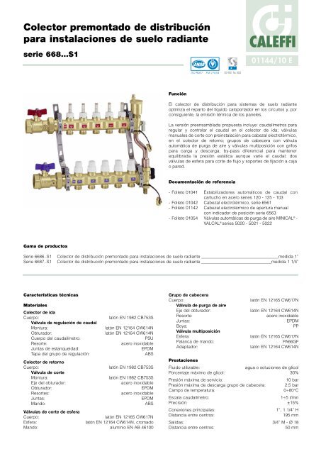
Función<br />
01144/10 E<br />
El colector <strong>de</strong> distribución <strong>para</strong> sistemas <strong>de</strong> suelo radiante<br />
optimiza el reparto <strong>de</strong>l líquido caloportador en los circuitos y, por<br />
consiguiente, la emisión térmica <strong>de</strong> los paneles.<br />
La versión preensamblada propuesta incluye: caudalímetros <strong>para</strong><br />
regular y controlar el caudal en el colector <strong>de</strong> ida; válvulas<br />
manuales <strong>de</strong> corte con preinstalación <strong>para</strong> cabezal electrotérmico,<br />
en el colector <strong>de</strong> retorno; grupos <strong>de</strong> cabecera con válvula<br />
automática <strong>de</strong> purga <strong>de</strong> aire y válvulas multiposición con grifos<br />
<strong>para</strong> carga y <strong>de</strong>scarga; by-pass diferencial <strong>para</strong> mantener<br />
equilibrada la presión estática aunque varíe el caudal; dos<br />
válvulas <strong>de</strong> esfera <strong>para</strong> corte <strong>de</strong> flujo y soportes <strong>de</strong> fijación a caja<br />
o pared.<br />
Documentación <strong>de</strong> referencia<br />
CALEFFI<br />
- Folleto 01041 Estabilizadores automáticos <strong>de</strong> caudal con<br />
cartucho en acero series 120 - 125 - 103<br />
- Folleto 01042 Cabezal electrotérmico, serie 6561<br />
- Folleto 01142 Cabezal electrotérmico <strong>de</strong> apertura manual<br />
con indicador <strong>de</strong> posición serie 6563<br />
- Folleto 01054 Válvulas automáticas <strong>de</strong> purga <strong>de</strong> aire MINICAL ® -<br />
VALCAL ® series 5020 - 5021 - 5022<br />
Serie 6686..S1 <strong>Colector</strong> <strong>de</strong> distribución <strong>premontado</strong> <strong>para</strong> <strong>instalaciones</strong> <strong>de</strong> suelo radiante medida 1”<br />
Serie 6687..S1 <strong>Colector</strong> <strong>de</strong> distribución <strong>premontado</strong> <strong>para</strong> <strong>instalaciones</strong> <strong>de</strong> suelo radiante medida 1 1/4”<br />
Características técnicas<br />
Materiales<br />
<strong>Colector</strong> <strong>de</strong> ida<br />
Cuerpo:<br />
Válvula <strong>de</strong> regulación <strong>de</strong> caudal<br />
latón EN 1982 CB753S<br />
Montura: latón EN 12164 CW614N<br />
Obturador: latón EN 12164 CW614N<br />
Cuerpo <strong>de</strong>l caudalímetro: PSU<br />
Resorte: acero inoxidable<br />
Juntas <strong>de</strong> estanqueidad: EPDM<br />
Tapa <strong>de</strong>l grupo <strong>de</strong> regulación: ABS<br />
<strong>Colector</strong> <strong>de</strong> retorno<br />
Cuerpo: latón EN 1982 CB753S<br />
Válvula <strong>de</strong> corte<br />
Montura: latón EN 1982 CB753S<br />
Eje <strong>de</strong>l obturador: acero inoxidable<br />
Obturador: EPDM<br />
Resortes: acero inoxidable<br />
Juntas: EPDM<br />
Mando: ABS<br />
Válvulas <strong>de</strong> corte <strong>de</strong> esfera<br />
Cuerpo: latón EN 12165 CW617N<br />
Esfera: latón EN 12164 CW614N, cromado<br />
Mando: aluminio EN AB 46100<br />
ACCREDITED<br />
ISO 9001 FM 21654<br />
ISO 9001 No. 0003<br />
Grupo <strong>de</strong> cabecera<br />
Cuerpo: latón EN 12165 CW617N<br />
Válvula <strong>de</strong> purga <strong>de</strong> aire<br />
Eje <strong>de</strong>l obturador: latón EN 12164 CW614N<br />
Resorte: acero inoxidable<br />
Juntas: EPDM<br />
Boya: PP<br />
Válvula multiposición<br />
Esfera: latón EN 12165 CW617N<br />
Palanca <strong>de</strong> mando: PA66GF<br />
Adaptador: latón EN 12164 CW614N<br />
Prestaciones<br />
Fluido utilizable: agua o soluciones <strong>de</strong> glicol<br />
Porcentaje máximo <strong>de</strong> glicol: 30%<br />
Presión máxima <strong>de</strong> servicio: 10 bar<br />
Presión máxima <strong>de</strong> <strong>de</strong>scarga grupo <strong>de</strong> cabecera: 2,5 bar<br />
Campo <strong>de</strong> temperatura: 0÷80°C<br />
Escala caudalímetro: 1÷5 l/min<br />
Precisión: ±15%<br />
Conexiones principales: 1”, 1 1/4” H<br />
Distancia entre centros: 195 mm<br />
Salidas: 3/4” M - Ø 18<br />
Distancia entre centros: 50 mm
Dimensiones<br />
59 195<br />
108<br />
Código (1”)<br />
Código (1 1/4”)<br />
N salidas<br />
L TOTAL<br />
Peso (kg)<br />
1” o 1 1/4”<br />
1” o 1 1/4”<br />
6686C5S1<br />
6687C5S1<br />
3<br />
380<br />
7,2<br />
6686D5S1<br />
6687D5S1<br />
4<br />
430<br />
7,8<br />
1<br />
2<br />
3<br />
4<br />
L/MIN<br />
CAMERA<br />
CALEFFI<br />
6686E5S1<br />
6687E5S1<br />
5<br />
480<br />
8,3<br />
25<br />
1<br />
2<br />
3<br />
4<br />
L/MIN<br />
HOBBY BAGNO<br />
SOGGIORNO<br />
WC<br />
L TOTAL<br />
6686F5S1<br />
6687F5S1<br />
6<br />
530<br />
9,4<br />
6 7 1 2 7 3 5 4<br />
1<br />
2<br />
3<br />
4<br />
L/MIN<br />
CAMERA<br />
CALEFFI<br />
CAMERA<br />
CALEFFI<br />
1<br />
2<br />
3<br />
4<br />
L/MIN<br />
HOBBY<br />
HOBBY<br />
1<br />
2<br />
3<br />
4<br />
L/MIN<br />
SOGGIORNO<br />
SOGGIORNO<br />
CALEFF<br />
1<br />
2<br />
3<br />
4<br />
L/MIN<br />
WC<br />
WC<br />
CALEFFI<br />
CALEFFI<br />
1<br />
2<br />
3<br />
4<br />
L/MIN<br />
3/4”<br />
1<br />
2<br />
3<br />
4<br />
L/MIN<br />
SOGGIORNO<br />
6686G5S1<br />
6687G5S1<br />
7<br />
580<br />
10,1<br />
1<br />
2<br />
3<br />
4<br />
L/MIN<br />
50<br />
CALEFFI<br />
6686H5S1<br />
6687H5S1<br />
8<br />
630<br />
10,6<br />
CALEFFI<br />
6686I5S1<br />
6687I5S1<br />
9<br />
700<br />
11,4<br />
6686L5S1<br />
6687L5S1<br />
10<br />
750<br />
12,2<br />
Componentes característicos<br />
27<br />
6686M5S1 6686N5S1 6686O5S1 6686P5S1<br />
6687M5S1 6687N5S1 6687O5S1 6687P5S1<br />
11 12 13 14<br />
800 850 900 950<br />
13,0 13,7 14,5 15,3<br />
1 <strong>Colector</strong> <strong>de</strong> ida con caudalímetros y válvulas <strong>de</strong> regulación <strong>de</strong><br />
caudal incorporadas<br />
2 <strong>Colector</strong> <strong>de</strong> retorno con válvulas <strong>de</strong> corte incorporadas pre<strong>para</strong>das<br />
<strong>para</strong> cabezal electrotérmico<br />
3 Grupo <strong>de</strong> cabecera <strong>de</strong> ida con válvula <strong>de</strong> esfera <strong>de</strong> dos posiciones<br />
y válvula automática <strong>de</strong> purga <strong>de</strong> aire y boquilla <strong>de</strong> carga y<br />
<strong>de</strong>scarga<br />
4 Grupo <strong>de</strong> cabecera <strong>de</strong> retorno con válvula <strong>de</strong> esfera <strong>de</strong> tres<br />
posiciones, conexión <strong>de</strong> by-pass y boquilla <strong>de</strong> carga y <strong>de</strong>scarga<br />
5 Kit excéntrico <strong>de</strong> by-pass con calibración fija dotado <strong>de</strong> tubo <strong>de</strong><br />
conexión a los colectores<br />
6 Válvulas <strong>de</strong> corte <strong>de</strong> esfera<br />
7 Soportes <strong>de</strong> fijación a caja o pared
Características constructivas<br />
<strong>Colector</strong> <strong>de</strong> ida<br />
El colector <strong>de</strong> ida está provisto <strong>de</strong> caudalímetros y válvulas <strong>de</strong><br />
regulación <strong>de</strong> caudal incorporados.<br />
Mediante la válvula <strong>de</strong> regulación con obturador cónico (1), es<br />
posible ajustar con precisión el caudal enviado a cada circuito,<br />
cuyo valor se lee en el caudalímetro con escala <strong>de</strong> 1÷5 l/min (2).<br />
De este modo es más fácil y rápido ajustar el circuito, sin tener que<br />
utilizar gráficos <strong>de</strong> referencia. Una vez regulada, la válvula se<br />
pue<strong>de</strong> bloquear en posición <strong>de</strong> apertura con la tapa<br />
antimanipulación (3) (girándola permite regular el caudal).<br />
Esta válvula también sirve <strong>para</strong> cerrar herméticamente cualquier<br />
circuito en caso <strong>de</strong> necesidad.<br />
<strong>Colector</strong> <strong>de</strong> retorno<br />
El colector <strong>de</strong> retorno está provisto <strong>de</strong> válvulas <strong>de</strong> corte manuales<br />
(1) <strong>para</strong> cerrar el paso <strong>de</strong> líquido hacia cualquier circuito.<br />
Las válvulas pue<strong>de</strong>n equiparse con un cabezal electrotérmico (2)<br />
que, combinado con un termostato <strong>de</strong> ambiente, mantiene las<br />
temperaturas programadas aunque varíe la carga térmica.<br />
El eje <strong>de</strong>l obturador (3) es en acero inoxidable rectificado <strong>para</strong><br />
minimizar la fricción y evitar peligrosas incrustaciones.<br />
La montura (4) está provista <strong>de</strong> dos juntas tóricas en EPDM (5 y 6)<br />
en la varilla <strong>de</strong> <strong>de</strong>slizamiento.<br />
El obturador (7) en EPDM tiene una forma especial que optimiza<br />
las características hidráulicas <strong>de</strong> la válvula, <strong>para</strong> evitar que se<br />
pegue al asiento <strong>de</strong> estanqueidad al cortar el circuito. De este<br />
modo es posible reducir al mínimo el ruido en PAso <strong>de</strong>l agua,<br />
incluso durante la acción progresiva <strong>de</strong> apertura o cierre en el<br />
funcionamiento con cabezal electrotérmico.<br />
ALEFFI<br />
ALEFFI<br />
1<br />
1<br />
5 4 2<br />
6<br />
7<br />
3<br />
3<br />
2<br />
3
Ensamblaje <strong>de</strong> los<br />
colectores<br />
Los colectores se ensamblan<br />
mediante conexiones roscadas<br />
con juntas tóricas.<br />
La rosca especial <strong>de</strong> estas<br />
conexiones permite alinear<br />
perfectamente las dos piezas<br />
ensambladas, una vez<br />
enroscadas a tope.<br />
Grupo <strong>de</strong> cabecera<br />
Válvula automática <strong>de</strong> purga<br />
<strong>de</strong> aire<br />
La válvula automática <strong>de</strong><br />
purga <strong>de</strong> aire elimina<br />
automáticamente el aire que se<br />
acumula en los circuitos <strong>de</strong> los<br />
sistemas <strong>de</strong> climatización. Está<br />
provista <strong>de</strong> un tapón<br />
higroscópico <strong>de</strong> seguridad (1)<br />
que impi<strong>de</strong> la salida <strong>de</strong> agua y<br />
protege la instalación.<br />
I<strong>de</strong>ntificación <strong>de</strong> las<br />
habitaciones<br />
En correspon<strong>de</strong>ncia <strong>de</strong> la salida<br />
<strong>de</strong> cada circuito en PAneles, se<br />
ha realizado una cavidad en el<br />
cuerpo <strong>de</strong>l colector <strong>para</strong> aplicar<br />
la etiqueta adhesiva <strong>de</strong><br />
i<strong>de</strong>ntificación <strong>de</strong> la habitación.<br />
Reversibilidad <strong>de</strong> los colectores<br />
Estos colectores son reversibles, por lo cual pue<strong>de</strong>n montarse con<br />
la entrada por la <strong>de</strong>recha o la izquierda.<br />
1<br />
Mantenimiento<br />
Las monturas <strong>de</strong> cada colector se pue<strong>de</strong>n <strong>de</strong>smontar y sustituir<br />
por recambios a<strong>de</strong>cuados.<br />
Termómetros <strong>para</strong> los tubos <strong>de</strong> los<br />
paneles<br />
Como accesorio se ofrece un<br />
termómetro <strong>de</strong> alcohol con escala <strong>de</strong><br />
5÷50°C, cuerpo en plástico, diámetro<br />
exterior <strong>de</strong> 15 a 18 mm y dispositivo <strong>de</strong><br />
enganche rápido <strong>para</strong> fijarlo a la<br />
tubería <strong>de</strong>l panel.<br />
Este termómetro, que se coloca en el<br />
tubo <strong>de</strong> retorno, mi<strong>de</strong> la temperatura<br />
efectiva <strong>de</strong>l fluido que regresa <strong>de</strong> la<br />
instalación y así se pue<strong>de</strong> comprobar<br />
con precisión el intercambio térmico <strong>de</strong><br />
cada panel.
Forma exterior <strong>de</strong> los colectores y soportes <strong>de</strong> fijación<br />
La forma exterior <strong>de</strong>l colector, gracias al proceso especial <strong>de</strong><br />
fundición, se pue<strong>de</strong> mol<strong>de</strong>ar a voluntad.<br />
Se han practicado unas cavida<strong>de</strong>s (1) donen PAsa el tubo que baja<br />
<strong>de</strong>l colector superior. El tubo se aloja parcialmente en dichas<br />
cavida<strong>de</strong>s, reduciendo la profundidad <strong>de</strong>l conjunto. Este perfil<br />
especial no modifica las pérdidas <strong>de</strong> carga, ya que las secciones<br />
<strong>de</strong> las partes rebajadas (a) son las mismas que tienen las zonas <strong>de</strong><br />
donen PArten las salidas (b) + (c) y en las cuales los órganos <strong>de</strong><br />
regulación (<strong>de</strong>tentores <strong>de</strong> ajuste y válvulas <strong>de</strong> corte) obstruyen el<br />
paso <strong>de</strong>l fluido.<br />
b<br />
c<br />
a<br />
Grupos <strong>de</strong> cabecera con válvulas multiposición<br />
1<br />
Las válvulas <strong>de</strong> esfera <strong>de</strong> los grupos <strong>de</strong> cabecera pue<strong>de</strong> <strong>de</strong>sempeñar diferentes funciones.<br />
Carga y <strong>de</strong>scarga<br />
Llenado <strong>de</strong> los<br />
circuitos. Carga<br />
<strong>de</strong>s<strong>de</strong> el colector<br />
<strong>de</strong> ida y <strong>de</strong>scarga<br />
<strong>de</strong>s<strong>de</strong> el colector<br />
<strong>de</strong> retorno: las dos<br />
válvulas están en<br />
posición abierta.<br />
Cierre<br />
El alojamiento parcial <strong>de</strong>l tubo en las cavida<strong>de</strong>s <strong>de</strong>l colector se ve<br />
favorecido por los soportes <strong>de</strong> fijación, oportunamente inclinados<br />
<strong>para</strong> obtener una <strong>de</strong>salineación <strong>de</strong> 25 mm entre el colector<br />
superior y el inferior.<br />
Como se aprecia en la figura, a la hora <strong>de</strong>l montaje la<br />
<strong>de</strong>salineación asegura una coinci<strong>de</strong>ncia automática y perfecta<br />
entre el tubo y la cavidad <strong>de</strong>l colector.<br />
Cierre <strong>de</strong> la<br />
conexión a las<br />
válvulas <strong>de</strong> carga y<br />
<strong>de</strong>scarga. Las dos<br />
válvulas están en<br />
posición cerrada.<br />
La válvula<br />
automática <strong>de</strong> purga<br />
<strong>de</strong> aire, situada en<br />
el colector <strong>de</strong> ida,<br />
siempre está en<br />
conexión y no<br />
pue<strong>de</strong> cortarse.<br />
1<br />
2<br />
3<br />
4<br />
L/MIN<br />
CAMERA<br />
CALEFFI<br />
CAMERA<br />
CALEFF<br />
1<br />
2<br />
3<br />
4<br />
L/MIN<br />
1<br />
2<br />
3<br />
4<br />
L/MIN<br />
HOBBY BAGNO<br />
SOGGIORNO<br />
WC<br />
25 mm<br />
1<br />
2<br />
3<br />
4<br />
L/MIN<br />
Funcionamiento con by-pass<br />
1<br />
2<br />
3<br />
4<br />
L/MIN<br />
HOBBY BAGNO<br />
SOGGIORNO<br />
WC<br />
CALEFFI<br />
CALEFFI<br />
Funcionamiento normal.<br />
La válvula <strong>de</strong>l colector<br />
<strong>de</strong> retorno está en la<br />
posición <strong>de</strong> conexión al<br />
by-pass y la <strong>de</strong>l<br />
colector <strong>de</strong> ida en la<br />
posición abierta.
Características hidráulicas<br />
Para <strong>de</strong>terminar las características hidráulicas <strong>de</strong>l circuito, hay que calcular la pérdida <strong>de</strong> carga total que experimenta el fluido al atravesar<br />
todos los componentes <strong>de</strong>l colector y los circuitos <strong>de</strong> los paneles radiantes.<br />
Des<strong>de</strong> el punto <strong>de</strong> vista hidráulico, el sistema formado por el colector y los circuitos se pue<strong>de</strong> esquematizar como un conjunto <strong>de</strong> elementos<br />
dispuestos en serie y en <strong>para</strong>lelo.<br />
VI = Válvula <strong>de</strong> corte<br />
VR = Válvula <strong>de</strong> regulación<br />
VS = Válvula <strong>de</strong> esfera<br />
G tot.<br />
ΔP tot.<br />
G tot.<br />
VS Col. I<br />
Anillo<br />
ΔP<br />
ΔP<br />
ΔP VS<br />
ΔP VS<br />
ΔP<br />
ΔP<br />
tot.<br />
VR Anillo<br />
1<br />
2<br />
3<br />
4<br />
L/MIN<br />
CAMERA<br />
CALEFFI<br />
1<br />
2<br />
3<br />
4<br />
L/MIN<br />
Col. I<br />
1<br />
2<br />
3<br />
4<br />
L/MIN<br />
e<br />
T/ V = Tubazione/Ventilconvettore<br />
G Anillo<br />
CAMERA<br />
CALEFF<br />
VI<br />
ΔP<br />
Col. R<br />
∆PTot. = ∆PVR +∆PAnillo + ∆PVI + ∆PCol. I + ∆PCol. R + ∆PVS x 2<br />
G Anillo<br />
∆PTot. = Pérdida total en los extremos <strong>de</strong>l colector<br />
(Ida + Retorno + Anillo)<br />
∆PVR = Pérdida localizada válvula <strong>de</strong> regulación<br />
anillo (caudal anillo)<br />
∆PAnillo = Pérdida <strong>de</strong>l anillo (caudal anillo)<br />
∆PVC = Pérdida localizada válvula <strong>de</strong> corte<br />
circuito panel (caudal anillo)<br />
∆PCol. I = Pérdida distribuida <strong>de</strong>l colector <strong>de</strong> ida<br />
(caudal total)<br />
∆PCol. R = Pérdida distribuida <strong>de</strong>l colector <strong>de</strong><br />
retorno (caudal total)<br />
∆PVS = Pérdida válvula <strong>de</strong> esfera (caudal total)<br />
Conociendo las características hidráulicas <strong>de</strong> cada componente y los caudales <strong>de</strong> diseño, la pérdida total se pue<strong>de</strong> calcular como la suma<br />
<strong>de</strong> las pérdidas <strong>de</strong> carga individuales <strong>de</strong> los diversos componentes, como indica la fórmula (1.1).<br />
1<br />
2<br />
3<br />
4<br />
L/MIN<br />
ΔP<br />
VR<br />
1<br />
2<br />
3<br />
4<br />
L/MIN<br />
HOBBY BAGNO<br />
SOGGIORNO<br />
WC<br />
VI<br />
HOBBY BAGNO<br />
SOGGIORNO<br />
WC<br />
ΔP<br />
ΔP ΔP ΔP ΔP<br />
ΔP<br />
Col. R<br />
ΔP<br />
VS<br />
G tot.<br />
CALEFFI<br />
CALEFFI<br />
(1.1)
Características hidráulicas<br />
∆p (mm w.g.)<br />
1000<br />
500<br />
200<br />
100<br />
900<br />
800<br />
700<br />
600<br />
450<br />
400<br />
350<br />
300<br />
50<br />
250<br />
180<br />
160<br />
140<br />
120<br />
90<br />
80<br />
70<br />
60<br />
45<br />
40<br />
35<br />
30<br />
20<br />
10<br />
25<br />
18<br />
16<br />
14<br />
12<br />
20<br />
Ejemplo <strong>de</strong> cálculo <strong>de</strong> la pérdida <strong>de</strong> carga total<br />
Supóngase que se <strong>de</strong>sea calcular la pérdida <strong>de</strong> carga <strong>de</strong> un colector <strong>de</strong> tres salidas con las siguientes características:<br />
Caudal total colector: 450 l/h<br />
El caudal y la pérdida <strong>de</strong> carga <strong>de</strong> los tubos <strong>de</strong> los tres circuitos <strong>de</strong> anillo son los siguientes:<br />
Circuito 1 Circuito 2 Circuito 3<br />
∆P1 = 10 kPa ∆P2 = 20 kPa ∆P3 = 7 kPa (1.2)<br />
G1 = 120 l/h G2 = 250 l/h G3 = 80 l/h<br />
Se calcula cada término <strong>de</strong> la fórmula (1.1) mediante la relación:<br />
∆P = G 2 /Kv 0,01 2<br />
· G = caudal en l/h<br />
· ∆P: pérdida <strong>de</strong> carga en kPa (1 kPa =100 mm c.a.)<br />
· Kv 0,01: caudal en l/h a través <strong>de</strong>l dispositivo consi<strong>de</strong>rado al cual correspon<strong>de</strong> una pérdida <strong>de</strong> carga <strong>de</strong> 1 kPa<br />
Cabe <strong>de</strong>stacar que, <strong>para</strong> calcular el ∆PTot., se <strong>de</strong>be consi<strong>de</strong>rar el circuito que tiene las mayores pérdidas <strong>de</strong> carga distribuidas a lo largo <strong>de</strong><br />
todo el anillo <strong>de</strong> tubo <strong>de</strong>l panel.<br />
En este caso, dicho circuito es el N° 2.<br />
Luego:<br />
25<br />
30<br />
35<br />
40<br />
45<br />
50<br />
60<br />
70<br />
80<br />
90<br />
∆PVR2 = 2502 /1852 = 1,82 kPa<br />
∆PAnillo2 = 20 kPa<br />
∆PVI2 = 2502 /2502 ∆PCol. I<br />
= 1 kPa<br />
= 4502 /21002 ∆PCol. R<br />
= 0,04 kPa } Valores obtenidos <strong>de</strong>spreciando las variaciones <strong>de</strong>bidas al trasvase <strong>de</strong> agua a los circuitos <strong>de</strong>rivados<br />
= 4502 /21002 = 0,04 kPa<br />
∆PVS = 4502 /47502 = 0,01 kPa<br />
Mediante la fórmula (1.1), sumando todos los términos calculados, se obtiene:<br />
∆PTot.= 1,82 + 20 + 1 + 0,04 + 0,04 + 0,01x2 = 22,82 kPa<br />
100<br />
120<br />
140<br />
160<br />
180<br />
Válvula <strong>de</strong> regulación <strong>de</strong> caudal totalmente abierta (VR)<br />
Válvula <strong>de</strong> corte <strong>de</strong>l circuito <strong>de</strong> paneles (VI)<br />
- Kv = caudal en m3/h <strong>para</strong> una pérdida <strong>de</strong> carga <strong>de</strong> 1 bar<br />
- Kv 0,01 = caudal en l/h <strong>para</strong> una pérdida <strong>de</strong> carga <strong>de</strong> 1 kPa<br />
200<br />
250<br />
300<br />
350<br />
Kv<br />
1,85<br />
2,50<br />
400<br />
450<br />
500<br />
G (l/h)<br />
∆p (kPa)<br />
9<br />
8<br />
7<br />
6<br />
2,5<br />
10<br />
5<br />
4,5<br />
4<br />
3,5<br />
3<br />
2<br />
1,8<br />
1,6<br />
1,4<br />
1,2<br />
1<br />
0,9<br />
0,8<br />
0,7<br />
0,6<br />
0,25<br />
0,5<br />
0,45<br />
0,4<br />
0,35<br />
0,3<br />
0,2<br />
0,18<br />
0,16<br />
0,14<br />
0,12<br />
0,1<br />
Kv 0,01<br />
185<br />
250<br />
∆p (mm w.g.)<br />
<strong>Colector</strong> <strong>de</strong> ida o retorno 3÷7 salidas<br />
<strong>Colector</strong> <strong>de</strong> ida o retorno 8÷14 salidas<br />
Válvula <strong>de</strong> esfera (VS)<br />
Nota:<br />
Las pérdidas <strong>de</strong> carga <strong>de</strong> las válvulas <strong>de</strong> esfera y <strong>de</strong> los colectores son muy bajas, por lo cual los tres términos correspondientes a ellas se<br />
pue<strong>de</strong>n <strong>de</strong>spreciar.<br />
En general, la pérdida <strong>de</strong> carga total se aproxima razonablemente a la <strong>de</strong>l circuito <strong>de</strong>rivado <strong>de</strong>l panel.<br />
1000<br />
500<br />
200<br />
100<br />
900<br />
800<br />
700<br />
600<br />
450<br />
400<br />
350<br />
300<br />
180<br />
160<br />
140<br />
120<br />
90<br />
80<br />
70<br />
60<br />
50<br />
20<br />
10<br />
250<br />
45<br />
40<br />
35<br />
30<br />
25<br />
18<br />
16<br />
14<br />
12<br />
500<br />
* Valor medio<br />
600<br />
700<br />
800<br />
900<br />
1000<br />
1200<br />
1400<br />
1600<br />
1800<br />
2000<br />
2500<br />
3000<br />
Kv<br />
21,0*<br />
14,0*<br />
47,5<br />
3500<br />
G (l/h)<br />
∆p (kPa)<br />
4000<br />
9<br />
8<br />
7<br />
6<br />
2,5<br />
10<br />
5<br />
4,5<br />
4<br />
3,5<br />
3<br />
2<br />
1,8<br />
1,6<br />
1,4<br />
1,2<br />
1<br />
0,9<br />
0,8<br />
0,7<br />
0,6<br />
0,25<br />
Kv 0,01<br />
2100*<br />
1400*<br />
4750<br />
0,5<br />
0,45<br />
0,4<br />
0,35<br />
0,3<br />
0,2<br />
0,18<br />
0,16<br />
0,14<br />
0,12<br />
0,1
Empleo <strong>de</strong> las válvulas <strong>de</strong> regulación con caudalímetro.<br />
Las válvulas micrométricas instaladas en el colector <strong>de</strong> ida permiten equilibrar los diversos circuitos <strong>de</strong> los paneles <strong>para</strong> obtener en cada uno<br />
<strong>de</strong> ellos los caudales nominales previstos.<br />
Consi<strong>de</strong>rando los siguientes datos:<br />
- caudal <strong>de</strong> fluido que <strong>de</strong>be atravesar cada circuito;<br />
- pérdida <strong>de</strong> carga que se genera en cada circuito con dicho caudal;<br />
∆PCircuito = ∆PAnillo + ∆PVI (∆PVálvula <strong>de</strong> corte)<br />
- presión estática disponible en el circuito <strong>de</strong>l panel o preestablecida;<br />
HPreestablecida ≥ ∆PCircuito + = ∆PVR + ∆PAnillo + ∆PVI<br />
<strong>de</strong>sfavorecido<br />
En presencia <strong>de</strong>l caudal <strong>de</strong>l anillo y con referencia al esquema <strong>de</strong> al<br />
lado, la válvula <strong>de</strong> regulación <strong>de</strong>be crear una pérdida <strong>de</strong> carga<br />
suplementaria igual a la diferencia ∆PVR (∆PVálvula <strong>de</strong> regulación).<br />
Regulación y lectura directa <strong>de</strong>l caudal<br />
IDA<br />
INSTALACIÓN<br />
RETORNO<br />
INSTALACIÓN<br />
CircuitoHPreestablecida≥<br />
Circuito<br />
+ <strong>de</strong>sfavorecido<br />
Levantar la tapa <strong>de</strong> bloqueo con un <strong>de</strong>stornillador y volcarla sobre el caudalímetro. Regular el caudal <strong>de</strong> cada panel girando el cuerpo <strong>de</strong>l<br />
caudalímetro que actúa sobre la válvula <strong>de</strong> regulación.<br />
El caudal se lee directamente en la escala graduada (l/min) estampada directamente en el caudalímetro.<br />
Una vez completadas las operaciones <strong>de</strong> regulación, colocar y enganchar nuevamente los mandos en los asientos <strong>para</strong> evitar su<br />
manipulación.<br />
ESPECIFICACIONES<br />
Serie 668…S1<br />
<strong>Colector</strong> <strong>de</strong> distribución <strong>premontado</strong> <strong>para</strong> <strong>instalaciones</strong> <strong>de</strong> suelo radiante <strong>de</strong> 3 (<strong>de</strong> 3 a 14) salidas. Cuerpo en latón. Juntas <strong>de</strong><br />
estanqueidad en EPDM. Conexiones <strong>de</strong> cabecera 1” (y 1 1/4”) roscadas H, distancia entre centros 195 mm. Conexiones salida<br />
3/4” M – Ø 18, distancia entre centros 50 mm. Fluido utilizable: agua o soluciones <strong>de</strong> glicol; porcentaje máximo <strong>de</strong> glicol 30%.<br />
Presión máxima <strong>de</strong> servicio 10 bar. Campo <strong>de</strong> temperatura 0÷80°C. Presión máxima <strong>de</strong> <strong>de</strong>scarga <strong>de</strong> la válvula automática <strong>de</strong><br />
purga <strong>de</strong> aire 2,5 bar.<br />
Compuesto <strong>de</strong>:<br />
- <strong>Colector</strong> <strong>de</strong> ida con válvulas <strong>de</strong> regulación <strong>de</strong> caudal y caudalímetros con escala graduada <strong>de</strong> 1 a 5 l/min. Precisión ±15%.<br />
- <strong>Colector</strong> <strong>de</strong> retorno dotado <strong>de</strong> válvulas <strong>de</strong> corte equipables con cabezal electrotérmico.<br />
- Dos grupos <strong>de</strong> cabecera con válvula automática <strong>de</strong> purga <strong>de</strong> arie con tapón higroscópico, boquilla <strong>de</strong> carga y <strong>de</strong>scarga, válvulas<br />
<strong>de</strong> esfera multiposición con kit excéntrico <strong>de</strong> by-pass diferencial con calibración fija, incluido en el suministro.<br />
- Kit excéntrico <strong>de</strong> by-pass con calibración fija. Conexiones roscadas 1” M x 3/4” M. Cuerpo y tuercas en latón. Tubo calibrado<br />
en cobre.<br />
Obturador en PA, resorte en acero inoxidable, juntas en EPDM, empaquetaduras en fibra sin amianto. Presión diferencial <strong>de</strong><br />
calibración fija 25 kPa.<br />
- Etiquetas adhesivas con indicación <strong>de</strong> las habitaciones.<br />
- Dos válvulas <strong>de</strong> esfera <strong>para</strong> corte <strong>de</strong> flujo con cuerpo en latón. Junta en los enlaces en EPDM.<br />
- Dos soportes <strong>de</strong> fijación.<br />
ΔP<br />
Tot.<br />
VR<br />
VI<br />
ΔP<br />
ΔP<br />
VR<br />
ΔP
COLECTORES Y ACCESORIOS<br />
Ida<br />
instalación<br />
18 10 9 14 8 15 1 2 7 12 13 16 11 17 4 6 3 5<br />
Retorno<br />
instalación<br />
Kit excéntrico <strong>de</strong> by-pass con calibración fija código 668000S1<br />
Función<br />
En los <strong>instalaciones</strong> en PAneles radiantes, los circuitos <strong>de</strong> distribución <strong>de</strong>l fluido caloportador se pue<strong>de</strong>n cerrar total o<br />
parcialmente mediante las válvulas electrotérmicas montadas en los colectores.<br />
Cuando se reduce el caudal, la presión diferencial en el circuito pue<strong>de</strong> aumentar hasta el punto <strong>de</strong> generar ruidos molestos,<br />
alta velocidad <strong>de</strong>l fluido, erosión mecánica y <strong>de</strong>sequilibrio hidráulico <strong>de</strong> la instalación.<br />
El kit <strong>de</strong> by-pass diferencial <strong>para</strong> colectores mantiene equilibrada la presión <strong>de</strong>l circuito colector, <strong>de</strong> ida y retorno, al variar<br />
el caudal.<br />
La válvula se acopla rápidamente a los colectores serie 668...S1 y ocupa muy poco espacio.<br />
Gama <strong>de</strong> productos<br />
Código 668000S1 Kit excéntrico <strong>de</strong> by-pass con calibración fija medidas 1” x 3/4”<br />
Características técnicas<br />
Materiales<br />
Tuercas: latón EN 12165 CW617N<br />
tubo calibrado Ø 18 abocardado: cobre<br />
Obturador: PA<br />
Resorte: acero inoxidable<br />
Juntas: EPDM<br />
Empaquetaduras: fibra sin amianto<br />
Prestaciones<br />
Fluido utilizable: agua o soluciones <strong>de</strong> glicol<br />
Porcentaje máximo <strong>de</strong> glicol: 30%<br />
Presión máxima <strong>de</strong> servicio: 10 bar<br />
Campo <strong>de</strong> temperatura: 0÷100°C<br />
Presión diferencial calibración fija: 25 kPa (2500 mm c.a.)<br />
Conexiones: 1” x 3/4” H con tuerca móvil<br />
1<br />
2<br />
3<br />
4<br />
L/MIN<br />
CAMERA<br />
CALEFFI<br />
CAMERA<br />
CALEFFI<br />
1) <strong>Colector</strong> <strong>de</strong> ida con caudalímetros y válvulas <strong>de</strong> regulación <strong>de</strong>l<br />
caudal, serie 667...S1<br />
2) <strong>Colector</strong> <strong>de</strong> retorno con válvulas <strong>de</strong> corte incorporadas pre<strong>para</strong>das<br />
<strong>para</strong> cabezal electrotérmico, serie 666...S1<br />
3) Grupo <strong>de</strong> cabecera <strong>de</strong> ida con válvula <strong>de</strong> esfera <strong>de</strong> dos posiciones,<br />
válvula automática <strong>de</strong> purga <strong>de</strong> aire y boquilla <strong>de</strong> carga y <strong>de</strong>scarga,<br />
código 599674<br />
4) Grupo <strong>de</strong> cabecera <strong>de</strong> retorno con válvula <strong>de</strong> esfera <strong>de</strong> tres<br />
posiciones, conexión <strong>de</strong> by-pass y boquilla <strong>de</strong> carga y <strong>de</strong>scarga,<br />
código 599675<br />
5) Kit excéntrico <strong>de</strong> by-pass con calibración fija dotado <strong>de</strong> tubo <strong>de</strong><br />
conexión a los colectores, código 668000S1<br />
6) Válvula automática <strong>de</strong> purga <strong>de</strong> aire, código 502043<br />
7) Válvula <strong>de</strong> corte <strong>de</strong> esfera, serie 391...S1<br />
8) Soportes <strong>de</strong> fijación a caja o pared, código 658100<br />
1<br />
2<br />
3<br />
4<br />
L/MIN<br />
CAMERA<br />
CALEFFI<br />
CAMERA<br />
CALEFFI<br />
1<br />
2<br />
3<br />
4<br />
L/MIN<br />
HOBBY<br />
HOBBY<br />
Dimensiones<br />
Código<br />
668000S1<br />
1<br />
2<br />
3<br />
4<br />
L/MIN<br />
SOGGIORNO<br />
A<br />
3/4"<br />
SOGGIORNO<br />
ϒC<br />
50 50<br />
40 40<br />
30 30<br />
20 20<br />
10 10<br />
143<br />
1<br />
2<br />
3<br />
4<br />
L/MIN<br />
WC<br />
9) Filtro, serie 120<br />
10) AUTOFLOW ® serie 120<br />
11) Termómetro con enganche a tubo <strong>de</strong>l panel, código 675900<br />
12) Racor <strong>para</strong> tubos en material plástico o multicapa <strong>para</strong> paneles,<br />
serie 680<br />
13) Racor mecánico <strong>para</strong> tubos en cobre recocido o crudo, latón, acero<br />
dulce y acero inoxidable, específico <strong>para</strong> colectores 668...S1, junta<br />
tórica serie 347...S1<br />
14) Reducción, código 3642..S1<br />
15) Disco tapón, código 386500<br />
16) Cabezal electrotérmico, serie 6561<br />
17) Cabezal electrotérmico con apertura manual e indicador <strong>de</strong> posición,<br />
serie 6563<br />
18) Caja <strong>de</strong> alojamiento, cód. 659..4 y cód. 661..5<br />
A<br />
WC<br />
CALEFFI<br />
B<br />
C<br />
B<br />
1"<br />
CALEFFI<br />
C<br />
25<br />
Peso (kg)<br />
0,16
Principio <strong>de</strong> funcionamiento<br />
Dentro <strong>de</strong> la válvula <strong>de</strong> bay-pass hay un obturador antirretorno fijado a un resorte <strong>de</strong> empuje.<br />
Cuando se alcanza la presión diferencial <strong>de</strong> calibración fija, el obturador <strong>de</strong> la válvula se abre gradualmente.<br />
Entonces se produce una recirculación <strong>de</strong>l flujo que, al ser proporcional al cierre <strong>de</strong> las válvulas electrotérmicas, mantiene constante la presión<br />
diferencial <strong>de</strong>l circuito <strong>de</strong>l colector.<br />
Características constructivas<br />
El Kit <strong>de</strong> by-pass diferencial tiene<br />
calibración fija, ya que no posee<br />
elementos <strong>de</strong> regulación accesibles.<br />
Las dimensiones reducidas, la forma<br />
compacta y la <strong>de</strong>salineación entre las<br />
conexiones <strong>de</strong> este dispositivo<br />
facilitan el montaje cuando hay<br />
válvulas electrotérmicas<br />
instaladas en el colector. Para<br />
su instalación no hacen falta<br />
cajas <strong>de</strong> zona más anchas o<br />
más profundas que las que se<br />
emplean <strong>para</strong> los colectores<br />
normales.<br />
ESPECIFICACIONES<br />
Cód. 668000S1<br />
Kit excéntrico <strong>de</strong> by-pass con calibración fija. Conexiones roscadas 1” x 3/4” hembra con tuerca móvil. Tuercas en latón. Tubo<br />
calibrado en cobre. Obturador en PA, resorte en acero inoxidable, juntas en EPDM, empaquetaduras en fibra sin amianto.<br />
Fluido utilizable: agua o soluciones <strong>de</strong> glicol. Porcentaje máximo <strong>de</strong> glicol 30%. Presión máxima <strong>de</strong> servicio 10 bar. Campo <strong>de</strong><br />
temperatura 0÷100°C. Presión diferencial <strong>de</strong> calibración fija 25 kPa.<br />
Instalación <strong>de</strong>l by-pass<br />
1<br />
1<br />
2<br />
3<br />
4<br />
L/MIN<br />
CAMERA<br />
CALEFFI<br />
CAMERA<br />
CALEFF<br />
1<br />
2<br />
3<br />
4<br />
L/MIN<br />
1<br />
2<br />
3<br />
4<br />
L/MIN<br />
1<br />
2<br />
3<br />
4<br />
L/MIN<br />
1<br />
2<br />
3<br />
4<br />
L/MIN<br />
HOBBY BAGNO<br />
SOGGIORNO<br />
WC<br />
HOBBY BAGNO<br />
SOGGIORNO<br />
WC<br />
CALEFFI<br />
CALEFFI<br />
A<br />
C<br />
D<br />
B<br />
1<br />
2<br />
3<br />
4<br />
L/MIN<br />
SOGGIORNO<br />
SOGGIORNO<br />
1<br />
2<br />
3<br />
4<br />
L/MIN<br />
WC<br />
WC<br />
CALEFFI<br />
CALEFFI<br />
Características hidráulicas<br />
Presión diferencial <strong>de</strong> by-pass: 25 kPa (2500 mm c.a.)<br />
Δp (mm c.a.)<br />
Para montar el by-pass diferencial en los colectores serie 668...S1 es necesario efectuar las siguientes operaciones:<br />
5000<br />
2000<br />
4500<br />
4000<br />
3500<br />
3000<br />
2500<br />
A<br />
0,1<br />
B<br />
2<br />
1<br />
2<br />
3<br />
4<br />
L/MIN<br />
SOGGIORNO<br />
SOGGIORNO<br />
0,2<br />
1<br />
2<br />
3<br />
4<br />
L/MIN<br />
WC<br />
WC<br />
CALEFFI<br />
5<br />
CALEFFI<br />
E<br />
0,5<br />
10<br />
2<br />
1<br />
20<br />
Δp (kPa)<br />
1) Cerrar las válvulas multiposición A y B <strong>de</strong> ambos grupos <strong>de</strong> cabecera (ida y retorno).<br />
2) Quitar el racor <strong>de</strong> boquilla (C) <strong>de</strong> la válvula multiposición <strong>de</strong>l colector superior.<br />
3) Quitar el tapón en plástico (D) <strong>de</strong>l grupo <strong>de</strong> cabecera <strong>de</strong>l colector inferior.<br />
4) Instalar el by-pass diferencial (E) cód. 668000S1 y poner las palancas <strong>de</strong> la válvula multiposición en funcionamiento by-pass, como ilustra<br />
la figura 2.<br />
2<br />
45<br />
40<br />
35<br />
30<br />
25<br />
50<br />
20<br />
Caudal<br />
(l/min) (m3/h)
Racor <strong>de</strong> diámetro autoadaptable <strong>para</strong> tubos en plástico monocapa o multicapa serie 680<br />
Función<br />
Características técnicas<br />
El racor autoadaptable es un dispositivo mecánico que permite conectar <strong>de</strong> modo fácil y seguro los colectores a los tubos<br />
en plástico monocapa o multicapa <strong>de</strong> las <strong>instalaciones</strong> en PAneles radiantes.<br />
Dadas las características específicas <strong>de</strong> este tipo <strong>de</strong> <strong>instalaciones</strong>, el racor se ha diseñado <strong>para</strong> que pueda adaptarse a<br />
tubos <strong>de</strong> distintos diámetros.<br />
Patentado<br />
Gama <strong>de</strong> productos<br />
Serie 6805 Racor autoadaptable <strong>para</strong> tubos en material plástico monocapa o multicapa medida 3/4”<br />
Materiales<br />
Tuerca: latón EN 12164 CW614N<br />
Adaptador: latón EN 12164 CW614N<br />
Juntas: EPDM<br />
Anillo aislante: EPDM<br />
Bicono: PA 66 G50<br />
Prestaciones<br />
Fluido utilizable: agua o soluciones <strong>de</strong> glicol<br />
Porcentaje máximo <strong>de</strong> glicol: 30%<br />
Presión máxima <strong>de</strong> servicio: 10 bar<br />
Campo <strong>de</strong> temperatura: 5÷80°C (PE-X)<br />
5÷75°C (multicapa marcado 95°C).<br />
Componentes característicos<br />
1) Adaptador<br />
2) Bicono<br />
3) Tuerca<br />
1<br />
2<br />
3<br />
Características constructivas<br />
Versatilidad <strong>de</strong> acoplamiento tubo-racor<br />
Este racor está específicamente diseñado <strong>para</strong> que se adapte a tubos <strong>de</strong> distintos diámetros.<br />
4<br />
La gran variedad en tubos <strong>de</strong> material plástico, monocapa y multicapa, y la amplitud <strong>de</strong> las tolerancias<br />
admitidas han hecho necesario el estudio <strong>de</strong> un método innovador <strong>para</strong> el acoplamiento <strong>de</strong> los racores con<br />
fijación mecánica. Manteniendo las dimensiones nominales <strong>de</strong> los racores actualmente disponibles en el<br />
comercio, la nueva solución permite utilizar el mismo racor <strong>para</strong> tubos con diferencias <strong>de</strong> hasta 2 mm <strong>de</strong> 5<br />
diámetro exterior y <strong>de</strong> hasta 0,5 mm <strong>de</strong> diámetro interior.<br />
Resistencia a la <strong>de</strong>sconexión<br />
Este racor ofrece una elevada resistencia a la <strong>de</strong>sconexión <strong>de</strong>l tubo. El sistema especial <strong>de</strong> apriete asegura 6<br />
una estanqueidad perfecta en cualquier aplicación.<br />
Bajas pérdidas <strong>de</strong> carga<br />
El perfil interior <strong>de</strong>l adaptador (4) tiene una forma especial que genera un efecto Venturi con el paso <strong>de</strong>l 7<br />
fluido.<br />
Esto reduce las pérdidas <strong>de</strong> carga en un 20% respecto a otros pasos <strong>de</strong> igual diámetro.<br />
Anillo aislante<br />
El racor está provisto <strong>de</strong> un elemento aislante <strong>de</strong> goma (5) <strong>de</strong> goma <strong>para</strong> impedir el contacto entre el aluminio presente en los tubos multicapa<br />
y el latón <strong>de</strong>l racor. De este modo se evitan los posibles fenómenos <strong>de</strong> corrosión galvánica generados por el contacto <strong>de</strong> los dos metales.<br />
Doble junta tórica<br />
El adaptador lleva dos juntas tóricas (6) y (7) en EPDM, a fin <strong>de</strong> evitar pérdidas incluso a las altas presiones <strong>de</strong> funcionamiento.<br />
ESPECIFICACIONES<br />
Código Øinterior Øexterior<br />
680507<br />
680502<br />
680503<br />
680500<br />
680501<br />
680506<br />
680515<br />
680517<br />
680524<br />
680526<br />
680535<br />
680537<br />
680544<br />
680546<br />
680555<br />
680556<br />
680564<br />
680505<br />
Serie 680<br />
Racor <strong>de</strong> diámetro autoadaptable <strong>para</strong> tubos en material plástico monocapa o multicapa con perfil interior <strong>de</strong> efecto Venturi<br />
<strong>para</strong> limitar las pérdidas <strong>de</strong> carga. Medida 3/4” H. Tuerca y adaptador en latón, juntas en EPDM, anillo aislante en EPDM,<br />
bicono en PA. Fluido utilizable: agua o soluciones <strong>de</strong> glicol. Porcentaje máximo <strong>de</strong> glicol 30%. Presión máxima <strong>de</strong> servicio<br />
10 bar. Campo <strong>de</strong> temperatura 5÷80°C (PE-X); 5÷75°C (multicapa marcado 95°C).<br />
3/4”<br />
3/4”<br />
3/4”<br />
3/4”<br />
3/4”<br />
3/4”<br />
3/4”<br />
3/4”<br />
3/4”<br />
3/4”<br />
3/4”<br />
3/4”<br />
3/4”<br />
3/4”<br />
3/4”<br />
3/4”<br />
3/4”<br />
3/4”<br />
7,5÷18<br />
7,5÷18<br />
,8,5÷19,<br />
19,0÷19,5<br />
19,5÷10,0<br />
19,5÷10,0<br />
10,5÷11,0<br />
10,5÷11,0<br />
11,5÷12,0<br />
11,5÷12,0<br />
12,5÷13,0<br />
12,5÷13,0<br />
13,5÷14,0<br />
13,5÷14,0<br />
14,5÷15,0<br />
15,5÷15,5<br />
15,5÷16,0<br />
17<br />
10,5÷12<br />
12,5÷14<br />
12,5÷14<br />
14,5÷16<br />
12,5÷14<br />
14,5÷16<br />
14,5÷16<br />
16,5÷18<br />
14,5÷16<br />
16,5÷18<br />
16,5÷18<br />
18,5÷20<br />
16,5÷18<br />
18,5÷20<br />
18,5÷20<br />
18,5÷20<br />
18,5÷20<br />
22,50
Cabezales electrotérmicos<br />
6561 folleto 01042<br />
Cabezal electrotérmico <strong>para</strong> colectores.<br />
Para colectores <strong>de</strong> la serie 668...S1.<br />
Normalmente cerrado.<br />
Código Tensión (V)<br />
656102<br />
656104<br />
230<br />
224<br />
6561 folleto 01042<br />
Cabezal electrotérmico <strong>para</strong> colectores.<br />
Para colectores <strong>de</strong> la serie 668...S1.<br />
Normalmente cerrado.<br />
Con microinterruptor auxiliar.<br />
Código<br />
656112<br />
656114<br />
Tensión (V)<br />
230<br />
224<br />
Cabezales electrotérmicos <strong>de</strong> apertura manual con indicador <strong>de</strong> posición<br />
6563 folleto 01142<br />
Cabezal electrotérmico <strong>para</strong> colectores.<br />
Para colectores <strong>de</strong> la serie 668...S1.<br />
Normalmente cerrado.<br />
Código Tensión (V)<br />
656302<br />
656304<br />
230<br />
224<br />
6563 folleto 01142<br />
Cabezal electrotérmico <strong>para</strong> colectores.<br />
Para colectores <strong>de</strong> la serie 668...S1.<br />
Normalmente cerrado.<br />
Con microinterruptor auxiliar.<br />
Código<br />
656312<br />
656314<br />
Tensión (V)<br />
230<br />
224<br />
Características técnicas<br />
Materiales<br />
Carcasa protectora: policarbonato autoextinguible<br />
Color: (cód. 656102/04) blanco RAL 9010<br />
(cód. 656112/14) gris RAL 9002<br />
Prestaciones<br />
Normalmente cerrado<br />
Alimentación eléctrica: 230 V (ac) - 24 V (ac) - 24 V (dc)<br />
Corriente <strong>de</strong> arranque: ≤ 1 A<br />
Corriente en régimen: 230 V (ac) = 13 mA<br />
24 V (ac) - 24 V (dc) = 140 mA<br />
Potencia absorbida en régimen: 3 W<br />
Capacidad contactos micr. auxiliar (cód. 656112/114): 0,8 A (230 V)<br />
Grado <strong>de</strong> protección: IP 44 (en posición vertical)<br />
Doble aislamiento: CE<br />
Temperatura ambiente máxima: 50°C<br />
Tiempo <strong>de</strong> actuación: apertura y cierre <strong>de</strong> 120 s a 180 s.<br />
Longitud cable <strong>de</strong> alimentación: 80 cm.<br />
Características técnicas<br />
Materiales<br />
Carcasa protectora: policarbonato autoextinguible<br />
Color: (cód. 656302/04) blanco RAL 9010<br />
(cód. 656312/14) gris RAL 9002<br />
Prestaciones<br />
Normalmente cerrado<br />
Alimentación eléctrica: 230 V (ac) - 24 V (ac) - 24 V (dc)<br />
Corriente <strong>de</strong> arranque: ≤ 1 A<br />
Corriente en régimen: 230 V (ac) = 13 mA<br />
24 V (ac) - 24 V (dc) = 140 mA<br />
Potencia absorbida en régimen: 3 W<br />
Capacidad contactos micr. auxiliar (cód. 656312/14): 0,8 A (230 V)<br />
Grado <strong>de</strong> protección: IP 40<br />
Doble aislamiento: CE<br />
Temperatura ambiente máxima: 50°C<br />
Tiempo <strong>de</strong> actuación: apertura y cierre <strong>de</strong> 120 s a 180 s<br />
Longitud cable <strong>de</strong> alimentación: 80 cm<br />
Solicitud en PAtente N° MI2005A000742<br />
El cabezal electrotérmico serie 6563 está provisto <strong>de</strong> mando <strong>para</strong> la apertura manual, indicador <strong>de</strong> apertura/cierre <strong>de</strong> la válvula y dispositivo<br />
<strong>de</strong> retorno al funcionamiento automático <strong>de</strong>s<strong>de</strong> la posición manual cuando se restablece la alimentación eléctrica.<br />
El mando <strong>de</strong> apertura manual y el retorno<br />
automático <strong>de</strong> la posición manual a la<br />
automática son particularmente útiles durante la<br />
inspección o el mantenimiento <strong>de</strong> la instalación,<br />
en caso <strong>de</strong> que:<br />
- sea necesario efectuar controles hidráulicos,<br />
porque evita tener que conectar y alimentar<br />
eléctricamente los mandos;<br />
- se <strong>de</strong>je el mando en posición manual <strong>de</strong>spués<br />
<strong>de</strong> haber realizado el control. En este caso,<br />
cuando se energiza el sistema, el mando se<br />
dispone por sí solo en funcionamiento<br />
automático.<br />
Funcionamiento normal<br />
<strong>de</strong> la válvula en modalidad<br />
automática.<br />
Uso <strong>de</strong> los mandos <strong>para</strong> la<br />
apertura manual <strong>de</strong> la<br />
válvula.<br />
Retorno automático<br />
<strong>de</strong>s<strong>de</strong> la posición manual<br />
hasta la automática.
Estabilizadores automáticos <strong>de</strong> caudal<br />
Código<br />
120961 1L2<br />
120961 1L4<br />
120961 1L6<br />
120961 1L8<br />
120961 2L0<br />
120961 2L2<br />
120961 2L5<br />
1” H x 1 1/4” M<br />
1” H x 1 1/4” M<br />
1” H x 1 1/4” M<br />
1” H x 1 1/4” M<br />
1” H x 1 1/4” M<br />
1” H x 1 1/4” M<br />
1” H x 1 1/4” M<br />
· También se suministran con otros valores <strong>de</strong> caudal<br />
Código<br />
120961 000 1” H x 1 1/4” M<br />
120 AUTOFLOW ®<br />
folleto 01041<br />
Combinación <strong>de</strong> estabilizador automático <strong>de</strong> caudal y válvula <strong>de</strong> esfera.<br />
Calibrado en fábrica <strong>para</strong> mantener automáticamente el caudal en un margen <strong>de</strong> ±5% <strong>de</strong>l valor<br />
establecido.<br />
Posibilidad <strong>de</strong> inspeccionar, limpiar y sustituir el cartucho interno sin <strong>de</strong>smontar el cuerpo <strong>de</strong> la<br />
válvula <strong>de</strong>l tubo.<br />
Pre<strong>para</strong>do <strong>para</strong> tomas <strong>de</strong> presión <strong>para</strong> verificar su funcionamiento.<br />
Se pue<strong>de</strong> conectar a un tubo <strong>de</strong> <strong>de</strong>sagüe. La válvula <strong>de</strong> esfera está dotada <strong>de</strong> eje con<br />
dispositivo <strong>de</strong> retención y palanca <strong>de</strong> cierre revestida en vinilo. La palanca es reversible.<br />
Conexiones hembra-macho con enlace.<br />
Características técnicas<br />
Con termómetro escala 0÷80°C - Ø 40 mm<br />
Presión máxima <strong>de</strong> servicio: 25 bar<br />
Temperatura máxima <strong>de</strong> servicio: 110°C<br />
Rango ∆p: 14÷220 kPa<br />
Precisión: ±5%<br />
Caudal<br />
(m 3 /h)<br />
1,20<br />
1,40<br />
1,60<br />
1,80<br />
2,00<br />
2,25<br />
2,50<br />
Código<br />
120971 1L2<br />
120971 1L4<br />
120971 1L6<br />
120971 1L8<br />
120971 2L0<br />
120971 2L2<br />
120971 2L5<br />
1 1/4” H x 1 1/4” M<br />
1 1/4” H x 1 1/4” M<br />
1 1/4” H x 1 1/4” M<br />
1 1/4” H x 1 1/4” M<br />
1 1/4” H x 1 1/4” M<br />
1 1/4” H x 1 1/4” M<br />
1 1/4” H x 1 1/4” M<br />
Caudal<br />
(m<br />
1,20<br />
1,40<br />
1,60<br />
1,80<br />
2,00<br />
2,25<br />
2,50<br />
3 /h)<br />
120 FILTRO folleto 01041<br />
Combinación <strong>de</strong> filtro en Y y válvula <strong>de</strong> esfera.<br />
Posibilidad <strong>de</strong> inspeccionar, limpiar y sustituir el filtro sin <strong>de</strong>smontar el cuerpo <strong>de</strong> la válvula <strong>de</strong>l<br />
tubo. Pre<strong>para</strong>do <strong>para</strong> tomas <strong>de</strong> presión <strong>para</strong> verificar el grado <strong>de</strong> obstrucción <strong>de</strong>l filtro.<br />
Se pue<strong>de</strong> conectar a un tubo <strong>de</strong> <strong>de</strong>sagüe <strong>para</strong> limpiar el filtro sin <strong>de</strong>smontarlo <strong>de</strong>l cuerpo.<br />
La válvula <strong>de</strong> esfera está dotada <strong>de</strong> eje con dispositivo <strong>de</strong> retención y palanca <strong>de</strong> cierre<br />
revestida en vinilo. La palanca es reversible.<br />
Conexiones hembra-macho con enlace.<br />
Características técnicas<br />
Con termómetro escala 0÷80°C - Ø 40 mm<br />
Presión máxima <strong>de</strong> servicio: 25 bar<br />
Temperatura máxima <strong>de</strong> servicio: 110°C<br />
Malla <strong>de</strong>l filtro Ø: 0,87 mm<br />
Código<br />
120971 000 1 1/4” H x 1 1/4” M
<strong>Colector</strong>es<br />
Válvulas <strong>de</strong> corte<br />
Grupos <strong>de</strong> cabecera<br />
666...S1<br />
<strong>Colector</strong> <strong>de</strong> retorno con válvulas <strong>de</strong><br />
corte incorporadas pre<strong>para</strong>das <strong>para</strong><br />
cabezal electrotérmico.<br />
Código Conexión Nº. sal. Salidas<br />
666735S1<br />
666745S1<br />
666755S1<br />
666765S1<br />
666775S1<br />
666785S1<br />
667735S1<br />
667745S1<br />
667755S1<br />
667765S1<br />
667775S1<br />
667785S1<br />
1 1/4” H<br />
1 1/4” H<br />
1 1/4” H<br />
1 1/4” H<br />
1 1/4” H<br />
1 1/4” H<br />
1 1/4” H<br />
1 1/4” H<br />
1 1/4” H<br />
1 1/4” H<br />
1 1/4” H<br />
1 1/4” H<br />
x 3<br />
x 4<br />
x 5<br />
x 6<br />
x 7<br />
x 8<br />
x 3<br />
x 4<br />
x 5<br />
x 6<br />
x 7<br />
x 8<br />
3/4” M<br />
3/4” M<br />
3/4” M<br />
3/4” M<br />
3/4” M<br />
3/4” M<br />
667...S1<br />
<strong>Colector</strong> <strong>de</strong> ida con caudalímetros y<br />
válvulas <strong>de</strong> regulación <strong>de</strong> caudal<br />
incorporadas.<br />
Código Conexión Nº. sal. Salidas<br />
391...S1<br />
Dos válvulas <strong>de</strong> esfera.<br />
Conexiones hembra-macho con enlace<br />
y junta tórica.<br />
Con termómetro escala 0÷80°C, Ø 40 mm.<br />
Presión máxima <strong>de</strong> servicio:<br />
10 bar.<br />
Campo <strong>de</strong> temperatura: 0÷100°C<br />
Código<br />
391167S1<br />
391177S1<br />
1” x 1 1/4”<br />
1 1/4” x 1 1/4”<br />
5996<br />
Grupo <strong>de</strong> cabecera <strong>de</strong> ida<br />
formado por racor <strong>de</strong> doble<br />
conexión radial con válvula <strong>de</strong><br />
esfera <strong>de</strong> dos posiciones, válvula<br />
automática <strong>de</strong> purga <strong>de</strong> aire y<br />
boquilla <strong>de</strong> carga y<strong>de</strong>scarga.<br />
Presión máxima <strong>de</strong> servicio: 10 bar.<br />
Presión máxima <strong>de</strong> <strong>de</strong>scarga:<br />
2,5 bar.<br />
Campo <strong>de</strong> temperatura: 0÷100°C.<br />
Código<br />
599674<br />
1 1/4”<br />
3/4” M<br />
3/4” M<br />
3/4” M<br />
3/4” M<br />
3/4” M<br />
3/4” M<br />
Características técnicas<br />
Materiales<br />
<strong>Colector</strong> <strong>de</strong> retorno<br />
Cuerpo:<br />
Válvula <strong>de</strong> corte<br />
latón EN 1982 CB753S<br />
Montura: PA66GF<br />
Eje <strong>de</strong>l obturador: acero inoxidable<br />
Obturador: EPDM<br />
Resortes: acero inoxidable<br />
Juntas: EPDM<br />
Mando: ABS<br />
<strong>Colector</strong> <strong>de</strong> ida<br />
Cuerpo: latón EN 1982 CB753S<br />
Válvula <strong>de</strong> regulación <strong>de</strong> caudal<br />
Montura: latón EN 12164 CW614N<br />
Obturador: latón EN 12164 CW614N<br />
Cuerpo <strong>de</strong>l caudalímetro PSU<br />
Resorte: acero inoxidable<br />
Juntas <strong>de</strong> estanqueidad: EPDM<br />
Tapa <strong>de</strong>l grupo <strong>de</strong> regulación: ABS<br />
Prestaciones<br />
Fluido utilizable: agua o soluciones <strong>de</strong> glicol<br />
Porcentaje máximo <strong>de</strong> glicol: 30%<br />
Presión máxima <strong>de</strong> servicio: 10 bar<br />
Campo <strong>de</strong> temperatura: 0÷80°C<br />
Escala caudalímetro: 1÷5 l/min<br />
Precisión: ±15%<br />
Conexiones principales: 1 1/4” H<br />
Salidas: 3/4” M - Ø 18<br />
Distancia entre centros: 50 mm<br />
391...S1<br />
Dos válvulas <strong>de</strong> esfera.<br />
Conexiones hembra-macho con enlace<br />
y junta tórica.<br />
Con conexión <strong>para</strong> termómetro.<br />
Presión máxima <strong>de</strong> servicio:<br />
10 bar.<br />
Campo <strong>de</strong> temperatura: 0÷100°C<br />
Conexiones Código<br />
Conexiones<br />
391067S1<br />
391077S1<br />
599675<br />
1 1/4”<br />
1” x 1 1/4”<br />
1 1/4” x 1 1/4”<br />
5996<br />
Grupo <strong>de</strong> cabecera <strong>de</strong> retorno<br />
formado por racor <strong>de</strong> doble<br />
conexión radial con válvula <strong>de</strong><br />
esfera <strong>de</strong> tres posiciones,<br />
conexión <strong>de</strong> by-pass con tapón<br />
y boquilla <strong>de</strong> carga y <strong>de</strong>scarga.<br />
Presión máxima <strong>de</strong> servicio: 10 bar.<br />
Campo <strong>de</strong> temperatura: 0÷100°C.<br />
Código
Válvula <strong>de</strong> purga <strong>de</strong> aire<br />
Reducción<br />
Termómetro<br />
Características técnicas<br />
5020<br />
Válvula <strong>de</strong> purga <strong>de</strong> aire con tapón<br />
higroscópico.<br />
En latón estampado.<br />
Presión máxima <strong>de</strong> servicio: 10 bar.<br />
Presión máxima <strong>de</strong> <strong>de</strong>scarga: 2,5 bar.<br />
Temperatura máxima <strong>de</strong> servicio: 110°C.<br />
Código<br />
502043 1/2” M<br />
Disco tapón Racor<br />
386<br />
Disco tapón con tuerca <strong>para</strong> salidas<br />
<strong>de</strong> los colectores.<br />
Código<br />
386500<br />
Código<br />
364276S1<br />
3/4”<br />
3642..S1<br />
Reducción.<br />
1” H x 1 1/4” M<br />
675<br />
Termómetro con enganche rápido<br />
<strong>para</strong> tubos en Paneles.<br />
Material<br />
Cuerpo: PA6GF<br />
Fluido <strong>de</strong>l termómetro: alcohol<br />
Escala <strong>de</strong>l termómetro: 5÷50°C<br />
Temperatura máxima <strong>de</strong> servicio: 60°C<br />
Campo <strong>de</strong> utilización diámetro exterior (Øy) tubos: <strong>de</strong> 15 a 18 mm<br />
Envase en PAsta conductora<br />
Código<br />
675900<br />
Guías <strong>de</strong> fijación<br />
Código<br />
347512S1<br />
347514S1<br />
Código<br />
658100<br />
Bomba <strong>para</strong> prueba <strong>de</strong> <strong>instalaciones</strong><br />
Características técnicas<br />
658<br />
Dos soportes <strong>de</strong> fijación <strong>para</strong> el<br />
montaje en caja serie 659 y 661 o<br />
directamente en la pared.<br />
Con tornillos y tacos <strong>de</strong> expansión.<br />
695<br />
Bomba <strong>para</strong> prueba <strong>de</strong><br />
<strong>instalaciones</strong>. Dotado <strong>de</strong><br />
manómetro y tubo flexible<br />
<strong>de</strong> conexión a la<br />
instalación.<br />
También se pue<strong>de</strong> utilizar<br />
con mezclas a base <strong>de</strong><br />
glicol <strong>para</strong> <strong>instalaciones</strong><br />
solares<br />
Materiales<br />
Cuerpo: bronce<br />
Pistón: latón<br />
Palanca <strong>de</strong> mando: acero galvanizado<br />
Presión máxima <strong>de</strong> servicio: 50 bar<br />
Contenido <strong>de</strong> agua: 12 l<br />
Escala <strong>de</strong>l manómetro: 0÷60 bar<br />
Conexión manguera: 1/2”<br />
Longitud <strong>de</strong>l tubo flexible: 1,5 m<br />
Código<br />
695000<br />
3/4” - Ø 12<br />
3/4” - Ø 14<br />
347...S1<br />
Racor mecánico <strong>para</strong> tubos en cobre<br />
recocido o crudo, latón, acero dulce y<br />
acero inoxidable.<br />
Con junta tórica.<br />
Específico <strong>para</strong> colectores<br />
<strong>de</strong> la serie 668...S1.<br />
Presión máxima <strong>de</strong> servicio: 10 bar.<br />
Campo <strong>de</strong> temperatura: -25÷120°C.
Cajas <strong>de</strong> alojamiento<br />
Código (h x b x p)<br />
659044<br />
659064<br />
659084<br />
659104<br />
659124<br />
Código<br />
660040<br />
660060<br />
660080<br />
660100<br />
660120<br />
500 x 1400 x 110÷140<br />
500 x 1600 x 110÷140<br />
500 x 1800 x 110÷140<br />
500 x 1000 x 110÷140<br />
500 x 1200 x 110÷140<br />
<strong>para</strong> 659044<br />
<strong>para</strong> 659064<br />
<strong>para</strong> 659084<br />
<strong>para</strong> 659104<br />
<strong>para</strong> 659124<br />
659<br />
Caja <strong>para</strong> colectores<br />
serie 668...S1.<br />
Montaje en pared o suelo<br />
(con serie 660).<br />
Cierre con bloque <strong>de</strong><br />
enganche rápido.<br />
De chapa pintada.<br />
Profundidad regulable<br />
<strong>de</strong> 110 a 140 mm.<br />
660<br />
KIT <strong>para</strong> montar la caja serie 659<br />
en el suelo.<br />
Compuesto <strong>de</strong>:<br />
- 2 soportes <strong>de</strong> 20 cm <strong>de</strong> altura,<br />
- 2 paneles <strong>de</strong> cierre,<br />
- 1 barra <strong>para</strong> curvar tubos.<br />
Elección <strong>de</strong>l tamaño <strong>de</strong> las cajas<br />
serie 659 o 661 en función <strong>de</strong>l número <strong>de</strong> salidas.<br />
Para nº máximo <strong>de</strong> salidas 6+6<br />
Con AUTOFLOW ® <strong>para</strong> nº máximo <strong>de</strong> salidas 4+4<br />
Para nº máximo <strong>de</strong> salidas 14+14<br />
Con AUTOFLOW ® <strong>para</strong> nº máximo <strong>de</strong> salidas 11+11<br />
Para nº máximo <strong>de</strong> salidas 10+10<br />
Con AUTOFLOW ® <strong>para</strong> nº máximo <strong>de</strong> salidas 7+7<br />
IN<br />
1<br />
2<br />
3<br />
4<br />
L/MIN<br />
WC<br />
CALEFFI<br />
Código (h x b x p)<br />
661045<br />
661065<br />
661085<br />
661105<br />
661125<br />
500 x 1400 x 110÷150<br />
500 x 1600 x 110÷150<br />
500 x 1800 x 110÷150<br />
500 x 1000 x 110÷150<br />
500 x 1200 x 110÷150<br />
Para nº máximo <strong>de</strong> salidas 17+17<br />
Con AUTOFLOW ® <strong>para</strong> nº máximo <strong>de</strong> salidas 15+15<br />
IN<br />
1<br />
2<br />
3<br />
4<br />
L/MIN<br />
WC<br />
GGIORNO WC CALEFFI<br />
GGIORNO WC CALEFFI<br />
GGIORNO<br />
WC CALEFFI<br />
CALEFFI<br />
661<br />
Caja <strong>para</strong> colectores.<br />
Cierre con bloque <strong>de</strong><br />
enganche rápido.<br />
De chapa pintada.<br />
Profundidad regulable<br />
<strong>de</strong> 110 a 150 mm.<br />
Con soportes <strong>para</strong> la<br />
instalación en el suelo.<br />
Altura regulable<br />
<strong>de</strong> 270 a 410 mm.<br />
El fabricante se reserva el <strong>de</strong>recho <strong>de</strong> modificar los productos <strong>de</strong>scritos y los datos técnicos correspondientes en cualquier momento y sin aviso previo.<br />
CALEFFI<br />
CALEFFI S.p.A. · S.R.229, N.25 · 28010 Fontaneto d’Agogna (NO) · Italy · Tel. +39 0322 8491 · Fax +39 0322 863723<br />
· www.caleffi.es · info@caleffi.com ·<br />
© Copyright 2010 <strong>Caleffi</strong><br />
IN<br />
1<br />
2<br />
3<br />
4<br />
L/MIN<br />
WC<br />
CALEFFI


