Brazos de sujeción para cilindros giratorios - Enerpac
Brazos de sujeción para cilindros giratorios - Enerpac
Brazos de sujeción para cilindros giratorios - Enerpac

Create successful ePaper yourself
Turn your PDF publications into a flip-book with our unique Google optimized e-Paper software.
Cilindros <strong>giratorios</strong><br />
Soportes <strong>de</strong> trabajo<br />
98000<br />
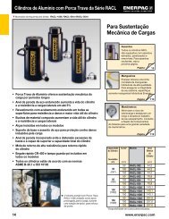
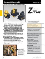
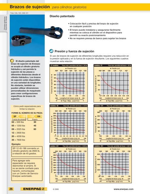
<strong>Brazos</strong> <strong>de</strong> <strong>sujeción</strong> <strong>para</strong> <strong>cilindros</strong> <strong>giratorios</strong><br />
Foto: CAL-122, CAS-121<br />
El diseño patentado <strong>de</strong>l<br />
brazo <strong>de</strong> <strong>sujeción</strong> <strong>de</strong> <strong>Enerpac</strong><br />
se acopla al cilindro giratorio<br />
hidráulico y así permite la<br />
<strong>sujeción</strong> <strong>de</strong> las piezas a<br />
diferentes distancias <strong>de</strong>s<strong>de</strong> el<br />
cilindro hidráulico. Los brazos<br />
<strong>de</strong> <strong>sujeción</strong> están disponibles<br />
en una variedad <strong>de</strong> longitu<strong>de</strong>s.<br />
No obstante, también se<br />
pue<strong>de</strong>n utilizar dimensiones<br />
personalizadas <strong>de</strong> maquinado<br />
<strong>para</strong> crear confi guraciones<br />
específi cas <strong>de</strong> brazos <strong>de</strong><br />
<strong>sujeción</strong>.<br />
26<br />
Cómo pedir espaciadores <strong>para</strong><br />
limitar la rotación<br />
FORME EL NÚMERO DE SU PIEZA:<br />
SP -<br />
- 186<br />
Fuerza <strong>de</strong> amarre Ángulo<br />
02 = 500 lbs 30<br />
05 = 1250 lbs 45<br />
09 = 2025 lbs 60<br />
12 = 2600 lbs<br />
20 = 4200 lbs<br />
35 = 7600 lbs<br />
Ejemplo:<br />
SP-12 45-186 convierte un<br />
cilindro giratorio <strong>de</strong> 2600 lb.<br />
a rotación <strong>de</strong> 45 grados.<br />
Para agregar este<br />
espaciador se requiere<br />
<strong>de</strong>smontar el amarre. Si<br />
no se siente confi ado <strong>para</strong><br />
hacerlo, comuníquese<br />
con un Centro <strong>de</strong> Servicio<br />
<strong>Enerpac</strong> autorizado.<br />
Diseño patentado<br />
-21 mo<strong>de</strong>los Peso máx. permitido <strong>de</strong>l braz = .24 lb<br />
Fuerza <strong>de</strong> <strong>sujeción</strong> (lb) Ë<br />
Á Presión (psi)<br />
5000 3575 2500 2000 1785 1570 1360<br />
600<br />
500<br />
400<br />
300<br />
200<br />
100<br />
2250<br />
2000<br />
0<br />
.98 1.00 1.50 2.50 3.00<br />
CAS Longitud <strong>de</strong> brazo (pulg) Ë CAL<br />
12 Á Flujo Máx. (pulg 6<br />
3 /min)<br />
mo<strong>de</strong>los -92 Peso máx. permitido <strong>de</strong>l brazo = 1.34 lb<br />
Á Presión (psi)<br />
5000 3785 2860 2285 1930 1640 1430<br />
Fuerza <strong>de</strong> <strong>sujeción</strong> (lb) Ë<br />
1750<br />
1500<br />
1250<br />
1000<br />
750<br />
500<br />
250<br />
0<br />
1.77 2.0 2.5 3.0 4.5 4.0 4.5 5.0 5.5 6.0 6.30<br />
CAS Longitud <strong>de</strong> brazo (pulg) Ë CAL<br />
61 Á Flujo Máx. (pulg 36<br />
3 /min)<br />
mo<strong>de</strong>los -201 Peso máx. permitido <strong>de</strong>l brazo = 2.86 lbs<br />
Fuerza <strong>de</strong> <strong>sujeción</strong> (lb) Ë<br />
Á Presión (psi)<br />
5000<br />
4500<br />
3625 3100 2540 2175 1885 1740<br />
4000<br />
3500<br />
3000<br />
2500<br />
2000<br />
1500<br />
1000<br />
500<br />
0<br />
2.17 3.00 4.00 5.00 6.00 7.00<br />
CAS Longitud <strong>de</strong> brazo (pulg) Ë CAL<br />
152 Á Flujo Máx. (pulg 75<br />
3 /min)<br />
© 2008<br />
Colocación fácil y precisa <strong>de</strong>l brazo <strong>de</strong> <strong>sujeción</strong><br />
en cualquier posición<br />
El brazo pue<strong>de</strong> instalarse y asegurarse fácilmente<br />
mientras se coloca el cilindro en el dispositivo <strong>para</strong><br />
permitir su exacto posicionamiento<br />
No se requiere prensa <strong>de</strong> banco <strong>para</strong> sujetar los brazos<br />
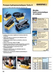
Presión y fuerza <strong>de</strong> <strong>sujeción</strong><br />
El uso <strong>de</strong> brazos <strong>de</strong> <strong>sujeción</strong> <strong>de</strong> diferentes longitu<strong>de</strong>s requiere una reducción en<br />
la presión aplicada y en la fuerza <strong>de</strong> <strong>sujeción</strong> resultante. Los siguientes cuadros<br />
muestran esta relación.<br />
mo<strong>de</strong>los -51 Peso máx. permitido <strong>de</strong>l brazo = .55 lb<br />
Fuerza <strong>de</strong> <strong>sujeción</strong> (lb) Ë<br />
mo<strong>de</strong>los -121 Peso máx. permitido <strong>de</strong>l brazo = 1.54 lbs<br />
Fuerza <strong>de</strong> <strong>sujeción</strong> (lb) Ë<br />
Á Presión (psi)<br />
5000<br />
3000<br />
3625 2900 2465 1960 1450<br />
2500<br />
2000<br />
1500<br />
1000<br />
500<br />
8000<br />
6000<br />
4000<br />
2000<br />
0<br />
2.00 3.00 4.00 5.00 6.00 6.36<br />
CAS Longitud <strong>de</strong> brazo (pulg) Ë CAL<br />
98 Á Flujo Máx. (pulg 49<br />
3 /min)<br />
mo<strong>de</strong>los -351 Peso máx. permitido <strong>de</strong>l brazo = 4.85 lb<br />
Fuerza <strong>de</strong> <strong>sujeción</strong> (lb) Ë<br />
Á Presión (psi)<br />
5000 3850 2700 2150 1775 1425<br />
1250<br />
1000<br />
750<br />
250<br />
0<br />
1.57 2.00 2.50 3.00 3.50 4.00 4.50 5.00<br />
CAS Longitud <strong>de</strong> brazo (pulg) Ë CAL<br />
24 Á Flujo Máx. (pulg 12<br />
3 /min)<br />
Á Presión (bar)<br />
5000 3845 3120 2685 2320 2100<br />
0<br />
2.68 3.00 4.00 5.00 6.00 7.00<br />
CAS Longitud <strong>de</strong> brazo (pulg) Ë CAL<br />
244 Á Flujo Máx. (pulg 122<br />
3 /min)<br />
www.enerpac.com
mo<strong>de</strong>los CAS<br />
G D<br />
E<br />
E<br />
G<br />
C<br />
D2<br />
<strong>Brazos</strong> <strong>de</strong> <strong>sujeción</strong> estándar<br />
L<br />
P<br />
J<br />
A<br />
K1<br />
K2<br />
Q H<br />
F<br />
ø.003" [0,08 mm] A<br />
A<br />
C P<br />
A<br />
J Q<br />
øD1<br />
mo<strong>de</strong>los CAL<br />
G D<br />
mo<strong>de</strong>los CA Bloqueo positivo<br />
Diseño personalizado<br />
Dimensiones en pulgadas [ ]<br />
G<br />
E<br />
K2<br />
Y<br />
F<br />
K1<br />
Y<br />
Dimensiones y opciones Serie CA<br />
C L<br />
J<br />
A<br />
C J<br />
Z Z<br />
<strong>Brazos</strong> <strong>de</strong> <strong>sujeción</strong> largos<br />
H øO<br />
L<br />
115˚-125˚<br />
D2<br />
Fuerza <strong>de</strong> Mo<strong>de</strong>lo<br />
<strong>sujeción</strong><br />
A C D E F G H J L P Q<br />
lbs<br />
▼ <strong>Brazos</strong> <strong>de</strong> <strong>sujeción</strong> estándar<br />
UNC lbs<br />
500 CAS-21 1.60 .38 .392-.396 .63 .40 .76 .50 .250-28 UNF 1.22 .98 .250-20 .1<br />
1250 CAS-51 2.39 .50 .628-.632 .75 .45 1.00 .62 .312-24 UNF 1.89 1.57 .312-18 .8<br />
2025 CAS-92 2.99 .79 .982-.986 .98 .63 1.57 .89 M10x1,25 2.20 1.77 M10x1,5 .7<br />
2600 CAS-121 3.13 .70 .873-.877 1.19 .63 1.39 .82 .375-24 UNF 2.43 2.00 .375-16 1.0<br />
4200 CAS-201 3.71 .95 1.257-1.261 1.18 .82 1.90 1.20 .500-20 UNF 2.76 2.17 .500-13 1.0<br />
7600 CAS-351 4.65 1.38 1.494-1.498 1.58 1.16 2.76 1.24 .625-18 UNF 3.27 2.68 .625-11 3.0<br />
▼ <strong>Brazos</strong> <strong>de</strong> <strong>sujeción</strong> largos<br />
500 CAL-22 2.85 .30 .392-.396 .63 .40 .76 .44 M6x1 3.25 – – .2<br />
1250 CAL-52 5.81 .50 .628-.632 .75 .45 1.00 .55 M8x1 5.31 – – 1.0<br />
2025 CAL-92 7.09 .79 .982-.986 .98 .63 1.57 .71 M10x1,25 6.30 – – 1.2<br />
2600 CAL-122 7.06 .70 .873-.877 1.19 .63 1.39 .72 M10x1,5 6.36 – – 1.5<br />
4200 CAL-202 7.95 .95 1.257-1.261 1.18 .82 1.90 1.00 M12x1,25 7.00 – – 1.5<br />
7600 CAL-352 8.47 1.38 1.494-1.498 1.58 1.33 2.76 1.18 M16x1,50 7.09 – – 4.2<br />
Fuerza <strong>de</strong> Mo<strong>de</strong>lo A C D1 D2 E G J K1 K2 P Q<br />
<strong>sujeción</strong><br />
lbs<br />
ø UNF UNF UNF lbs<br />
▼ <strong>Brazos</strong> <strong>de</strong> <strong>sujeción</strong> <strong>de</strong> bloqueo positivo<br />
1000 CA-540 2.84 .71 .749-.750 .63-18 1.18 1.26 .313-24 .75 .39 1.57 .313-24 1.2<br />
2000 CA-1050 3.27 .75 .878-.879 .75-16 1.18 1.38 .313-24 .71 .39 1.97 .375-24 1.2<br />
8500 CA-3070 5.04 1.38 1.377-1.378 1.25-12 1.85 2.32 .313-24 1.26 .67 2.76 .625-18 5.0<br />
D1<br />
C D11) Fuerza <strong>de</strong><br />
<strong>sujeción</strong><br />
lbs<br />
ø<br />
D2<br />
ø<br />
E F G H J K1 K2 L O<br />
ø<br />
P<br />
ø<br />
R<br />
▼ <strong>Brazos</strong> <strong>de</strong> <strong>sujeción</strong> <strong>de</strong> diseño personalizado2) (Dimensiones <strong>de</strong> maquinado recomendadas)<br />
500 .61 .393-.394 .495-.497 .63 .06-.12 .79 .37 M5x0,8 .122-.138 .33 .98-1.10 .22 .49 .22<br />
1250 .79 .623-.631 .727-.729 .75 .06-.12 1.18 .53 M6x1,0 .161-.177 .39 1.38-1.57 .26 .43 .26<br />
2025 1.18 .984-.985 1.096-1.100 .98 .06-.12 1.57 .87 M8x1,25 .154-.165 .49 2.17-2.36 .35 .55 .35<br />
2600 1.12 .8756-.8766 1.002-1.006 1.18 .06-.12 1.38 .70 .375-24 UNF .272-.287 .50 2.05-2.25 .39 .63 .31<br />
4200 1.38 1.260-1.261 1.398-1.402 1.18 .06-.12 2.36 .98 M10x1,5 .201-.217 .59 2.44-2.64 .43 .67 .43<br />
7600 1.57 1.496-1.497 1.634-1.638 1.57 .06-.12 2.76 1.18 M10x1,5 .193-.209 .79 3.15-3.35 .43 .67 .43<br />
1) La aspereza <strong>de</strong> la superfi cie <strong>de</strong> D1 <strong>de</strong>be ser <strong>de</strong> 63 micropulgadas.<br />
2) No apto <strong>para</strong> ser utilizado con <strong>cilindros</strong> <strong>de</strong> bloqueo positivo.<br />
© 2008 27<br />
E<br />
øP<br />
H<br />
F<br />
(únicamente <strong>para</strong><br />
mo<strong>de</strong>los SU, SL, ST y SC)]<br />
R<br />
Fuerza: 500 - 8500 lbs<br />
Presión: 500 - 5000 psi<br />
E Swing cylin<strong>de</strong>rs<br />
F Bras <strong>de</strong> bridage<br />
D Spannarme<br />
Opciones<br />
Manómetros<br />
154 �<br />
Válvulas <strong>de</strong><br />
control <strong>de</strong> fl ujo<br />
138 �<br />
Importante<br />
No sobrepase el fl ujomáximo<br />
<strong>de</strong> aceite.<br />
Si se sobrepasan los límites <strong>de</strong><br />
fl ujo máximo, el mecanismo <strong>de</strong><br />
in<strong>de</strong>xación <strong>de</strong>l cilindro giratorio<br />
pue<strong>de</strong> resultar dañado <strong>de</strong> forma<br />
permanente.<br />
Mecanismo <strong>de</strong><br />
in<strong>de</strong>xación<br />
Cuando se diseñan brazos <strong>de</strong><br />
<strong>sujeción</strong> personalizados, los<br />
límites <strong>de</strong> caudal <strong>de</strong>ben reducirse<br />
aún más. Este valor <strong>de</strong>be ser<br />
proporcional a la masa y al centro<br />
<strong>de</strong> gravedad <strong>de</strong>l brazo <strong>de</strong> <strong>sujeción</strong>.<br />
Ejemplo:<br />
Si la masa <strong>de</strong>l brazo es el doble<br />
<strong>de</strong> la <strong>de</strong>l brazo largo, los límites <strong>de</strong><br />
fl ujo <strong>de</strong>ben reducirse un 50%.<br />
Cilindros <strong>giratorios</strong><br />
Soportes <strong>de</strong> trabajo<br />
Cilindros lineales<br />
Bombas<br />
hidráulicas<br />
Válvulas<br />
Componentes<br />
<strong>de</strong>l sistema<br />
Páginas amarillas