MULTÃMETRO DIGITAL PARA AUTOMÃVILES ... - Ega Master
MULTÃMETRO DIGITAL PARA AUTOMÃVILES ... - Ega Master
MULTÃMETRO DIGITAL PARA AUTOMÃVILES ... - Ega Master

Create successful ePaper yourself
Turn your PDF publications into a flip-book with our unique Google optimized e-Paper software.
MANUAL DE INSTRUCCIONES<br />
OPERATING INSTRUCTIONS<br />
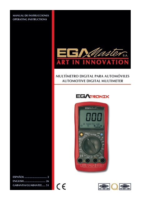
MULTÍMETRO <strong>DIGITAL</strong> <strong>PARA</strong> AUTOMÓVILES<br />
AUTOMOTIVE <strong>DIGITAL</strong> MULTIMETER<br />
ESPAÑOL................................ 2<br />
ENGLISH............................... 26<br />
GARANTIA/GUARANTEE...... 51
ESPAÑOL<br />
CONTENIDO<br />
Información general............................................................................................... 3<br />
Reglas para una operación segura........................................................................... 4<br />
Guía para un seguro servicio del automóvil............................................................ 5<br />
Símbolos eléctricos internacionales........................................................................ 6<br />
La estructura del medidor....................................................................................... 7<br />
Interruptor rotatorio................................................................................................ 7<br />
Funciones de los botones....................................................................................... 8<br />
Símbolos de la pantalla.......................................................................................... 8<br />
Operación de medida............................................................................................. 9<br />
A. DC prueba de voltaje......................................................................................... 9<br />
B. AV prueba de voltaje........................................................................................ 10<br />
C. DC prueba de corriente.................................................................................... 11<br />
D. Prueba de resistencia....................................................................................... 12<br />
E. Prueba de diodo............................................................................................... 13<br />
F. Prueba de continuidad...................................................................................... 14<br />
G. Medida de la batería de 12V............................................................................ 14<br />
H. Medida de la temperatura................................................................................ 15<br />
I. Medida de frecuencia........................................................................................ 16<br />
J. Medición del ciclo de servicio........................................................................... 17<br />
K. Prueba de parada momentánea (Dwell) ........................................................... 18<br />
L. Tacómetro (velocidad de rotación) prueba “RPMX10”...................................... 19<br />
M. Operación del modo HOLD............................................................................ 19<br />
Especificaciones generales.................................................................................... 20<br />
Especificaciones exactas....................................................................................... 20<br />
A. Voltaje DC....................................................................................................... 20<br />
B. Voltaje AC....................................................................................................... 21<br />
C. Corriente DC................................................................................................... 21<br />
D. Resistencia....................................................................................................... 21<br />
E. Diodo ........................................................................................................ 21<br />
F. Prueba de continuidad...................................................................................... 22<br />
G. Batería 12V...................................................................................................... 22<br />
H. Temperatura.................................................................................................... 22<br />
I. Frecuencia ........................................................................................................ 22<br />
2
J. Ciclo de trabajo..................................................................................................... 23<br />
K. Prueba Dwell....................................................................................................... 23<br />
L. Prueba de tach ( Velocidad de rotación).............................................................. 23<br />
Mantenimiento......................................................................................................... 23<br />
A. Servicios generales............................................................................................... 24<br />
B . Sustitución de los fusibles ................................................................................... 24<br />
C. Sustitución de la batería....................................................................................... 25<br />
INFORMACIÓN GENERAL<br />
Este manual de instrucciones contiene información sobre la seguridad y las precauciones<br />
a tener en cuenta a la hora de utilizar este medidor. Por favor, lea la información relevante<br />
cuidadosamente y observe todas las notas y advertencias con atención.<br />
Advertencia!<br />
Para evitar descargas eléctricas o lesiones personales, lea cuidadosamente las “Información de<br />
seguridad” y “Reglas para la operación segura” antes de utilizar el medidor.<br />
El multímetro digital para automóviles modelo COD. 51259 (de aquí en adelante será<br />
identificado como “el medidor”) con pantalla de 1999 conteos, un medidor de rango manual de<br />
3-1/2 dígitos. Posee un diseño único con pantalla LCD extra grande, pantalla con conexión de<br />
prueba, protección contra sobrecarga y diseño único. Por esta razón, surge como un medidor<br />
eléctrico con un rendimiento altamente destacado para una operación más segura que otros<br />
medidores. Además del DWELL, el tacómetro y la retención de datos “HOLD”, el medidor puede<br />
ser utilizado para medir el voltaje AC, el voltaje DC, corriente DC, resistencia, temperatura, batería,<br />
ciclo de trabajo, frecuencia, diodo y continuidad.<br />
DESEMBALAJE<br />
Abra la caja empaquetada y saque el medidor. Compruebe los siguientes elementos<br />
cuidadosamente para comprobar si falta algo o se aprecia algún cambio:<br />
Item Descripción Cantidad<br />
1 Manual de instrucciones 1 pieza<br />
2 Cable de prueba 1 par<br />
3<br />
Prueba de temperatura en el punto de<br />
contacto<br />
1 pieza<br />
4 funda 1 pieza<br />
5 Batería de 9V/NEDA 1604, 6F22 ó 0066P) 1 pieza<br />
En caso de encontrar alguna falta o daño, por favor póngase en contacto con su distribuidor<br />
inmediatamente.<br />
3
INFORMACIÓN DE SEGURIDAD<br />
Este medidor cumple con las normas ICE61010: en grado de contaminación 2, categoría de<br />
sobretensión (CAT. II 1000V,CAT.III 600V) y doble aislamiento.<br />
CAT II: nivel local, electrodomésticos, EQUIPO PORTATIL etc., con menores sobretensiones<br />
transitorias que CAT. IV<br />
CAT.III: Nivel de distribución. Instalación fija, con menores sobretensiones que CAT.IV<br />
Use este medidor solo como se especifica en el manual, si no la protección que proporciona el<br />
medidor puede verse reducida.<br />
Los símbolos eléctricos internacionales usados en el medidor y en éste manual de instrucciones<br />
están explicados en la página 6.<br />
REGLAS <strong>PARA</strong> UNA OPERACIÓN SEGURA<br />
Advertencia!<br />
Para evitar descargas eléctricas o lesiones personales, y para evitar posibles daños al medidor<br />
o al equipo a prueba, se adhieren las siguientes reglas:<br />
• Antes de usar el medidor inspeccione la caja. No use el medidor si está dañado o si la<br />
carcasa(o parte de la carcasa) esta movida. Busque grietas o plástico perdido. Preste atención al<br />
aislamiento alrededor de los conectores.<br />
• Inspeccione los cables por si el aislamiento está dañado o el metal expuesto. Chequear la<br />
continuidad en la conexión de prueba. En caso de que haya daños, reemplace los cables dañados<br />
solo por un modelo idéntico o de las mismas especificaciones eléctricas antes de usar el medidor.<br />
• Cuando esté usando la conexión de prueba, mantenga sus dedos detrás de las protecciones<br />
• No aplicar más voltaje del nominal, indicado en el medidor, entre los terminales o entre<br />
cualquier terminal y la toma de tierra.<br />
• Para evitar lastimarse, nunca intente meter una tensión eficaz de mayor de 60 V en DC o 30<br />
V en AC.<br />
• Usar los terminales apropiados, función y rango para sus mediciones.<br />
• El interruptor rotatorio debería posicionarse en la posición adecuada y no debe efectuarse<br />
ninguna conversión de rango cuando se está efectuando la medida para prevenir daños en el<br />
medidor.<br />
• Desconecte la alimentación del circuito y descargue todos los capacitores de alta tensión<br />
antes de la prueba de resistencia, continuidad y diodos.<br />
• Antes de medir la corriente, probar si el fusible está bien. Antes de conectar el medidor en<br />
serie, desconecte la energía del circuito.<br />
• Si el valor de la corriente a ser medido es desconocido, utilice el valor máximo de<br />
medición y reduzca el rango paso a paso hasta que la lectura sea satisfactoria.<br />
• Reemplace la batería tan pronto como el indicador de la batería lo indique. Con la<br />
batería baja, el medidor podría producir lecturas que pueden conducir a descargas eléctricas y<br />
lesiones personales.<br />
• Al reparar el medidor, use solo el mismo modelo o idénticas especificaciones para las<br />
partes reemplazadas.<br />
• El circuito interno del medidor no debe ser alterado para evitar daños en el medidor y<br />
ningún accidente.<br />
4
• Para limpiar la superficie del medidor, utilice un paño suave y un detergente suave. No<br />
utilice abrasivos disolventes para evitar que la superficie del medidor sufra daños<br />
• Apague el medidor cuando no esté en uso y retire la batería cuando no se vaya a utilizar<br />
durante un largo periodo de tiempo.<br />
• Revise constantemente el estado de la batería cuando haya sido usado durante un tiempo ya<br />
que podrían aparecer fugas. Remplace la batería tan pronto como aparezcan fugas, puede dañar el<br />
medidor.<br />
• No utilice ni guarde el medidor en un ambiente de alta temperatura o humedad, ambientes<br />
explosivos, inflamables o campos magnéticos fuertes. La fundición del medidor puede deteriorarse<br />
si se humedece.<br />
• El medidor es adecuado para su uso en interiores.<br />
GUÍA <strong>PARA</strong> UN SEGURO SERVICIO DEL AUTOMÓVIL<br />
Advertencia!<br />
Como se instalan airbags en algunos automóviles, debe prestar atención a las advertencias<br />
que se especifican en el manual de servicio del automóvil cuando esté trabajando alrededor de<br />
los componentes y los cables de los airbags, puesto que en cualquier descuido podría abrirse<br />
un airbag y causar daños personales. Notar que el airbag se mantendrá abierto durante algunos<br />
minutos hasta que se cierre el bloqueo(o incluso cuando se desconecte la batería automotriz) el<br />
cual es conducido por una reserva de energía especial.<br />
Para prevenir un accidente que cause cualquier daño personal o cualquier daño al automóvil o<br />
a cualquiera de sus medidores, por favor lea las guías de seguridad que se aparecen a continuación<br />
y pruebe el procedimiento con seriedad:<br />
• Levar gafas de protección las cuales cumplan con los requerimientos de seguridad<br />
• Manejar el automóvil en un lugar bien ventilado, para prevenir la inhalación de cualquier<br />
toxico o gases de escape.<br />
• Mantener tus propias herramientas e instrumentos de prueba lejos de todos los componentes<br />
de calefacción del aparato en operación.<br />
• Asegurar que el automóvil haya parado (transición automática) o ponerlo en punto muerto<br />
(transición manual) y estar seguro de que esté el freno echado y las ruedas bloqueadas.<br />
• No poner ninguna herramienta en la batería del automóvil la cual causará un cortocircuito<br />
en los electrodos y puede llevar a daños personales o daños de la batería o de la herramienta.<br />
• Fumar o encender una llama cerca del automóvil está prohibido<br />
• Prestar atención a la bobina de encendido, una ignición del cable o una bujía porque estos<br />
componentes están prohibidos con altos voltajes cuando el automóvil esta en operación.<br />
• Al conectar o desconectar un componente electrónico, cerrar el interruptor de encendido.<br />
• Prestar atención en las advertencias, notas y procedimientos en servicio del fabricante.<br />
Es posible comprobar la exactitud y la plenitud de la información, de la cual no asumimos<br />
responsabilidades.<br />
5
A. El manual de instrucciones ha sido creado a partir de la información en servicio.<br />
1. Contactar con los distribuidores locales de los componentes de automoción.<br />
2. Contactar con los minoristas de los componentes de automoción.<br />
3. Consulte en las bibliotecas locales para consultar la edición de cualquier libro a fin de<br />
proveerle a usted con la última información.<br />
B. Antes del diagnóstico de cualquier problema abrir la tapa del aparato para hacer una<br />
inspección visual. Encontrará la causa de muchos de los problemas para solventarlos<br />
1. ¿Ha llevado a arreglar el coche hace poco? ¿Ha tenido el mismo problema varias veces en el<br />
mismo lugar?<br />
2. No intente encontrar algún cortocircuito. Revise las mangueras y los cables donde es poco<br />
probable encontrar donde se ubican otros problemas.<br />
3. Revise cualquier problema con el depurador de agua o el sistema de tubos.<br />
4. Revise cualquier daño de cualquier sensor o el engranaje de transmisión.<br />
5. Revise el cable de encendido: cualquier de cualquier terminal, grieta en cualquier bujía, o<br />
rotura de la protección del cable de encendido.<br />
6. Revise todo las mangueras de vacío: cualquier línea recta, encogimiento, curva grieta,<br />
fractura o daño.<br />
7. Revise los cables: cualquier conexión con bordes en arista, conexiones de superficies<br />
calientes (como el colector de escape), encogimiento, quemaduras o arañazos en las protecciones<br />
o conexiones en línea recta.<br />
8. Revise las conexiones de los circuitos: corrosión en los pines, curvas, daños, posición de las<br />
conexiones inapropiada o daños en el cable del electrodo.<br />
SÍMBOLOS ELÉCTRICOS INTERNACIONALES<br />
AC (Corriente Alterna)<br />
DC (Corriente Continua)<br />
Toma a tierra<br />
Con doble aislamiento<br />
Estado de la batería<br />
Fusible<br />
Advertencia. Consulte el manual de<br />
instrucciones<br />
Conforme a las normas de la Unión Europea<br />
6
LA ESTRUCTURA DEL MEDIDOR (VER FIGURA 1)<br />
1. Pantalla LCD<br />
2. Botón para guardar los datos<br />
3. Interruptor rotatorio<br />
4. Terminales de entrada<br />
5. Botón de encendido<br />
(figura 1)<br />
INTERRUPTOR ROTATORIO<br />
A continuación se indica la tabla para obtener la información sobre las funciones de la ruleta.<br />
Posición de la ruleta<br />
Función<br />
Medición del voltaje DC<br />
Ω<br />
Medición del voltaje AC<br />
Medida de la resistencia<br />
Prueba de diodos<br />
Prueba de continuidad, Unidad Ω<br />
Medida de la corriente DC<br />
12V<br />
Medida de la batería<br />
ºC Medida de la temperatura, Unidad ºC<br />
kHz<br />
Medida de la frecuencia, Unidad: kilohercio<br />
Duty%<br />
Medida del ciclo en servicio<br />
Prueba del DWELL, Unidad: grados<br />
Prueba de tacómetro (lectura en pantalla X 10) Unidad: rmp<br />
7
FUNCIONES DE LOS BOTONES<br />
A continuación se indica la tabla para obtener información sobre las funciones de los botones.<br />
Botón<br />
HOLD<br />
Operación realizada<br />
Gire el encendido y apagado.<br />
Pulse HOLD una vez que este en el modo hold<br />
Presione HOLD de nuevo para salir del modo hold y se mostrará el<br />
valor actual.<br />
En el modo Hold,<br />
aparecerá.<br />
SÍMBOLOS DE LA PANTALLA (VER FIGURA 2)<br />
(figura 2)<br />
1<br />
La batería esta baja.<br />
Advertencia: Para evitar lecturas falsas<br />
las cuales podrían llevar a un electroshock<br />
o daños personales, remplace la batería<br />
tan pronto como el indicador de la batería<br />
aparezca.<br />
2 Indica lectura negativa<br />
3 Prueba de diodo<br />
4 Prueba de continuidad<br />
5 Retención de datos esta activo<br />
6<br />
Conecte los cables de prueba<br />
Indicador de prueba de conexión entre<br />
diferentes terminales.<br />
8
PRUEBA BÁSICA DE MEDIDOR<br />
A. DC PRUEBA DE VOLTAJE (VER FIGURA 3)<br />
(figura 3)<br />
Advertencia!<br />
Para evitar daños personales al medidor por un electroshock, por favor no intente medir<br />
voltajes mayores de 1000V aunque la lectura podría ser obtenida.<br />
Por favor tenga cuidado especialmente cuando se midan voltajes altos para evitar un<br />
electroshock.<br />
Los rango de voltaje DC son: 200mV,2V,20V, 200V y 1000V<br />
Para medir voltaje DC conectar el medidor como sigue:<br />
1. Introduzca el cable de prueba rojo en el terminal V y el cable de prueba negro en el<br />
terminal COM<br />
2. Posicione la ruleta en la posición de medida apropiada en .<br />
3. Conecte los cables de prueba entre los extremos del objeto medido.<br />
El valor medido aparece en la pantalla.<br />
Nota<br />
• Si el valor del voltaje a ser medido es desconocido use la posición de medida máxima<br />
(1000V) y reduzca el rango paso a paso hasta que la lectura satisfactoria sea obtenida.<br />
• Un “1” en la pantalla LCD indica que el rango seleccionado está sobrecargado, es necesario<br />
seleccionar un rango mayor para obtener una lectura correcta.<br />
• En cada rango, el medidor tiene una entrada de impedancia aproximada de 10 MΩ. Este<br />
efecto de carga puede causar errores en las medidas en circuitos con impedancias altas. Si la<br />
impedancia del circuito es menor o igual que 10kΩ, el error es despreciable (0,1 o menor).<br />
• Cuando la medida del voltaje DC ha sido completado, desconectar la conexión entre los<br />
cables de prueba y el circuito sometido a prueba.<br />
9
B. AV PRUEBA DE VOLTAJE (VER FIGURA 4)<br />
(figura 4)<br />
Advertencia!<br />
Para evitar daños personales al medidor por un electroshock, por favor no intente medir<br />
voltajes mayores de 1000V aunque la lectura podría ser obtenida.<br />
Por favor tenga cuidado especialmente cuando se midan voltajes altos para evitar un<br />
electroshock.<br />
Los rangos de voltaje de AC son: 200V y 750V.<br />
Para medir voltaje de AC, conectar el medidor como sigue:<br />
1. Introduzca el cable de prueba rojo en el terminal V y el cable de prueba negro en el<br />
terminal COM.<br />
2. Posicione la ruleta en la posición de medida apropiada en .<br />
3. Conecte los cables de prueba entre los extremos del objeto medido.<br />
El valor medido aparece en la pantalla. Es el valor efectivo de la onda sinusoide (respuesta de<br />
valor medio).<br />
Nota<br />
• Si el valor de voltaje a ser medido es desconocido use la posición de medida máxima<br />
(1000V) y reduzca el rango paso a paso hasta obtener una medida satisfactoria.<br />
• Un “1” en la pantalla LCD indica que el rango seleccionado está sobrecargado, es necesario<br />
seleccionar un rango mayor para obtener una lectura correcta.<br />
• En cada rango, el medidor tiene una entrada de impedancia aproximada de 10 MΩ. Este<br />
efecto de carga puede causar errores en las medidas en circuitos con impedancias altas. Si la<br />
impedancia del circuito es menor o igual que 10kΩ, el error es despreciable (0,1 o menor).<br />
• Cuando la medida del voltaje AC ha sido completado, desconecte la conexión entre los<br />
cables de prueba y el circuito sometido a prueba.<br />
10
C. DC PRUEBA DE CORRIENTE (VER FIGURA 5)<br />
(figura 5)<br />
Advertencia!<br />
Antes de conectar el medidor en serie con el circuito probado, desconecte dicho circuito.<br />
Si se quema el fusible durante la medida, el medidor podría dañarse o el operador podría<br />
resultar herido. Usar los terminales, la función y el rango apropiados para la medida. Cuando<br />
los cables de prueba son conectados a los terminales de corriente, No ponerlos en paralelo con<br />
ningún circuito, si no se quemará el fusible o el medidor resultará dañado.<br />
The current ranges are: 200mA and 10A.<br />
Los rangos de corriente son: 200mA y 10ª<br />
Para medir la corriente DC, conecte el medidor como sigue:<br />
1. Inserte el cable rojo de prueba al o al terminal A y el cable negro de prueba al<br />
terminal COM.<br />
2. Set the rotary switch to an appropriate measurement position in .<br />
3. Connect the test leads in serial to the object being measured.<br />
The measured value shows on the display.<br />
Nota<br />
• Si el valor de la corriente a ser medido es desconocido, use la posición de medida máximo<br />
(10A) y el terminal 10A, y reduzca el rango paso a paso hasta que una lectura satisfactoria sea<br />
obtenida.<br />
• Cuando la medida de la corriente DC ha sido completada, desconecte la conexión entre los<br />
cables de prueba y el circuito sometido a prueba<br />
• Cuando se midan 5A ~ 10A: Para mediciones continuas de ≤10 segundos e intervalos<br />
mayores de tiempo entre 2 medidas mayores de 15 minutos.<br />
11
D. PRUEBA DE RESISTENCIA (VER FIGURA 6)<br />
(figura 6)<br />
Advertencia!<br />
Para evitar daños al medidor u otro aparato bajo prueba, desconecte la energía del circuito y<br />
descargue todos los condensadores de alto voltaje antes de realizar la medición de resistencia<br />
Para evitar daños personales, nunca intente introducir un voltaje efectivo de más de 60V en<br />
DC o 30V en AC.<br />
Los rangos de resistencia DC son: 200Ω,2kΩ, 20k, 200kΩ, 2MΩ y 20 MΩ<br />
Para medir la resistencia DC conectar el medidor como sigue:<br />
1. Introduzca el cable de prueba rojo en el terminal Ω y el cable de prueba negro en el<br />
terminal COM.<br />
2. Posicione la ruleta en la posición de medida apropiada en rango Ω<br />
3. Conecte los cables de prueba entre los extremos del objeto medido.<br />
El valor medido aparece en la pantalla.<br />
Nota<br />
• Los cables de prueba pueden aumentar el error entre 0,1Ω y 0,2Ω a la medida de la<br />
resistencia. Para obtener lecturas con precisión con bajas resistencias, este es el rango de 200Ω,<br />
cortocircuite la entrada de los terminales de antemano y anote la lectura obtenida (esta lectura es<br />
llamada X). (X) es la resistencia adicional de los cables de prueba.<br />
Entonces use la ecuación:<br />
Valor de la resistencia medida (Y)-(X)= Precisión de la lectura de la resistencia.<br />
• Cuando la lectura de la resistencia es ≥ 0.5Ω en condición de cortocircuito, por favor revise<br />
que los cables de prueba no se hayan aflojado u otras razones.<br />
• Para resistencias altas (>1MΩ), es normal que tarde varios segundos en obtener lecturas<br />
estables, y es mejor elegir cables de prueba más cortos.<br />
• Cuando no haya entradas, por ejemplo en condiciones de circuito abierto, la pantalla del<br />
medidor mostrará “1”<br />
• Cuando la medida de la resistencia haya sido completada. Desconecte la conexión entre los<br />
cables de prueba y el circuito sometido a prueba.<br />
12
E. PRUEBA DE DIODO (VER FIGURA 7)<br />
(figura 7)<br />
Advertencia!<br />
Para evitar posibles daños en el medidor y el dispositivo sometido a prueba, desconecte la<br />
energía del circuito y descargue todos los condensadores de alto voltaje antes de realizar la<br />
medición de resistencia<br />
Para evitar daños personales, nunca intente introducir un voltaje efectivo de más de 60V<br />
en DC o 30V en AC.<br />
Use la prueba de diodos para revisar los diodos, transistores y otros dispositivos<br />
semiconductores. La prueba de diodo envía una corriente a través de la unión semiconductora,<br />
entonces mide la caída de tensión a través de la unión. Una buena unión de silicio cae entre 0,5V<br />
y 0.8V.<br />
Para probar el diodo fuera de un circuito, conecte el medidor como sigue:<br />
1. Introduzca el cable de prueba rojo en el terminal y el cable negro de prueba en el<br />
terminal COM.<br />
2. Coloque la ruleta en .<br />
3. Para las lecturas de caída de tensión en cualquiera de los componentes semiconductores,<br />
coloque el cable rojo de prueba en el ánodo del componente y coloque el cable de prueba negro<br />
en el cátodo del componente. La polaridad del cable rojo de prueba es “+” mientras que el negro<br />
es “-“<br />
El valor medido aparece en la pantalla.<br />
Nota<br />
• En un circuito, un buen diodo debería todavía producir una caída de tensión en la lectura<br />
entre 0.5 y 0.8V; sin embargo, la caída en la tensión invertida puede variar dependiendo de la<br />
resistencia de otros caminos entre la punta del medidor.<br />
• Conecte los cables de prueba a los terminales apropiados como se dijo anteriormente para<br />
evitar errores en la pantalla<br />
• El voltaje del circuito abierto esta alrededor de 2.7V cuando se prueba el diodo<br />
• En la pantalla LCD aparecerá un “1” indicando que el circuito está abierto o conexión de<br />
polaridad errónea.<br />
• Cuando la prueba del diodo ha sido completada, desconecte la conexión entre los cables de<br />
prueba y el circuito sometido a prueba.<br />
13
F. PRUEBA DE CONTINUIDAD (VER FIGURA 7)<br />
Advertencia!<br />
Para evitar posibles daños en el medidor y el dispositivo sometido a prueba, desconecte la<br />
energía del circuito y descargue todos los condensadores de alto voltaje antes de realizar la<br />
medición de resistencia.<br />
Para evitar daños personales, nunca intente introducir un voltaje efectivo de más de 60V en<br />
DC o 30V en AC.<br />
Para hacer la prueba de continuidad, conecte el medidor como se indica a continuación:<br />
1. Introduzca el cable de prueba rojo en el terminal y el cable negro de prueba en el<br />
terminal COM.<br />
2. Coloque la ruleta en .<br />
3. Conecte los cables de prueba entre el objeto a ser medido.<br />
• El timbre no suena cuando el valor de la resistencia es >100Ω. El circuito esta desconectado<br />
• El timbre suena continuamente cuando la resistencia vale ≤10Ω. El circuito está en buenas<br />
condiciones<br />
• El timbre podría o no podría sonar cuando el valor de la resistencia está entre 10Ω y 100Ω<br />
4. El valor más cercano del circuito probado se muestra en la pantalla, las unidades son Ω.<br />
Nota<br />
• El voltaje del circuito abierto es aproximadamente 3V<br />
• Cuando el test de continuidad ha sido completado, desconectar la conexión entre los cables<br />
de prueba y el circuito sometido a prueba.<br />
G. MEDIDA DE LA BATERÍA DE 12V (VER FIGURA 8)<br />
(figura 8)<br />
Advertencia!<br />
Para evitar daños personales, nunca intente introducir un voltaje efectivo de más de 60V en<br />
DC o 30V en AC.<br />
Para probar la batería, proceder como sigue:<br />
14
1. Inserte el cable rojo de prueba en el terminal y el cable de prueba negro en el<br />
terminal COM.<br />
2. Coloque al ruleta en 12V.<br />
3. Conecte Los cables de prueba entre los extremos del objeto a ser medido. El cable de<br />
prueba rojo al positivo y cable de prueba negro a la polaridad negativa.<br />
4. El valor medido aparecerá en la pantalla en unidades de V.<br />
Nota<br />
• El medidor solo es aplicable a medidas menores de 20V batería fuera de servicio. Para<br />
medir la batería en servicio, es necesario aumentar la carga de trabajo y la carga integrada del<br />
medidor<br />
• La resistencia de carga que ha sido integrada en el medidor es 120Ω/2W El valor medido<br />
que aparece en la pantalla es el valor de la batería cargada<br />
• Cuando la prueba de la batería ha sido completada, desconecte la conexión entre el cable<br />
de prueba y el circuito sometido a prueba.<br />
H. MEDIDA DE LA TEMPERATURA (VER FIGURA 9)<br />
(figura 9)<br />
Advertencia!<br />
Para evitar daños personales, nunca intente introducir un voltaje efectivo de más de 60V en<br />
DC o 30V en AC.<br />
Para medir la temperatura, conecte el medidor como se indica:<br />
1. Inserte el cable de prueba rojo en el terminal y el cable de prueba negro en el<br />
terminal COM<br />
2. Coloque la ruleta en ºC<br />
3. Coloque la prueba de la temperatura en el interior o en el exterior del objeto que va a ser<br />
medido<br />
4. El valor medido se muestra en la pantalla, la unidad es ºC.<br />
15
Nota<br />
• Por favor elija la prueba de temperatura correcta. El cable de prueba de temperatura<br />
incluido solo puede medir por encima de 250 ºC. Necesitará seleccionar otro cable de<br />
temperatura para cualquier medición mayor a 250 ºC<br />
• El medidor muestra un “1” cuando no hay señal de entrada<br />
• El medidor muestra el valor de temperatura interna más cercana cuando los terminales de<br />
entrada con cortados.<br />
• Cuando la prueba de temperatura ha sido completada, desconecte la conexión entre la<br />
prueba de temperatura y el circuitos sometido aprueba.<br />
I. MEDIDA DE FRECUENCIA (VER FIGURA 10)<br />
(figura 10)<br />
Advertencia!<br />
Para evitar daños personales, nunca intente introducir un voltaje efectivo de<br />
DC o 30V en AC.<br />
más de 60V en<br />
Para medir la frecuencia conectar el medidor como se indica:<br />
1. Inserte el cable de prueba rojo en el terminal Hz y el cable de prueba negro en el terminal<br />
COM.<br />
2. Coloque la ruleta en 2kHz.<br />
3. Coloque la prueba de la temperatura en el interior o en el exterior del objeto que va a ser<br />
medido<br />
4. El valor medido se muestra en la pantalla, la unidad es kHz.<br />
Nota<br />
• Este método de medida es aplicable a entradas de alcance menores de
J. MEDICIÓN DEL CICLO DE SERVICIO CYLE (VER FIGURA 11)<br />
(figura 11)<br />
Advertencia!<br />
Para evitar daños personales, nunca intente introducir un voltaje efectivo de más de 60V en<br />
DC o 30V en AC.<br />
Para medir el ciclo de servicio, conecte el medidor como sigue<br />
5. Inserte el cable de prueba rojo en el terminal Hz y el cable de prueba negro en el terminal<br />
COM.<br />
6. Coloque la ruleta en DUTY%.<br />
7. Coloque Los cables de prueba entre los extremos del objeto que van a ser medidos<br />
8. El valor medido se muestra en la pantalla, la unidad es%.<br />
Nota<br />
• Este método de medida es aplicable a entradas de alcance menores de
K. PRUEBA DE <strong>PARA</strong>DA MOMENTÁNEA (DWELL) (VER LA FIGURA 12)<br />
(figura 12)<br />
En el pasado era muy importante revisar la parada momentánea del interruptor de freno del<br />
sistema de ignición. La prueba de parada momentánea hace referencia a la duración cuando el<br />
interruptor de corte se mantiene parado cuando la leva se mueve. Ahora como los automóviles<br />
se encienden electrónicamente, no se tarda mucho en ajustar el DWELL. Además la prueba del<br />
DWELL puede ser empleada para probar el solenoide mezclado controlado (mixed controlled<br />
solenoid)<br />
(Por ejemplo, GM carburador de retroalimentación)<br />
1. Coloque la ruleta en DWELL.<br />
2. Como se indica en los terminales de conexión del LCD, introducir el cable de prueba rojo<br />
en el terminal y en cable de prueba negro en el terminal COM. Conectar los terminales como<br />
se muestra.<br />
• Si el interruptor de corte del sistema de ignición es revisado conecte el cable de prueba<br />
rojo al terminal negativo primario del cable de encendido. (Referirse el manual de servicio del<br />
automóvil para la posición específica)<br />
• Si la retroalimentación del carburador GM es probado, conecte el cable rojo al terminal de<br />
tierra o al ordenador de a bordo del solenoide (Consulte con el manual de servicio del automóvil<br />
para la posición específica)<br />
• Si el DWELL de un equipo arbitrario de ON/OFF es revisado, conecte el cable de prueba<br />
rojo al terminal del equipo, fijado con un interruptor ON/OFF.<br />
3. Conecte el cable de prueba negro a una buena toma de tierra del automóvil<br />
4. Lea el arranque del dwell del automóvil probado directamente de la pantalla<br />
18
L. ENGINE TACH (ROTATION SPEED) TESTING “RPMX10” (SEE FIGURE 13)<br />
(figura 13)<br />
El RPM se refiere a la frecuencia de rotación por minuto del eje principal del aparato.<br />
1. Ponga la ruleta en RPMx10.<br />
2. Como se indica en los terminales de conexión, introduzca el cable de prueba rojo en el<br />
terminal y el cable de prueba negro en el terminal COM. Seleccionar un número apropiado de<br />
cilindros. Conectar los terminales que se van a probar como se muestra.<br />
• Si se emplea en el automóvil un sistema de encendido DIS sin cuadro de distribución,<br />
conecte el cable de prueba rojo a la línea de señal del tacómetro (TACH), (el cual está conectado<br />
al modulo DIS del ordenador del aparato). consulte el manual de servicio del automóvil para una<br />
posición específica<br />
• Si se emplea en el automóvil un sistema de encendido con un cuadro de distribución,<br />
conecte el cable rojo de prueba al terminal negativo primario del cable de ignición.<br />
3. Conecte el cable de prueba negro a un buen terminal de puesta a tierra del automóvil<br />
4. Al encender el aparato o durante la operación, pruebe la velocidad de rotación del aparato<br />
y lea el valor mostrado en la pantalla. La velocidad de rotación del automóvil que va a ser probado<br />
debería ser igual al valor mostrado por 10. Por ejemplo, la velocidad de rotación del aparato del<br />
automóvil debería ser de 2000 RMP (200 x 10) si el valor mostrado es 200 y el medidor esta fijo en<br />
la entalla 6CYL (6 cilindros).<br />
M. OPERACIÓN DEL MODO HOLD<br />
El modo Hold es aplicable a todas las funciones de medida:<br />
• Presione HOLD para entrar en el modo Hold<br />
• Presione de nuevo el modo HOLD para salir del modo Hold<br />
• En el modo Hold, aparece en pantalla.<br />
19
ESPECIFICACIONES GENERALES<br />
- Máximo voltaje entre cualquier terminal y tierra: Referido a diferentes rangos de voltaje de<br />
protección de entrada..<br />
- Protección de fusible del terminal : 315mA, 250V, tipo rápido,Ø5x20mm.<br />
- Velocidad de medición;: actualizaciones 2-3 veces/segundo.<br />
- Resolución: 1999.<br />
- Temperatura:<br />
Operación: 0ºC ~40ºC (32ºF~104ºF).<br />
Almacenamiento: -10ºC ~50ºC (14ºF~122ºF).<br />
- Humedad relativa:<br />
≤75% @ 0ºC por debajo de 30ºC;<br />
≤50% @ 30ºC a 40ºC.<br />
- Altitud: Operación : 2000m; almacenaje: 10000m.<br />
- Tipo de batería: Una pieza de 9V (NEDA1604 ó 6F22 ó 006P).<br />
- Compatibilidad electromagnética: En un radio de 1V/m, exactitud global : exactitud específica<br />
del 5% de rango; en un radio de más de 1 V/m no hay una exactitud especificada.<br />
- Cuando hay batería baja: visualizado .<br />
- Lectura negativa: visualizado .<br />
- Sobrecarga: visualizado 1.<br />
- Equipado con una pantalla llena de iconos.<br />
- Rango manual.<br />
- Polaridad: visualización automática.<br />
- Dimensiones (HxWxL): 179 x 88 x 39mm.<br />
- Peso: 380g. (Incluida la batería y la funda)<br />
- Seguridad/Conformidades: IEC61010: CAT. II 1000V, CAT. III 600V sobretensión y doble<br />
protección estándar.<br />
- Certificación:<br />
ESPECIFICACIONES EXACTAS<br />
Precisión: ±(a% Lectura + Dígitos), Garantía por un año<br />
Temperatura de operación: 18ºC a 28ºC<br />
Humedad relativa: No más de 75% RH.<br />
A. Voltaje DC<br />
Rango Resolución Precisión<br />
200mV<br />
0.1 mV<br />
2V<br />
1 mV<br />
20V<br />
10 mV<br />
±(0.5%+2)<br />
200V<br />
100 mV<br />
1000V 1 mV ±(0.8%+2)<br />
Observación: Impedancia de entrada: alrededor de 10MΩ.<br />
Protección frente a<br />
sobrecargas<br />
230VAC<br />
1000 VDC o 750<br />
VAC continua<br />
20
B. Voltaje AC<br />
Rango Resolución Precisión<br />
200V<br />
100mV<br />
±(0.8%+5)<br />
750V<br />
1V<br />
Protección frente a<br />
sobrecargas<br />
1000VDC o 750<br />
VAC continua<br />
Observaciones:<br />
• Introduzca impedancia: Alrededor de 10MΩ<br />
• Respuesta de frecuencia: 40Hz ~400Hz<br />
• Muestra un valor efectivo del valor de onda sinusoidal (respuesta de valor medio).<br />
C. Corriente DC<br />
Rango Resolución Precisión<br />
200mA 0.1 mA ±(0.8%+5)<br />
10A 10 mA ±(1.2%+5)<br />
Protección frente a<br />
sobrecargas<br />
Fusible 315mA,<br />
250V, tipo rápido,<br />
Ø5x20mm<br />
Fusible 10mA,<br />
250V, tipo rápido,<br />
Ø5x20mm<br />
Observación:<br />
- Para medidas continuas ≤10 segundos e intervalos de tiempo entre 2 medidas mayores a 15<br />
minutos.<br />
D. Resistencia<br />
Rango Resolución Precisión<br />
200Ω 0.1Ω<br />
2kΩ<br />
1Ω<br />
20kΩ<br />
10Ω<br />
±(0.8%+5)<br />
200kΩ<br />
100Ω<br />
2MΩ<br />
1kΩ<br />
20MΩ 10kΩ ±(1.5%+5)<br />
Protección frente a<br />
sobrecargas<br />
600Vp<br />
E. Diodo<br />
Rango<br />
Resolución<br />
1mV<br />
Protección frente a<br />
sobrecargas<br />
600Vp<br />
Observaciones:<br />
• Abrir el circuito de voltaje aproximadamente a 2.7 V<br />
• El voltaje normal de la unión de silicio PN es de alrededor de 500mV a 800Mv.<br />
21
F. Prueba de continuidad<br />
Rango<br />
Resolución<br />
1Ω<br />
Protección frente a<br />
sobrecargas<br />
600Vp<br />
Observaciones:<br />
• Abrir el circuito de voltaje aproximadamente a 2.7 V<br />
• El timbre no suena cuando el valor de la resistencia es >100Ω. El circuito esta<br />
desconectado.<br />
• El timbre suena continuamente cuando el valor de la resistencia es ≤10Ω. El circuito está en<br />
buenas condiciones<br />
• El timbre podría o no podría sonar cuando el valor de la resistencia está entre 10Ω ~100Ω.<br />
G. Batería 12V<br />
Rango Resolución Precisión<br />
20V 10mV ±(3%+5)<br />
Protección frente a<br />
sobrecargas<br />
Fusible 315mA,<br />
250V, tipo rápido,<br />
Ø5x20mm<br />
Observación:<br />
• El medidor tiene integrado una resistencia de carga de 120Ω/2W, el valor medido que se<br />
muestra en la pantalla es el valor de la batería cargada.<br />
H. Temperatura<br />
Rango Resolución Exactitud<br />
-40ºC ~ 1000ºC 1ºC<br />
-40ºC ~ 0ºC: ±(3%+9)<br />
0ºC ~ 400ºC: ±(1%+7)<br />
400ºC ~ 1000ºC: ±(2%+10)<br />
Observación:<br />
• La protección de sobrecarga: Fusible de 315mA,250V,tipo rápido Ø5x20mm.<br />
I. Frecuencia<br />
Rango Resolución Exactitud<br />
2kHz 1Hz ±(2%+5)<br />
Observación:<br />
• Protección sobrecarga: 600Vp<br />
• Alcance de entrada (señal de automóvil): 10V en forma de impulso; ancho de banda<br />
≥0.5mS<br />
• Extensión de entrada(señal normal): ≥100mV; cuando ≤1000Hz: ≥200mV.<br />
22
J. Ciclo de trabajo<br />
Rango Resolución Exactitud<br />
1%~90%<br />
Señal de automóvil(alcance de<br />
entrada ≥10V): (4%+5)<br />
10%~90%<br />
0.1%<br />
Señal normal (alcance de<br />
entrada≥500mV: solo<br />
referencia<br />
K. Prueba Dwell<br />
Rango Resolución Precisión<br />
4CYL<br />
6CYL<br />
8CYL<br />
Protección frente a<br />
sobrecargas<br />
0.1º ±(3%+5) 600 Vp<br />
Observación:<br />
• Alcance de entrada: ≥10v en forma de impulso; ancho de banda ≥0.5mS.<br />
L. PRUEBA DE TACH ( VELOCIDAD DE ROTACIÓN)<br />
Rango Resolución Precisión<br />
4CYL<br />
6CYL<br />
8CYL<br />
Protección frente a<br />
sobrecargas<br />
10 RPM ±(3%+5) 600 Vp<br />
Observaciones:<br />
• Alcance de entrada: ≥10v en forma de impulso; ancho de banda ≥ 0.5mS<br />
• Tach máximo: 10000RPM, Tach = lectura mostrada x 10.<br />
MANTENIMIENTO<br />
Esta sección proporciona la información básica de mantenimiento, incluyendo el mantenimiento<br />
de la batería e instrucciones para la sustitución del fusible.<br />
Advertencia!<br />
No intente reparar o dar servicio al medidor a menos que este cualificado para hacerlo.<br />
23
A. SERVICIOS GENERALES<br />
• Limpie periódicamente la carcasa con un paño húmedo y detergente. No utilice productos<br />
abrasivos o disolventes.<br />
• Para limpiar los terminales utilice una barra de algodón con detergente, ya que la suciedad<br />
o la humedad en los terminales puede afectar a las lecturas.<br />
• Apague el medidor cuando no esté en uso y saque la batería cuando no lo utilice durante<br />
un largo periodo de tiempo.<br />
• No utilice ni guarde el medidor en ambientes húmedos, de temperaturas elevadas,<br />
inflamables, explosivos o fuertes campos magnéticos.<br />
B. SUSTITUCIÓN DE LOS FUSIBLES (VER FIGURA 14)<br />
(figura 14)<br />
Advertencia!<br />
Para evitar descargas eléctricas o lesiones o daños al medidor, utilice los fusibles especificados<br />
SÓLO de acuerdo con el siguiente procedimiento.<br />
Para cambiar el fusible del medidor:<br />
1. Apague el medidor y quite todas las conexiones de los terminales.<br />
2. Quite la funda del medidor<br />
3. Quite los tres tornillos de la parte inferior de la carcasa<br />
4. Retire el fusible, aflojándolo suavemente y sáquelo de su soporte.<br />
5. Instale SÓLO fusibles y especificaciones adecuadas como se marca, y asegúrese de que el<br />
fusile esta correctamente colocado en su compartimento<br />
Fusible 1: 10A, 250V, tipo rápido, Ø5x20mm<br />
Fusible 2: 315mA, 250V, tipo rápido, Ø5x20mm<br />
6. Vuelva a juntar la parte superior de la tapa con la parte inferior y reinstale los 3 tornillos y la<br />
funda.<br />
La sustitución del fusible se realiza raramente. La quema de un fusible es el resultado de un mal<br />
funcionamiento.<br />
24
C. SUSTITUCIÓN DE LA BATERÍA (VER FIGURA15)<br />
(figura 15)<br />
Advertencia!<br />
Para evitar falsas lecturas, lo cual puede llevar un posible electroshock o a posibles daños<br />
personales, sustituya la batería tan pronto como el indicador de la batería aparezca .<br />
Para reemplazar la batería del medidor:<br />
1. Desconecte el medidor y retire todas las conexiones de los terminales<br />
2. Saque el medidor de la funda<br />
3. Quite el tornillo de compartimento de la batería y abra el compartimento d la batería<br />
4. Saque la batería y sustitúyala por una nueva de 9V (NEDA1604, 6F22 O 006P).<br />
5. Vuelva a colocar el compartimento de la batería la parte inferior de la carcasa y reinstale el<br />
tornillo y la funda.<br />
NOTAS<br />
IMPORTANTE!<br />
El fabricante no se responsabiliza de los daños o mal funcionamiento del aparato, en caso de<br />
que no se use correctamente o se haya utilizado para trabajos para los que no esté diseñado.<br />
De acuerdo con la Directiva de Residuos de Aparatos Eléctricos y Electrónicos (RAEE),<br />
estos deben ser recogidos y dispuestos por separado. Si usted tiene que tirar, por favor, no use<br />
la basura habitual. Por favor, póngase en contacto con su distribuidor para el reciclaje de forma<br />
gratuita.<br />
GARANTIA<br />
Esta garantía no cubre aquellas piezas que por su uso normal tienen un desgaste.<br />
Nota: para obtener la validez de la garantía, es absolutamente imprescindible que complete y<br />
remita al fabricante el documento de “CERTIFICADO DE GARANTIA”, dentro de los siete dias a<br />
partir de la fecha de compra.<br />
25
ENGLISH<br />
TABLE OF CONTENTS<br />
Safety Information................................................................................................ 27<br />
Rules For Safe Operation...................................................................................... 28<br />
Automotive Servicing Safety Guide....................................................................... 29<br />
International Electrical Symbols............................................................................ 30<br />
The Meter Structure.............................................................................................. 31<br />
Rotary Switch....................................................................................................... 31<br />
Functional Buttons................................................................................................ 32<br />
Display Symbols................................................................................................... 32<br />
Measurement Operation....................................................................................... 33<br />
A. DC Voltage Testing.......................................................................................... 33<br />
B. AV Voltage Testing........................................................................................... 34<br />
C. DC Current Testing.......................................................................................... 35<br />
D. Resistance Testing............................................................................................ 36<br />
E. Diode Testing................................................................................................... 37<br />
F. Continuity Testing............................................................................................ 38<br />
G. 12V Battery Measurement................................................................................ 38<br />
H. Temperature Measurement.............................................................................. 39<br />
I. Frequency Measurement................................................................................... 40<br />
J. Measuring Duty Cycle....................................................................................... 41<br />
K. Dwell Testing................................................................................................... 42<br />
L. Engine Tach (Rotation Speed) Testing “RPMx10”.............................................. 43<br />
M. Operation of Hold Mode................................................................................. 43<br />
General Specifications.......................................................................................... 44<br />
Accurate Specifications......................................................................................... 44<br />
A. DC Voltage...................................................................................................... 45<br />
B. AC Voltage....................................................................................................... 45<br />
C. DC Current...................................................................................................... 45<br />
D. Resistance........................................................................................................ 45<br />
E. Diode ........................................................................................................ 45<br />
F. Continuity Testing............................................................................................ 46<br />
G. 12V Battery..................................................................................................... 46<br />
H. Temperature.................................................................................................... 46<br />
I. Frequency ........................................................................................................ 46<br />
26
J. Duty Cycle ........................................................................................................ 47<br />
K. Dwell Testing................................................................................................... 47<br />
L. Tach (Rotation Speed) Testing........................................................................... 47<br />
Maintenance ........................................................................................................ 47<br />
A. General Services.............................................................................................. 48<br />
B . Replacing the Fuses.......................................................................................... 48<br />
C. Replacing the Battery....................................................................................... 49<br />
OVERVIEW<br />
This Operating Manual covers information on safety and cautions. Please read the relevant<br />
information carefully and observe all the Warnings and Notes strictly.<br />
Warning!<br />
To avoid electric shock or personal injury, read the “Safety Information” and “Rules for Safe<br />
Operation” carefully before using the Meter.<br />
Automotive Digital Multimeter COD. 51259 (hereafter referred to as “the Meter”) is a 1999<br />
counts, 3-1/2 digits manual ranging meter. Spotting a unique design with an extra large LCD<br />
display, Connect Test Leads display, full overload protection and unique outlook design. For this<br />
reason, it emerges as an electric meter with more outstanding performance for safer operation than<br />
other meters. In addition to the Dwell, Tach and Data Hold feature, the Meter can be used to test<br />
the AC voltage, DC voltage, DC current, resistance, temperature, battery, duty cycle, frequency,<br />
diode and continuity.<br />
UNPACKING INSPECTION<br />
Open the package case and take out the Meter. Check the following items carefully to see any<br />
missing or damaged part:<br />
Item Description Qty<br />
1 English Operating Manual 1 piece<br />
2 Test Lead 1 pair<br />
3 Point Contact Temperature Probe 1 piece<br />
4 Holster 1 piece<br />
5 9V Battery (NEDA 1604, 6F22 or 006P) 1 piece<br />
In the event you find any missing or damage, please contact your dealer immediately.<br />
SAFETY INFORMATION<br />
This Meter complies with standards IEC61010: in pollution degree 2, overvoltage category (CAT.<br />
II 1000V, CAT. III 600V) and double insulation.<br />
CAT.II: Local level, appliance, PORTABLE EQUIPMENT etc., with smaller transient overvoltages<br />
than CAT. III .<br />
27
CAT.III: Distribution level, fixed installation, with smaller transient overvoltages than CAT. IV .<br />
Use the Meter only as specified in this operating manual, otherwise the protection provided by<br />
the Meter may be impaired.<br />
International electrical symbols used on the Meter and in this Operating Manual are explained<br />
on page 6.<br />
RULES FOR SAFE OPERATION<br />
Warning!<br />
To avoid possible electric shock or personal injury, and to avoid possible damage to the Meter<br />
or to the equipment under test, adhere to the following rules:<br />
- Before using the Meter inspect the case. Do not use the Meter if it is damaged or the case<br />
(or part of the case) is removed. Look for cracks or missing plastic. Pay attention to the insulation<br />
around the connectors.<br />
- Inspect the test leads for damaged insulation or exposed metal. Check the test leads for<br />
continuity. Replace damaged test leads with identical model number or electrical specifications<br />
before using the Meter.<br />
- When using the test leads, keep your fingers behind the finger guards.<br />
- Do not apply more than the rated voltage, as marked on the Meter, between the terminals or<br />
between any terminal and grounding.<br />
- To avoid harm to yourselves, never attempt to input an effective voltage over 60V in DC or<br />
30V in AC.<br />
- Use the proper terminals, function, and range for your measurements.<br />
- The rotary switch should be placed in the right position and no any changeover of range shall<br />
be made during measurement is conducted to prevent damage of the Meter.<br />
- Disconnect circuit power and discharge all highvoltage capacitors before testing, resistance,<br />
diodes or continuity.<br />
- Before measuring current, check the fuse is ok.<br />
- Before connecting the Meter in serial to the tested in-circuit, disconnect in-circuit power.<br />
- If the value of current to be measured is unknown, use the maximum measurement position,<br />
and reduce the range step by step until a satisfactory reading is obtained.<br />
- Replace the battery as soon as the battery indicator appears. With a low battery, the Meter<br />
might produce false readings that can lead to electric show and personal injury.<br />
- When servicing the Meter, use only the same model number or identical electrical<br />
specifications replacement parts.<br />
- The internal circuit of the Meter shall not be altered at will to avoid damage of the Meter and<br />
any accident.<br />
- Soft cloth and mild detergent should be used to clean the surface of the Meter when servicing.<br />
No abrasive and solvent should be used to prevent the surface of the Meter from corrosion, damage<br />
and accident.<br />
- Turn off the Meter when it is not in use and take out the battery when not using for a long time.<br />
- Constantly check the battery as it may leak when it has been using for some time, replace the<br />
battery as soon as leaking appears. A leaking battery will damage the Meter.<br />
- Do not use or store the Meter in an environment of high temperature, humidity, explosive,<br />
28
inflammable and strong magnetic field. The performance of the Meter may deteriorate after<br />
dampened.<br />
- The Meter is suitable for indoor use.<br />
AUTOMOTIVE SERVICING SAFETY GUIDE<br />
Warning!<br />
As some automobiles are installed with safety air bags, you must pay attention to the cautions<br />
in the automotive servicing manual when you are working around the components and wiring of<br />
the air bags, or any carelessness will open an air bag, resulting in some personal injury. Note that<br />
the air bag will also be opened for a few minutes after the ignition lock is closed (or even when the<br />
automotive battery is cut off), which is driven by the special energy reserve.<br />
To prevent an accident from causing any personal injury or any damage to an automobile or any<br />
of its meters, please read the following safety guidelines and testing procedure in earnest:<br />
- Wear protective eyeglasses which meet safety requirements.<br />
- Operate the automobile in a well-ventilated place so as to prevent the inhalation of any toxic<br />
tail gas.<br />
- Keep your own tools and testing instruments far from all the heater components of the<br />
operating engine.<br />
- Ensure that the automobile has stopped (automatic transmission) or put into neutral gear<br />
(manual transmission) and be sure that it is equipped with brakes and the wheels have been locked.<br />
- Do not place any tool on the automotive battery which will cause a short circuit of the<br />
electrodes and in turn lead to any personal injury or damage to a tool or battery.<br />
- Smoking or striking a light near the automobile is prohibited.<br />
- Pay attention to ignition coil, an ignition lead or a spark plug socket because these components<br />
are provided with high voltages when the automobile is operating.<br />
- To connect or cut off an electronic component, close the ignition lock.<br />
- Pay attention to the automotive producer’s cautions, notes and servicing procedures.<br />
All the information, explanations and detailed descriptions in the operation manual have<br />
originated from the industrial information recently published.<br />
It is impossible to prove the accuracy and completeness of the information, of which we shall<br />
not be responsible for the assumption.<br />
A. The data of the automotive servicing manual have originated from the automotive servicing<br />
information.<br />
1. Contact the local distributors of automotive components.<br />
2. Contact the local retailers of automotive components.<br />
3. Contact the local libraries to look up any book for the proofreading of your automotive<br />
servicing manual so as to provide you with the latest information.<br />
B. Before the diagnosis of any trouble, open the engine hood to make a thorough visual<br />
inspection.<br />
29
You will find the causes for many of your problems to be solved, which will save you a lot of<br />
time.<br />
1. Has the automobile recently been serviced? Has the same problem sometimes occurred<br />
where the trouble lies?<br />
2. Do not try to find any short cut. Check the hoses and leads where it is probably very difficult<br />
to find out where any trouble lies.<br />
3. Check any trouble with the air purifier or pipeline system.<br />
4. Check any damage to any sensor or the driving gear.<br />
5. Check the ignition lead: any breakage of any terminal, crack on any spark plug or breakage at<br />
the insulation of the ignition lead.<br />
6. Check all the vacuum hoses: any right line, shrinkage, bend, crack, fracture or damage.<br />
7. Check the leads: any connection of sharp edges, connection of hot surfaces (such as exhaust<br />
manifold), shrinkage, burn or scratch at the insulation or right line connection.<br />
8. Check circuit connections: any pin corrosion, bend or damage, inappropriate connection<br />
position or damaged electrode lead.<br />
INTERNATIONAL ELECTRICAL SYMBOLS<br />
AC (Alternating Current).<br />
DC (Direct Current)<br />
Grounding.<br />
Double Insulated.<br />
Deficiency of Built-In Battery.<br />
Fuse.<br />
Warning. Refer to the Operating Manual.<br />
Conforms to Standards of European Union.<br />
30
THE METER STRUCTURE (SEE FIGURE 1)<br />
1. LCD display<br />
2. Data Hold button<br />
3. Rotary Switch<br />
4. Input Terminals<br />
5. Power button<br />
(figure 1)<br />
ROTARY SWITCH<br />
Below table indicated for information about the rotary switch positions.<br />
Rotary<br />
Switch<br />
Position<br />
Function<br />
DC Voltage Measurement.<br />
Ω<br />
AC Voltage Measurement.<br />
Resistance Measurement.<br />
Diode Test.<br />
Continuity Test, Unit: Ω<br />
DC Current Measurement.<br />
12V<br />
Battery Measurement<br />
ºC Temperature Measurement, Unit: ºC<br />
kHz<br />
Frequency Measurement, Unit: Kilohertz<br />
Duty%<br />
Duty Cycle Measurement<br />
Automotive ignition dwell testing, Unit: degree<br />
Automotive engine tach testing (Displayed Reading x 10), Unit: rpm<br />
31
FUNCTIONAL BUTTONS<br />
Below table indicated for information about the functional button operations.<br />
Button<br />
HOLD<br />
Operation Performed<br />
Turn the power on and off.<br />
Press HOLD once to enter hold mode.<br />
Press HOLD again to exit hold mode and<br />
the present value is shown.<br />
In Hold mode,<br />
is displayed<br />
DISPLAY SYMBOLS (SEE FIGURE 2)<br />
(figure 2)<br />
1<br />
The battery is low.<br />
Warning!: To avoid false readings, which<br />
could lead to possible electric shock or<br />
personal injury, replace the<br />
battery as soon as the battery indicator appears.<br />
2 Indicates negative reading.<br />
3 Test of diode.<br />
4 Continuity test.<br />
5 Date hold is active.<br />
6<br />
Connect test leads<br />
Indicator of connecting test leads into different<br />
input terminals.<br />
32
MEASUREMENT OPERATION<br />
A. DC VOLTAGE TESTING (SEE FIGURE 3)<br />
(figure 3)<br />
Warning!<br />
To avoid harms to you or damages to the Meter from electric shock, please do not attempt to<br />
measure voltages higher than 1000Vp although readings may be obtained.<br />
Please take extra care when measuring high voltages to avoid electric shock.<br />
The DC voltage ranges are: 200mV, 2V, 20V, 200V and 1000V.<br />
To measure DC voltage, connect the Meter as follows:<br />
1. Insert the red test lead into the V terminal and the black test lead into the COM terminal.<br />
2. Set the rotary switch to an appropriate measurement position in .<br />
3. Connect the test leads across with the object being measured.<br />
The measured value shows on the display.<br />
Note<br />
- If the value of voltage to be measured is unknown, use the maximum measurement position<br />
(1000V) and reduce the range step by step until a satisfactory reading is obtained.<br />
- The LCD displays “1” indicating the existing selected range is overloaded, it is required to<br />
select a higher range in order to obtain a correct reading.<br />
- In each range, the Meter has an input impedance of approx. 10MΩ . This loading effect can<br />
cause measurement errors in high impedance circuits. If the circuit impedance is less than or equal<br />
to 10kΩ, the error is negligible (0.1% or less).<br />
- When DC voltage measurement has been completed, disconnect the connection between the<br />
testing leads and the circuit under test.<br />
33
B. AC VOLTAGE TESTING (SEE FIGURE 4)<br />
(figure 4)<br />
Warning!<br />
To avoid harms to you or damages to the Meter from electric shock, please do not attempt to<br />
measure voltages higher than 1000Vp although readings may be obtained.<br />
Please take extra care when measuring high voltages to avoid electric shock.<br />
The AC voltage ranges are: 200V and 750V.<br />
To measure AC voltage, connect the Meter as follows:<br />
1. Insert the red test lead into the V terminal and the black test lead into the COM terminal.<br />
2. Set the rotary switch to an appropriate measurement position in .<br />
3. Connect the test leads across with the object beingmeasured.The measured value shows on<br />
the display. It is theeffective value of sine wave (mean value response).<br />
Note<br />
- If the value of voltage to be measured is unknown,use the maximum measurement position<br />
(1000V) andreduce the range step by step until a satisfactoryreading is obtained.<br />
- The LCD displays “1” indicating the existing selectedrange is overloaded, it is required to select<br />
a higherrange in order to obtain a correct reading.<br />
- In each range, the Meter has an input impedance ofapprox. 10MΩ. This loading effect can<br />
causemeasurement errors in high impedance circuits. If thecircuit impedance is less than or equal<br />
to 10kΩ, the error is negligible (0.1% or less).<br />
- When AC voltage measurement has been completed,disconnect the connection between the<br />
testing leadsand the circuit under test.<br />
34
C. DC CURRENT TESTING (SEE FIGURE 5)<br />
(figure 5)<br />
Warning!<br />
Before connecting the Meter in serial to the tested in-circuit, disconnect in-circuit power.<br />
If the fuse burns out during measurement, the Meter may be damaged or the operator himself<br />
may be hurt. Use proper terminals, function, and range for the measurement. When the testing<br />
leads are connected to the current terminals, do not parallel them across any circuit otherwise it<br />
will burn the fuse or damage to the Meter.<br />
The current ranges are: 200mA and 10A.<br />
To measure DC current, connect the Meter as follows:<br />
1. Insert the red test lead into the terminal and the black test lead into the COM<br />
terminal.<br />
2. Set the rotary switch to an appropriate measurement position in .<br />
3. Connect the test leads in serial to the object being measured.<br />
The measured value shows on the display.<br />
Note<br />
- If the value of current to be measured is unknown, use the maximum measurement position<br />
(10A) and 10A terminal, and reduce the range step by step until a satisfactory reading is obtained.<br />
- When DC current measurement has been completed, disconnect the connection between the<br />
testing leads and the circuit under test.<br />
- When measuring 5A~10A: for continuous measurement ≤10 seconds and interval time<br />
between 2 measurement greater than 15 minutes.<br />
35
D. RESISTANCE TESTING (SEE FIGURE 6)<br />
(figure 6)<br />
Warning!<br />
To avoid damages to the Meter or to the devicesunder test, disconnect circuit power and<br />
dischargeall the high-voltage capacitors before measuring resistance.<br />
To avoid harm to yourselves, never attempt to inputan effective voltage over 60V in DC or<br />
30V in AC.<br />
The resistance ranges are: 200Ω, 2kΩ, 20kΩ, 200kΩ, 2MΩ and 20MΩ.<br />
To measure resistance, connect the Meter as follows:<br />
1. Insert the red test lead into the Ω terminal and theblack test lead into the COM terminal.<br />
2. Set the rotary switch to an appropriate measurementposition in Ω range.<br />
3. Connect the test leads across with the object beingmeasured. The measured value shows on<br />
the display.<br />
Note<br />
- The test leads can add 0.1Ω to 0.2Ω of error to theresistance measurement. To obtain precision<br />
readingsin low-resistance, that is the range of 200Ω, short-circuit the input terminals beforehand<br />
and record thereading obtained (called this reading as X). (X) is theadditional resistance from the<br />
test lead.Then use the equation:<br />
measured resistance value (Y) – (X) = precisionreadings of resistance.<br />
- When the resistance reading ≥0.5Ω in the short-circuitcondition, please check for loose test<br />
leads or other reasons.<br />
- For high resistance (>1MΩ), it is normal taking severalseconds to obtain a stable reading, and it<br />
is better tochoose shorter test lead.<br />
- When there is no input, for example in open circuitcondition, the Meter displays “1”.<br />
- When resistance measurement has been completed,disconnect the connection between the<br />
testing leads and the circuit under test.<br />
36
E. DIODE TESTING (SEE FIGURE 7)<br />
(figure 7)<br />
Warning!<br />
To avoid possible damage to the Meter and to the device under test, disconnect circuit power<br />
and discharge all high-voltage capacitors before testing diodes and continuity.<br />
To avoid harm to yourselves, never attempt to input an effective voltage over 60V in DC or<br />
30V in AC.<br />
Use the diode test to check diodes, transistors, and other semiconductor devices. The diode test<br />
sends a current through the semiconductor junction, then measures the voltage drop across the<br />
junction. A good silicon junction drops between 0.5V and 0.8V.<br />
To test a diode out of a circuit, connect the Meter as follows:<br />
1. Insert the red test lead into the terminal and theblack test lead into the COM terminal.<br />
2. Set the rotary switch to .<br />
3. For forward voltage drop readings on any semiconductor component, place the red test lead<br />
on the component’s anode and place the black test lead on the component’s cathode. The polarity<br />
of red test lead is “+” while black test lead is “-“.<br />
The measured value shows on the display.<br />
Note<br />
- In a circuit, a good diode should still produce a forward voltage drop reading of 0.5V to 0.8V;<br />
however, the reverse voltage drop reading can vary depending on the resistance of other pathways<br />
between the probe tips.<br />
- Connect the test leads to the proper terminals as said above to avoid error display.<br />
- The open-circuit voltage is around 2.7V when testing diode.<br />
- The LCD will display “1” indicating open-circuit or wrong polarity connection.<br />
- When diode testing has been completed, disconnect the connection between the testing leads<br />
and the circuit under test.<br />
37
F. CONTINUITY TESTING (SEE FIGURE 7)<br />
Warning!<br />
To avoid possible damage to the Meter and to the device under test, disconnect circuit power<br />
and discharge all high-voltage capacitors before testing diodes and continuity.<br />
To avoid harm to yourselves, never attempt to input an effective voltage over 60V in DC or<br />
30V in AC.<br />
To test for continuity, connect the Meter as below:<br />
1. Insert the red test lead into the terminal and the black test lead into the COM terminal.<br />
2. Set the rotary switch to .<br />
3. Connect the test leads across with the object being measured.<br />
- The buzzer does not sound when the resistance value is >100Ω.<br />
- The buzzer sounds continuously when the resistance value is ≤10Ω. The circuit is in good<br />
condition.<br />
- The buzzer may or may not sound when the resistance value is between 10Ω ~100Ω.<br />
4. The nearest value of the tested circuit show on the display, the unit is Ω.<br />
Note<br />
- Open-circuit voltage is approx. 3V.<br />
- When continuity testing has been completed, disconnect the connection between the testing<br />
leads and the circuit under test.<br />
G. 12V BATTERY MEASUREMENT (SEE FIGURE 8)<br />
(figure 8)<br />
Warning!<br />
To avoid harm to yourselves, never attempt to input<br />
an effective voltage over 60V in DC or 30V in AC.<br />
To test the battery, proceed as follows:<br />
1. Insert the red test lead into the terminal andthe black test lead into the COM<br />
terminal.<br />
38
2. Set the rotary switch to 12V.<br />
3. Connect the test leads across with the object beingmeasured. Red test lead to the positive<br />
polarity andblack test lead to the negative polarity.<br />
4. The measured value shows on the display, the unit is V.<br />
Note<br />
- The Meter is only applicable to measure less than 20V non-working battery. To measure the<br />
working battery, it is necessary to add up the working loading and the Meter built-in loading.<br />
- The Meter has a built-in 120Ω/2W loaded resistance, the measured value shown on the display<br />
is the value of the loaded battery.<br />
- When battery testing has been completed, disconnect the connection between the testing lead<br />
and the circuit under test.<br />
H. TEMPERATURE MEASUREMENT (SEE FIGURE 9)<br />
(figure 9)<br />
Warning!<br />
To avoid harm to yourselves, never attempt to input<br />
an effective voltage over 60V in DC or 30V in AC.<br />
The temperature measurement range is -40ºC ~ 1000ºC.<br />
To measure temperature, connect the Meter as below:<br />
1. Insert the red test lead into the terminal and the black test lead into the COM<br />
terminal.<br />
2. Set the rotary switch to ºC.<br />
3. Place the temperature probe on the outside or internal of the object being measured.<br />
4. The measured value shows on the display, the unit is ºC.<br />
Note<br />
- Please choose a correct temperature probe. The included temperature probe can only measure<br />
up to 250ºC. You need to select another temperature probe for any measurement higher than<br />
250ºC.<br />
- The Meter display “1” when there is no signal input.<br />
- The Meter display its internal nearest temperature value when the two input terminals are<br />
shorted.<br />
- When temperature testing has been completed, disconnect the connection between the<br />
temperature probe and the circuit under test.<br />
39
I. FREQUENCY MEASUREMENT (SEE FIGURE 10)<br />
(figure 10)<br />
Warning!<br />
To avoid harm to yourselves, never attempt to inputan effective voltage over 60V in DC or<br />
30V in AC.<br />
The measurement range is 2kHz.<br />
To measure frequency, connect the Meter as follows:<br />
1. Insert the red test lead into the Hz terminal and theblack test lead into the COM terminal.<br />
2. Set the rotary switch to 2kHz.<br />
3. Connect the test leads across with the object being measured.<br />
4. The measured value shows on the display, the unit is kHz.<br />
Note<br />
- This measurement method is applicable to input scope
J. MEASURING DUTY CYLE (SEE FIGURE 11)<br />
(figure 11)<br />
Warning!<br />
To avoid harm to yourselves, never attempt to input an effective voltage over 60V in DC or<br />
30V in AC.<br />
To measure duty cycle, connect the Meter as follows:<br />
1. Insert the red test lead into the Hz terminal and the black test lead into the COM terminal.<br />
2. Set the rotary switch to Duty%.<br />
3. Connect the test leads across with the object being measured.<br />
4. The measured value shows on the display, the unit is %.<br />
Note<br />
- This measurement method is applicable to input scope
K. DWELL TESTING (SEE FIGURE 12)<br />
(figure 12)<br />
It was very important in the past to test the dwell of the cut-off switch of an ignition system. The<br />
dwell testing means the duration when the cut-off switch remains off when the cam is turning. Now<br />
as an automobile is ignited electronically, it is no longer necessary to adjust the dwell. In addition,<br />
the dwell testing can also be used to test a mixed-controlled solenoid.<br />
1. Set the rotary switch to DWELL.<br />
2. As prompted at the LCD connect terminal, insert the red test lead into the terminal and<br />
the black test lead into the COM terminal. Connect the ends to be tested as illustrated.<br />
- If the cut-off switch of an ignition system is tested, connect the red test lead probe to the<br />
primary negative end of the ignition coil. (Refer to the automotive servicing manual for the specific<br />
position.)<br />
- If the GM feedback carburetor is tested, connect the red probe to the ground terminal or the<br />
computer drive of the solenoid. (Refer to the automotive servicing manual for the specific position.)<br />
- If the dwell of an arbitrary ON/OFF equipment is tested, connect the red probe to the end of<br />
the equipment, fixed with an ON/OFF switch.<br />
3. Connect the black test lead probe to the good ground terminal of the automobile.<br />
4. Read the ignition dwell of the tested automobile directly from the display.<br />
42
L. ENGINE TACH (ROTATION SPEED) TESTING “RPMX10” (SEE FIGURE 13)<br />
(figure 13)<br />
The RPM means the rotating frequency of the main shaft of the engine per minute.<br />
1. Set the rotary switch to RPMx10.<br />
2. As prompted at the LCD connect terminal, insert the red test lead into the terminal and<br />
the black one into the COM terminal. Select an appropriate number of cylinders. Connect the ends<br />
to be tested as illustrated.<br />
- If a DIS ignition system without any distributor board is used in the automobile, connect the<br />
red test lead probe to the TACH (tachometer) signal line (which is connected to the computer<br />
DIS module of the automotive engine). Refer to the automotive servicing manual for the specific<br />
position.<br />
- If an ignition system with a distributor board is used in the automobile, connect the red test<br />
lead probe to the primary negative end of the ignition coil. (Refer to the automotive servicing<br />
manual for the specific position.)<br />
3. Connect the black test lead probe to the good ground terminal of the automobile.<br />
4. Upon the start of the engine or during its operation, test the rotation speed of the engine and<br />
read the displayed value from the display. The actual rotation speed of the automobile to be tested<br />
should be equal to the displayed value multiplied by 10. For example, the actual rotation speed of<br />
the engine of the automobile should be 2000 RPM (200 x 10) if the displayed value is 200 and the<br />
meter is set at the 6CYL (6 cylinders) notch.<br />
M. OPERATION OF HOLD MODE<br />
The Hold mode is applicable to all measurement functions:<br />
- Press HOLD to enter Hold mode.<br />
- Press HOLD again to exit Hold mode.<br />
- In Hold mode, is displayed.<br />
43
GENERAL SPECIFICATIONS<br />
- Maximum Voltage between any Terminals andgrounding: Refer to different range input<br />
protection voltage.<br />
- Fuse Protection of terminal: 315mA, 250V, fast type, Ø5x20mm.<br />
- Fuse Protection of A terminal: 10A, 250V, fast type, Ø5x20mm.<br />
- Measurement Speed: Updates 2-3 times /second.<br />
- Maximum Display: 1999.<br />
- Temperature:<br />
Operating: 0ºC ~40ºC (32ºF~104ºF).<br />
Storage: -10ºC ~50ºC (14ºF~122ºF).<br />
- Relative Humidity:<br />
≤75% @ 0ºC to below 30ºC;<br />
≤50% @ 30ºC to 40ºC.<br />
- Altitude: Operating : 2000m; Storage: 10000m.<br />
- Battery Type: One piece of 9V (NEDA1604 or 6F22 or 006P).<br />
- Electromagnetic Compatibility: In a radio field of 1V/m, Overall Accuracy = Specified<br />
Accuracy + 5% of Range; in a radio field of more than 1 V/m, no assigned accuracy is specified.<br />
- Battery Deficiency: Display .<br />
- Negative reading: Display .<br />
- Overloading: Display 1.<br />
- Equipped with full icons display.<br />
- Manual ranging.<br />
- Polarity: Automatically display.<br />
- Dimensions (HxWxL): 179 x 88 x 39mm.<br />
- Weight: 380g. (including holster and battery)<br />
- Safety/Compliances: IEC61010: CAT. II 1000V, CAT. III 600V overvoltage and double<br />
insulation standard.<br />
- Certification:<br />
ACCURATE SPECIFICATIONS<br />
Accuracy: ±(a% Reading + Digits), guarantee for 1 year.<br />
Operating Temperature: 18ºC to 28ºC.<br />
Relative Humidity: No more than 75% RH.<br />
A. DC Voltage<br />
Range Resolution Accuracy<br />
200mV<br />
0.1 mV<br />
2V<br />
1 mV<br />
20V<br />
10 mV<br />
±(0.5%+2)<br />
200V<br />
100 mV<br />
1000V 1 V ±(0.8%+2)<br />
Overload<br />
Protection<br />
230VAC<br />
1000 VDC or 750<br />
VAC continuous<br />
44
Remark: Input impedance: Around 10MΩ.<br />
B. AC Voltage<br />
Range Resolution Accuracy<br />
200V<br />
100mV<br />
±(0.8%+5)<br />
750V<br />
1V<br />
Overload<br />
Protection<br />
1000 VDC or 750<br />
VAC continuous<br />
Remark:<br />
- Input impedance: Around 10MΩ.<br />
- Frequency response: 40Hz ~ 400Hz<br />
- Displays effective value of sine wave (mean value response)<br />
C. DC Current<br />
Range Resolution Accuracy<br />
200mA 0.1 mA ±(0.8%+5)<br />
10A 10 mA ±(1.2%+5)<br />
Overload<br />
Protection<br />
Fuse 315mA, 250V,<br />
fast type, Ø5x20mm<br />
Fuse 10A, 250V,<br />
fast type, Ø5x20mm<br />
Remark:<br />
- When measuring 5 to 10A:<br />
For continuous measurement ≤10 seconds and interval<br />
time between 2 measurement greater than 15 minutes.<br />
D. Resistance<br />
Range Resolution Accuracy<br />
200Ω 0.1Ω<br />
2kΩ<br />
1Ω<br />
20kΩ<br />
10Ω<br />
±(0.8%+5)<br />
200kΩ<br />
100Ω<br />
2MΩ<br />
1kΩ<br />
20MΩ 10kΩ ±(1.5%+5)<br />
Overload<br />
Protection<br />
600Vp<br />
E. Diode<br />
Range<br />
Resolution<br />
1mV<br />
Overload<br />
Protection<br />
600Vp<br />
45
Remark:<br />
- Open circuit voltage approximate 2.7V.<br />
- The silicon PN junction normal voltage is about 500 mV to 800 mV.<br />
F. Continuity Testing<br />
Range<br />
Resolution<br />
1Ω<br />
Overload<br />
Protection<br />
600Vp<br />
Remark:<br />
- Open circuit voltage approximate 2.7V.<br />
- The buzzer does not sound when the resistance value is >100Ω. The circuit is disconnected.<br />
- The buzzer sounds continuously when the resistance value is ≤10Ω. The circuit is in good<br />
condition.<br />
- The buzzer may or may not sound when the resistance value is between 10Ω ~100Ω.<br />
G. 12V Battery<br />
Range Resolution Accuracy<br />
20V 10mV ±(3%+5)<br />
Overload<br />
Protection<br />
Fuse 315mA,<br />
250V, fast type,<br />
Ø5x20mm<br />
Remark:<br />
- The Meter has a built-in 120Ω/2W loaded resistance, the measured value shown on the display<br />
is the value of the loaded battery.<br />
H. Temperature<br />
Range Resolution Accuracy<br />
-40ºC ~ 1000ºC 1ºC<br />
-40ºC ~ 0ºC: ±(3%+9)<br />
0ºC ~ 400ºC: ±(1%+7)<br />
400ºC ~ 1000ºC: ±(2%+10)<br />
Remark:<br />
Overload Protection: Fuse 315mA, 250V, fast type, Ø5x20mm.<br />
I. Frequency<br />
Range Resolution Accuracy<br />
2kHz 1Hz ±(2%+5)<br />
Remark:<br />
- Overload Protection: 600Vp.<br />
46
- Input Scope (Automobile signal): ≥10V in forward impulse; Bandwidth ≥0.5mS<br />
- Input Scope (Normal signal): ≥100mV; when ≥100Hz: ≥200mV.<br />
J. Duty Cycle<br />
Range Resolution Accuracy<br />
Automobile signal (input scope<br />
1%~90%<br />
≥10V): (4%+5)<br />
0.1%<br />
Normal signal (input scope<br />
10%~90%<br />
≥500mV): reference only.<br />
K. Dwell Testing<br />
Range Resolution Accuracy<br />
4CYL<br />
6CYL<br />
8CYL<br />
Overload<br />
Protection<br />
0.1º ±(3%+5) 600 Vp<br />
Remark:<br />
- Input Scope: ≥10V in forward impulse; Bandwidth ≥0.5mS<br />
L. TACH (ROTATION SPEED) TESTING<br />
Range Resolution Accuracy<br />
4CYL<br />
6CYL<br />
8CYL<br />
Overload<br />
Protection<br />
10 RPM ±(3%+5) 600 Vp<br />
Remark:<br />
- Input Scope: ≥10V in forward impulse; Bandwidth ≥0.5mS<br />
- Maximum Tach: 10000 RPM, Tach = Displayed Reading x 10.<br />
MAINTENANCE<br />
This section provides basic maintenance information including battery and fuse replacement<br />
instruction.<br />
Warning!<br />
Do not attempt to repair or service your Meter unless you are qualified to do so and have the<br />
relevant calibration, performance test, and service information.<br />
47
To avoid electrical shock or damage to the Meter, do not get water inside the case.<br />
A. GENERAL SERVICE<br />
- Periodically wipe the case with a damp cloth and mild detergent. Do not use abrasives or<br />
solvents.<br />
- To clean the terminals with cotton bar with detergent, as dirt or moisture in the terminals can<br />
affect readings.<br />
- Turn the Meter off when it is not in use and take out the battery when not using for a long time.<br />
- Do not store the Meter in a place of humidity, high temperature, explosive, inflammable and<br />
strong magnetic field.<br />
B. REPLACING THE FUSES (SEE FIGURE 14)<br />
(figure 14)<br />
Warning!<br />
To avoid electrical shock or arc blast, or personalinjury or damage to the Meter, use specified<br />
fuses ONLY in accordance with the following procedure.<br />
To replace the Meter’s fuse:<br />
1. Turn the Meter off and remove all connections fromthe terminals.<br />
2. Remove the holster from the Meter.<br />
3. Remove the 3 screws from the case bottom, and separate the case top from the case bottom.<br />
4. Remove the fuse by gently prying one end loose, thentake out the fuse from its bracket.<br />
5. Install ONLY replacement fuses with the identical typeand specification as follows and make<br />
sure the fuseis fixed firmly in the bracket.<br />
Fuse 1: 10A, 250V, fast type, Ø5x20 mm.<br />
Fuse 2: 315mA, 250V, fast type, Ø5x20 mm.<br />
6. Rejoin the case bottom and case top, and reinstall the3 screws and holster.<br />
Replacement of the fuses is seldom required. Burningof a fuse always results from improper<br />
operation.<br />
48
C. REPLACING THE BATTERY (SEE FIGURE 15)<br />
(figure 15)<br />
Warning!<br />
To avoid false readings, which could lead to possible electric shock or personal injury, replace<br />
the battery as soon as the battery indicator appears.<br />
To replace the Meter’s battery:<br />
1. Turn the Meter power off and remove all connections from the terminals.<br />
2. Take the Meter out from the holster.<br />
3. Remove the screw from the battery compartment and open the battery compartment.<br />
4. Take out the battery and replace with a new 9V battery (NEDA1604, 6F22 or 006P).<br />
5. Rejoin the battery compartment and the case bottom, and reinstall the screw and the holster.<br />
NOTES<br />
IMPORTANT!<br />
The maker will not take responsibility for damage or malfunction as a result of the device being<br />
incorrectly used or, applied for a purpose for whith it was not intended.<br />
According to Waste Electrical and Electronic Equipment directive (WEEE), these ones must<br />
be collected and arranged separately. If you have to throw them out, please, do not use the usual<br />
rubbish. Please, contact your distributor for free recycling.<br />
GUARANTEE<br />
The maker guarantees to the device owner 12 months against any manufacture defect.<br />
This guarantee do not cover the parts wich are consumables.<br />
Note: to apply the guarantee its necesary to send the “GUARANTEE CERTIFICATE” duly filled<br />
within one week after purchased the machine to the maker.<br />
49
CERTIFICADO DE GARANTIA<br />
GUARANTEE CERTIFICATE<br />
CERTIFICAT DE GARANTIE<br />
ARTICULO / ITEM / ARTICLE:.....................................................................................................................<br />
Nº DE SERIE / SERIE Nº / Nº SERIE:............................................................................................................<br />
DISTRIBUIDOR / DISTRIBUTOR / DISTRIBUTEUR:....................................................................................<br />
PAIS / COUNTRY / PAYS:..............................................................................TEL.:....................................<br />
FECHA DE VENTA / SALE DATE / DATE VENTE:.........................................................................................<br />
NOMBRE DEL COMPRADOR / BUYER NAME / NOM DE L’ACHETEUR:...................................................<br />
TEL. COMPRADOR / BUYER TEL. / TEL. DE L’ACHETEUR:.........................................................................<br />
EGA MASTER GARANTIZA AL COMPRADOR DE ESTA MAQUINA LA GARANTIA TOTAL (DURANTE 12 MESES), DE LAS PIEZAS CON DEFECTOS DE FABRICACION. ESTA<br />
GARANTIA NO CUBRE AQUELLAS PIEZAS QUE POR SU USO NORMAL TIENEN UN DESGASTE. <strong>PARA</strong> OBTENER LA VALIDEZ DE LA GARANTIA , ES ABSOLUTAMENTE<br />
IMPRESCINDIBLE QUE COMPLETE Y REMITA ESTE DOCUMENTO A EGA MASTER , DENTRO DE LOS SIETE DIAS A PARTIR DE LA FECHA DE COMPRA.<br />
EGA MASTER GUARANTEES TO THE BUYER OF THIS MACHINE THE TOTAL WARRANTY (DURING 12 MONTHS), OF THE PIECES WITH MANUFACTURING FAULTS.<br />
THIS GUARANTEE DOES NOT COVER THOSE PIECES WORN OUT DUE TO A NORMAL USE. IN ORDER TO OBTAIN THE VALIDITY OF THIS WARRANTY , IT IS<br />
ABSOLUTELY NECESSARY TO FULFILL THIS DOCUMENT AND RESEND IT TO EGA MASTER WITHIN 7 DAYS FROM SALE DATE.<br />
EGA MASTER GARANTIE A L’ACHETEUR DE CETTE MACHINE LA GARANTIE TOTALE (PENDANT 12 MOIS) DES PIECES AVEC DEFAUTS DE FABRICATION. CETTE GARANTIE<br />
NE COUVRE PAS LES PIECES QUE PAR UN USAGE NORMAL, SOIENT DETERIOREES. POUR OBTENIR LA VALIDITE DE LA GARANTIE, IL EST ABSOLUMENT IMPERATIF<br />
COMPLETER ET ENVOYER CE DOCUMENT EGA MASTER, DANS UN DELAI DE 7 JOURS A PARTIR DE LA DATE D’ACHAT.<br />
SELLO / STAMP / CACHET<br />
EJEMPLAR <strong>PARA</strong> EGA MASTER / COPY FOR EGA MASTER / EXEMPLAIRE POUR EGA MASTER<br />
CERTIFICADO DE GARANTIA<br />
GUARANTEE CERTIFICATE<br />
CERTIFICAT DE GARANTIE<br />
ARTICULO / ITEM / ARTICLE:.....................................................................................................................<br />
Nº DE SERIE / SERIE Nº / Nº SERIE:............................................................................................................<br />
DISTRIBUIDOR / DISTRIBUTOR / DISTRIBUTEUR:....................................................................................<br />
PAIS / COUNTRY / PAYS:..............................................................................TEL.:....................................<br />
FECHA DE VENTA / SALE DATE / DATE VENTE:.........................................................................................<br />
NOMBRE DEL COMPRADOR / BUYER NAME / NOM DE L’ACHETEUR:...................................................<br />
TEL. COMPRADOR / BUYER TEL. / TEL. DE L’ACHETEUR:.........................................................................<br />
EGA MASTER GARANTIZA AL COMPRADOR DE ESTA MAQUINA LA GARANTIA TOTAL (DURANTE 12 MESES), DE LAS PIEZAS CON DEFECTOS DE FABRICACION. ESTA<br />
GARANTIA NO CUBRE AQUELLAS PIEZAS QUE POR SU USO NORMAL TIENEN UN DESGASTE. <strong>PARA</strong> OBTENER LA VALIDEZ DE LA GARANTIA , ES ABSOLUTAMENTE<br />
IMPRESCINDIBLE QUE COMPLETE Y REMITA ESTE DOCUMENTO A EGA MASTER , DENTRO DE LOS SIETE DIAS A PARTIR DE LA FECHA DE COMPRA.<br />
EGA MASTER GUARANTEES TO THE BUYER OF THIS MACHINE THE TOTAL WARRANTY (DURING 12 MONTHS), OF THE PIECES WITH MANUFACTURING FAULTS.<br />
THIS GUARANTEE DOES NOT COVER THOSE PIECES WORN OUT DUE TO A NORMAL USE. IN ORDER TO OBTAIN THE VALIDITY OF THIS WARRANTY , IT IS<br />
ABSOLUTELY NECESSARY TO FULFILL THIS DOCUMENT AND RESEND IT TO EGA MASTER WITHIN 7 DAYS FROM SALE DATE.<br />
EGA MASTER GARANTIE A L’ACHETEUR DE CETTE MACHINE LA GARANTIE TOTALE (PENDANT 12 MOIS) DES PIECES AVEC DEFAUTS DE FABRICATION. CETTE GARANTIE<br />
NE COUVRE PAS LES PIECES QUE PAR UN USAGE NORMAL, SOIENT DETERIOREES. POUR OBTENIR LA VALIDITE DE LA GARANTIE, IL EST ABSOLUMENT IMPERATIF<br />
COMPLETER ET ENVOYER CE DOCUMENT EGA MASTER, DANS UN DELAI DE 7 JOURS A PARTIR DE LA DATE D’ACHAT.<br />
SELLO / STAMP / CACHET<br />
EJEMPLAR <strong>PARA</strong> EL CLIENTE / COPY FOR THE CUSTOMER / EXEMPLAIRE POUR LE CLIENT
C/ ZORROLLETA 11, POL. IND. JUNDIZ<br />
01015 VITORIA, SPAIN P.O.B. APTDO. 5005<br />
TEL. 34 - 945 290 001 FAX. 34 - 945 290 141<br />
master@egamaster.com<br />
www.egamaster.com