Válvulas reductoras de presión - Modelo VP - VALFONTA
Válvulas reductoras de presión - Modelo VP - VALFONTA
Válvulas reductoras de presión - Modelo VP - VALFONTA

Create successful ePaper yourself
Turn your PDF publications into a flip-book with our unique Google optimized e-Paper software.
<strong>VALFONTA</strong><br />
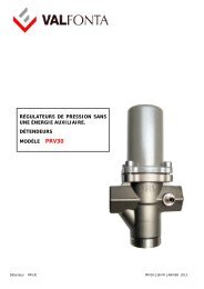
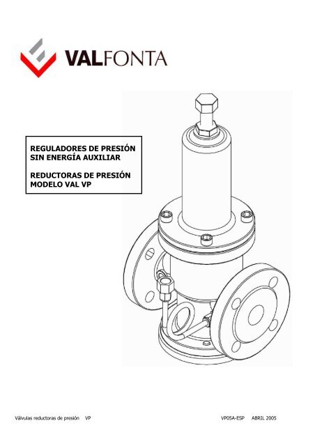
REGULADORES DE PRESIÓN<br />
SIN ENERGÍA AUXILIAR<br />
REDUCTORAS DE PRESIÓN<br />
MODELO VAL <strong>VP</strong><br />
<strong>Válvulas</strong> <strong>reductoras</strong> <strong>de</strong> <strong>presión</strong> <strong>VP</strong> <strong>VP</strong>05A-ESP ABRIL 2005
<strong>VALFONTA</strong><br />
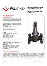
CARACTERÍSTICAS PRINCIPALES<br />
Válvula reductora <strong>de</strong> <strong>presión</strong> <strong>de</strong> acción directa<br />
autoaccionada por pistón. Controla la <strong>presión</strong> <strong>de</strong> salida<br />
aún habiendo oscilaciones en la <strong>presión</strong> <strong>de</strong> entrada.<br />
El pistón está guiado por 3 puntos.<br />
El mantenimiento <strong>de</strong> la reductora es muy escaso y se<br />
pue<strong>de</strong> acce<strong>de</strong>r a ella sin <strong>de</strong>smontarla <strong>de</strong> la línea <strong>de</strong><br />
consumo.<br />
Pintura EPOXY al horno <strong>de</strong> gran dureza.<br />
Rango <strong>de</strong> <strong>presión</strong> 1 a 20 bar r con el mismo muelle.<br />
Presión máxima admisible 40 bar.<br />
Temperatura máxima admisible 80 ºC.<br />
Fluidos<br />
Líquidos, aire comprimido, gases neutros.<br />
Material cuerpo PN25 → Nodular GGG40.3<br />
Bronce RG-10<br />
PN40 → Acero Carbono GSC25N<br />
Acero Inoxidable Aisi 316<br />
Material Interiores<br />
Bronce RG-10<br />
Acero Inoxidable AISI 304<br />
(Opción AISI 316)<br />
Aplicaciones<br />
Instalaciones laboratorios químicos, re<strong>de</strong>s <strong>de</strong> distribución<br />
<strong>de</strong> aguas, Instalaciones sanitarias, industriales, <strong>de</strong> aire<br />
comprimido, fuel-oil, contraincendios,...<br />
Observaciones<br />
La <strong>presión</strong> <strong>de</strong> salida tien<strong>de</strong> a igualarse a la <strong>presión</strong> <strong>de</strong><br />
entrada si se cierra el consumo y recupera la <strong>presión</strong> <strong>de</strong><br />
tarado cuando se reanuda el trabajo.<br />
Descripción<br />
Material<br />
1 Cuerpo GGG40.3 / RG-10 / GS-C-25N / Aisi 316<br />
2 Capuchón GGG40.3 / RG-10 / GS-C-25N / Aisi 316<br />
3 Tapa inferior RG-10 / GS-C-25N / Aisi 304<br />
3a Junta tórica tapa NBR 70-90 Shore A<br />
4 Buje central RG-10 / RG-10 / Aisi 304 / Aisi 304<br />
5 Émbolo menor Nitrilo 75º Shore A<br />
6 Émbolo mayor Nitrilo 75º Shore A<br />
7 Casquillo RG-10 / RG-10 / Aisi 304 / Aisi 304<br />
compensación<br />
7a Tórica NBR<br />
8a Casquillo central RG-10 / RG-10 / Aisi 304 / Aisi 304<br />
8a Junta plana Teflón<br />
9 Casquillo cierre RG-10 / RG-10 / Aisi 304 / Aisi 304<br />
9a Junta plana Teflón<br />
10 Soporte RG-10 / RG-10 / Aisi 304 / Aisi 304<br />
alojamiento cierre<br />
11 Aran<strong>de</strong>la cierre Neopreno<br />
12 Tornillo cierre Aisi 316<br />
13 Platillo resorte ST-52<br />
14 Tornillo regulación AM-52<br />
15 Tuerca regulación AM-52<br />
16 Racord Latón<br />
17 Muelle Acero Muelles<br />
18 Tornillos allen A-2<br />
19 Tornillos allen A-2<br />
20 Lira Tubo cobre 6x4<br />
21 Tornillo sujeción<br />
A-2<br />
buje<br />
22 Guía muelle ST-52<br />
23 Muelle cierre Acero Muelles<br />
TABLA DE MEDIDAS y Kv<br />
DN 20 25 32 40 50 65 80 100 125 150<br />
Valor Kv 9 9 13,5 22 32 57 82 115 190 240<br />
Bridas PN 16-25 - 160 180 200 230 290 310 350 400 450<br />
A<br />
Peso kgs 15 15 15 22 25 32 45 50 70 80<br />
Rosca BSP / NPT 140 140 145 180 190 255 - - - -<br />
A<br />
Peso Kgs 14 14 18 21 24 30 - - - -<br />
H 300 300 300 400 400 425 450 600 750 750<br />
Medidas en milímetros<br />
<strong>Válvulas</strong> <strong>reductoras</strong> <strong>de</strong> <strong>presión</strong> <strong>VP</strong> <strong>VP</strong>05A-ESP ABRIL 2005
<strong>VALFONTA</strong><br />
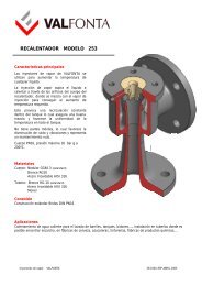
PRINCIPIO DE<br />
FUNCIONAMIENTO<br />
Las válvulas <strong>reductoras</strong> <strong>de</strong> <strong>presión</strong><br />
“<strong>VALFONTA</strong> <strong>VP</strong>” trabajan<br />
mediante el principio <strong>de</strong> acción<br />
directa. La <strong>presión</strong> aguas arriba<br />
llega a la válvula y empuja el<br />
pistón (4) hacia arriba ejerciendo<br />
el cierre <strong>de</strong> la misma<br />
automáticamente. Una vez cerrada<br />
la reductora hay que girar en<br />
sentido horario el tornillo <strong>de</strong><br />
regulación (14). Esto produce el<br />
<strong>de</strong>splazamiento <strong>de</strong>l muelle (17),<br />
que así mismo actúa sobre el buje<br />
(4) y el cierre (10 y 11) abriendo el<br />
paso <strong>de</strong> la válvula hasta que<br />
alcanza la <strong>presión</strong> aguas abajo<br />
solicitada. Cualquier variación<br />
sobre la <strong>presión</strong> aguas arriba será<br />
absorbida por la reductora<br />
mediante la compensación <strong>de</strong> las<br />
dos secciones <strong>de</strong>l buje (4),<br />
comunicadas por el agujero <strong>de</strong><br />
compensación.<br />
PROCEDIMIENTO PARA LA LIMPIEZA DE LA REDUCTORA<br />
DE PRESIÓN “VAL <strong>VP</strong>”<br />
1.- Cerrar todas las válvulas para que no llegue ningún fluido a la reductora<br />
2.- Si la válvula está instalada <strong>de</strong>ntro <strong>de</strong> un by-pass, cerrar las válvulas <strong>de</strong><br />
interrupción<br />
3.- Desmontar la lira (no es imprescindible)<br />
4.- Aflojar la tuerca (15) y el tornillo <strong>de</strong> regulación (14). Desmontar los tornillos<br />
allen (18) y sacar el capuchón(2) y el muelle (17).<br />
5.- Aflojar los tornillos allen (19) y <strong>de</strong>smontar la tapa inferior (3). Desmontar la<br />
tórica (3a) y sacar el muelle cierre (23)<br />
6.- Aflojar tornillo cierre (12) y extraer el soporte alojamiento cierre (10) con su<br />
aran<strong>de</strong>la cierre (11). Ahora po<strong>de</strong>mos extraer (hacia arriba) el buje central (4).<br />
7.- Ahora la válvula está vacía <strong>de</strong> elementos móviles y po<strong>de</strong>mos proce<strong>de</strong>r a su<br />
limpieza. Los casquillos nº 7-8-9 no se pue<strong>de</strong>n <strong>de</strong>smontar.<br />
Es muy importante limpiar con <strong>de</strong>tenimiento el agujero <strong>de</strong> compensación con<br />
un varilla pequeña.<br />
<strong>Válvulas</strong> <strong>reductoras</strong> <strong>de</strong> <strong>presión</strong> <strong>VP</strong> <strong>VP</strong>05A-ESP ABRIL 2005
<strong>VALFONTA</strong><br />
INSTALACIÓN<br />
Se recomienda la instalación según el esquema siguiente:<br />
1.- Válvula <strong>de</strong> interrupción<br />
2.- Filtro<br />
3.- Manómetro indicador <strong>presión</strong> <strong>de</strong> entrada<br />
4.- Manómetro indicador <strong>presión</strong> <strong>de</strong> salida<br />
5.- Válvula reductora <strong>de</strong> <strong>presión</strong> “<strong>VALFONTA</strong>”<br />
6.- Válvula <strong>de</strong> seguridad<br />
Distribuido por:<br />
<strong>Válvulas</strong> <strong>reductoras</strong> <strong>de</strong> <strong>presión</strong> <strong>VP</strong> <strong>VP</strong>05A-ESP ABRIL 2005