CB22Cover unisex.qxp - Chamberlain
CB22Cover unisex.qxp - Chamberlain
CB22Cover unisex.qxp - Chamberlain

Create successful ePaper yourself
Turn your PDF publications into a flip-book with our unique Google optimized e-Paper software.
ATTENTION<br />
IMPORTANT FITTING AND OPERATING INSTRUCTIONS<br />
en-1<br />
PLEASE START BY READING THESE IMPORTANT SAFETY RULES • SAVE THESE INSTRUCTIONS<br />
This safety alert symbol means "Caution" - failure to comply with such an instruction involves risk of personal injury or damage<br />
to property. Please read these warnings carefully.<br />
This gate drive mechanism is designed and tested to offer appropriately safe service provided it is installed and operated in<br />
strict accordance with the following safety rules.<br />
Incorrect installation and/or failure to comply with the following instructions may result in serious personal injury or property<br />
damage.<br />
When using tools and small parts to install or carry<br />
out repair work on a gate exercise caution and do not<br />
wear rings, watches or loose clothing.<br />
Installation and wiring must be in compliance with<br />
your local building and electrical installation codes.<br />
Power cables must only be connected to a properly<br />
earthed supply.<br />
Any entrapment possibility by the moving wing between<br />
wing & walls must be secured with safety edges or IRsensors.<br />
.<br />
Please remove any locks fitted to the gate in order to<br />
prevent damage to the gate.<br />
After the installation a final test of the full function of<br />
the system and the full function of the safety devices<br />
must be done.<br />
This drive cannot be used with a gate incorporating a<br />
wicket door unless the drive cannot be operated with<br />
the wicket door open.<br />
It is important to make sure that the gate always runs<br />
smoothly. Gates which stick or jam must be repaired<br />
immediately. Employ a qualified technician to repair the<br />
gate, never attempt to repair it yourself.<br />
Keep additional accessories away from children. Do not<br />
allow children to play with pushbuttons or remote controls.<br />
A gate can cause serious injuries as it closes.<br />
Disconnect electric power to the system before making<br />
repairs or removing covers.<br />
A disconnecting device must be provided in the<br />
permanently-wired installation to guarantee all-pole<br />
disconnection by means of a switch (at least 3mm<br />
contact gap) or by a separate fuse.<br />
Make sure that people who install, maintain or<br />
operate the gate drive follow these instructions. Keep<br />
these instructions in a safe place so that you can refer to<br />
them quickly when you need to.<br />
The full protection against potential squeeze or<br />
entrappment must work direct when the drive arms<br />
are installed.<br />
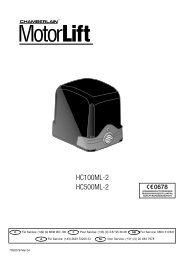
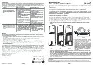
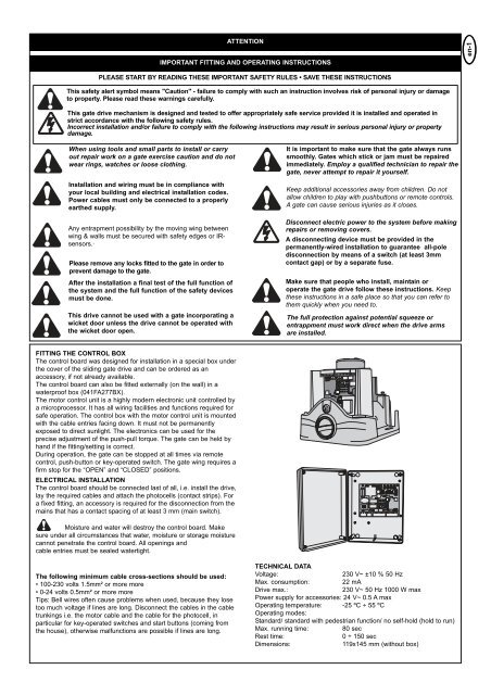
FITTING THE CONTROL BOX<br />
The control board was designed for installation in a special box under<br />
the cover of the sliding gate drive and can be ordered as an<br />
accessory, if not already available.<br />
The control board can also be fitted externally (on the wall) in a<br />
waterproof box (041FA277BX).<br />
The motor control unit is a highly modern electronic unit controlled by<br />
a microprocessor. It has all wiring facilities and functions required for<br />
safe operation. The control box with the motor control unit is mounted<br />
with the cable entries facing down. It must not be permanently<br />
exposed to direct sunlight. The electronics can be used for the<br />
precise adjustment of the push-pull torque. The gate can be held by<br />
hand if the fitting/setting is correct.<br />
During operation, the gate can be stopped at all times via remote<br />
control, push-button or key-operated switch. The gate wing requires a<br />
firm stop for the “OPEN” and “CLOSED” positions.<br />
ELECTRICAL INSTALLATION<br />
The control board should be connected last of all, i.e. install the drive,<br />
lay the required cables and attach the photocells (contact strips). For<br />
a fixed fitting, an accessory is required for the disconnection from the<br />
mains that has a contact spacing of at least 3 mm (main switch).<br />
Moisture and water will destroy the control board. Make<br />
sure under all circumstances that water, moisture or storage moisture<br />
cannot penetrate the control board. All openings and<br />
cable entries must be sealed watertight.<br />
The following minimum cable cross-sections should be used:<br />
• 100-230 volts 1.5mm² or more more<br />
• 0-24 volts 0.5mm² or more more<br />
Tips: Bell wires often cause problems when used, because they lose<br />
too much voltage if lines are long. Disconnect the cables in the cable<br />
trunkings i.e. the motor cable and the cable for the photocell, in<br />
particular for key-operated switches and start buttons (coming from<br />
the house), otherwise malfunctions are possible if lines are long.<br />
TECHNICAL DATA<br />
Voltage:<br />
230 V~ ±10 % 50 Hz<br />
Max. consumption:<br />
22 mA<br />
Drive max.:<br />
230 V~ 50 Hz 1000 W max<br />
Power supply for accessories: 24 V~ 0.5 A max<br />
Operating temperature: -25 ºC ÷ 55 ºC<br />
Operating modes:<br />
Standard/ standard with pedestrian function/ no self-hold (hold to run)<br />
Max. running time:<br />
80 sec<br />
Rest time:<br />
0 ÷ 150 sec<br />
Dimensions:<br />
119x145 mm (without box)