Automatismo para puerta corredera LineaMatic - Hörmann
Automatismo para puerta corredera LineaMatic - Hörmann
Automatismo para puerta corredera LineaMatic - Hörmann

Create successful ePaper yourself
Turn your PDF publications into a flip-book with our unique Google optimized e-Paper software.
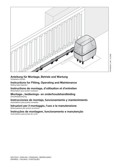
TR10A059-C RE / 10.2008<br />
Anleitung für Montage, Betrieb und Wartung<br />
Schiebetor-Antrieb<br />
Instructions for Fitting, Operating and Maintenance<br />
Sliding Gate Operator<br />
Instructions de montage, d’utilisation et d’entretien<br />
Motorisation pour portail coulissant<br />
Montage-, bedienings- en onderhoudshandleiding<br />
Schuifhekaandrijving<br />
Instrucciones de montaje, funcionamiento y mantenimiento<br />
<strong>Automatismo</strong> <strong>para</strong> <strong>puerta</strong> <strong>corredera</strong><br />
Istruzioni per il montaggio, l‘uso e la manutenzione<br />
Motorizzazione per portoni scorrevoli<br />
Instruções de montagem, funcionamento e manutenção<br />
<strong>Automatismo</strong> <strong>para</strong> portas de correr<br />
Deutsch / English / Français / Nederlands /<br />
Español / Italiano / Português
DEUTSCH ........................ 5<br />
ENGLISH ........................ 20<br />
FRANÇAIS ....................... 35<br />
NEDERLANDS. ................... 51<br />
ESPAÑOL. ....................... 67<br />
ITALIANO. ....................... 83<br />
PORTUGUÊS. .................... 99<br />
..................... 115<br />
2 TR10A059-C RE / 10.2008
A<br />
B<br />
17 mm<br />
2<br />
3 mm<br />
Ø 5,5 mm<br />
Ø 12 mm<br />
TR10A059-C RE / 10.2008 3
C 1<br />
6 x 6 x<br />
438 634<br />
C 2<br />
438 632<br />
2/2.2a<br />
40<br />
1020<br />
28<br />
6.5<br />
17.5<br />
C 3<br />
438 631<br />
28<br />
36<br />
6.5<br />
17.5 7.5<br />
C 4<br />
438 759 2/2.2b<br />
C<br />
438 765<br />
5<br />
8.2<br />
9<br />
8<br />
28.5<br />
8 10.5<br />
37<br />
25<br />
30<br />
7.5<br />
240<br />
100<br />
100<br />
240<br />
920<br />
2/2.2a<br />
240<br />
920<br />
100 100<br />
240<br />
1020<br />
6 8.7<br />
52<br />
1004<br />
450 450<br />
4 TR10A059-C RE / 10.2008
DEUTSCH<br />
Inhaltsverzeichnis<br />
A Mitgelieferte Artikel................................................. 3<br />
B Benötigtes Werkzeug zur Montage<br />
des Schiebetor-Antriebes....................................... 3<br />
C 1 Montagezubehör für<br />
die Kunststoff-Zahnstangen................................... 4<br />
C 2 Zahnstange aus Kunststoff mit Stahlkern<br />
(Montagelasche unten)........................................... 4<br />
C 3 Zahnstange aus Kunststoff mit Stahlkern<br />
(Montagelasche oben)............................................ 4<br />
C 4 Zahnstange aus Stahl, verzinkt.............................. 4<br />
C 5 Montagezubehör für die Stahl-Zahnstangen........ 4<br />
Bohrschablone..................................................... 131<br />
1 Zu dieser Anleitung................................................. 6<br />
1.1 Bestimmungsgemäße Verwendung.......................... 6<br />
1.2 Mitgeltende Unterlagen............................................. 6<br />
1.3 Verwendete Warnhinweise........................................ 6<br />
2 Grundlegende Sicherheitshinweise....................... 6<br />
2.1 Qualifikation des Aufstellers...................................... 6<br />
2.2 Allgemeine Sicherheitshinweise................................ 6<br />
2.3 Sicherheitshinweise zur Montage.............................. 7<br />
2.4 Sicherheitshinweise zum Betrieb.............................. 7<br />
2.5 Sicherheitshinweise zur Wartung.............................. 7<br />
2.6 Hinweise zum Bildteil................................................ 7<br />
3 Definitionen.............................................................. 7<br />
4 Montage................................................................... 8<br />
4.1 Vorbereitung der Montage......................................... 8<br />
4.2 Montage des Schiebetor-Antriebes........................... 9<br />
4.2.1 Fundament für den Schiebetor-Antrieb..................... 9<br />
4.2.2 Ermitteln der Anbaumaße.......................................... 9<br />
4.2.3 Verankerung des Antriebes....................................... 9<br />
4.2.4 Öffnen des Antriebsgehäuses................................... 9<br />
4.2.5 Montage des Antriebsgehäuses................................ 9<br />
4.3 Montage der Zahnstange.......................................... 9<br />
4.4 Anschluss der Netzzuleitung................................... 10<br />
4.5 Montage des Platinenhalters................................... 10<br />
4.6 Montage des Magnethalters................................... 10<br />
4.7 Verriegeln des Antriebes.......................................... 10<br />
4.8 Elektrischer Anschluss............................................ 10<br />
4.9 Anschluss von Standardkomponenten................... 10<br />
4.10 Anschluss von Zusatzkomponenten/Zubehör......... 10<br />
4.10.1 Anschluss eines externen Funk-Empfängers*......... 10<br />
4.10.2 Anschluss externer Taster*...................................... 10<br />
4.10.3 Anschluss eines Ausschalters zum Anhalten des<br />
Antriebes (Halt- bzw. Not-Aus-Kreis)...................... 11<br />
4.10.4 Anschluss einer Warnleuchte*................................. 11<br />
4.10.5 Anschluss von Sicherheits-/Schutzeinrichtungen... 11<br />
4.10.6 Anschluss BUS........................................................ 11<br />
5 Inbetriebnahme...................................................... 11<br />
5.1 Allgemeines............................................................. 11<br />
5.2 Übersicht Einrichtbetrieb......................................... 11<br />
5.3 Vorbereitung............................................................ 11<br />
5.4 Einlernen der Torendlagen....................................... 11<br />
5.4.1 Endlagenerfassung Tor-Zu durch Endschalter........ 12<br />
5.4.2 Endlagenerfassung Tor-Auf..................................... 12<br />
5.4.3 Endlagenerfassung Teilöffnung............................... 12<br />
5.4.4 Abschluss des Einrichtbetriebes............................. 12<br />
5.4.5 Referenzfahrt........................................................... 12<br />
5.5 Kräfte lernen............................................................ 12<br />
5.6 Startpunkte für Schleichfahrt beim Öffnen und<br />
Schließen ändern..................................................... 13<br />
5.7 Reversiergrenze....................................................... 13<br />
5.8 Übersicht und Einstellungen der DIL‐Schalter........ 13<br />
5.8.1 DIL-Schalter 1......................................................... 13<br />
5.8.2 DIL-Schalter 2......................................................... 13<br />
5.8.3 DIL-Schalter 3 / DIL-Schalter 4............................... 13<br />
5.8.4 DIL-Schalter 5 / DIL-Schalter 6............................... 14<br />
5.8.5 DIL-Schalter 7......................................................... 14<br />
5.8.6 DIL-Schalter 8 / DIL-Schalter 9............................... 14<br />
5.8.7 DIL-Schalter 10....................................................... 14<br />
5.8.8 DIL-Schalter 11....................................................... 14<br />
5.8.9 DIL-Schalter 12....................................................... 14<br />
6 Handsender............................................................ 14<br />
6.1 Bedienelemente....................................................... 14<br />
6.2 Wichtige Hinweise zum Gebrauch des<br />
Handsenders........................................................... 14<br />
6.3 Wiederherstellen des Werkscodes.......................... 15<br />
7 Funk-Fernsteuerung.............................................. 15<br />
7.1 Integrierter Funkempfänger..................................... 15<br />
7.2 Einprogrammieren der Handsendertasten an<br />
einem integrierten Funkempfänger......................... 15<br />
7.3 Löschen aller Daten eines integrierten<br />
Funkempfängers..................................................... 15<br />
7.3.1 Anschluss eines externen Funk-Empfängers*......... 15<br />
8 Den Schiebetor-Antrieb auf die<br />
Werkseinstellung zurücksetzen........................... 16<br />
9 Betrieb.................................................................... 16<br />
9.1 Verhalten bei einem Spannungsausfall................... 16<br />
9.2 Verhalten nach einem Spannungsausfall................ 16<br />
10 Prüfung und Wartung............................................ 16<br />
10.1 Betriebs-, Fehler- und Warnmeldungen.................. 16<br />
10.1.1 LED GN................................................................... 16<br />
10.1.2 LED RT.................................................................... 17<br />
10.2 Fehlerquittierung..................................................... 17<br />
11 Demontage und Entsorgung................................ 17<br />
12 Optionales Zubehör............................................... 17<br />
13 Garantiebedingungen............................................ 18<br />
14 Technische Daten.................................................. 18<br />
15 Übersicht DIL-Schalter Funktionen..................... 19<br />
Bildteil.................................................115-129<br />
Weitergabe sowie Vervielfältigung dieses Dokuments,<br />
Verwertung und Mitteilung seines Inhalts sind verboten,<br />
soweit nicht ausdrücklich gestattet. Zuwiderhandlungen<br />
verpflichten zu Schadenersatz. Alle Rechte für den Fall der<br />
Patent-, Gebrauchsmuster- oder<br />
Geschmacksmustereintragung vorbehalten. Änderungen<br />
vorbehalten.<br />
TR10A059-C RE / 10.2008 5
DEUTSCH<br />
1<br />
Zu dieser Anleitung<br />
Sehr geehrte Kundin, sehr geehrter Kunde,<br />
wir freuen uns, dass Sie sich für ein Qualitätsprodukt aus<br />
unserem Hause entschieden haben.<br />
Lesen Sie die Anleitung sorgfältig und vollständig durch: sie<br />
enthält wichtige Informationen zum Produkt. Beachten Sie die<br />
Hinweise und befolgen Sie insbesondere die Sicherheits- und<br />
Warnhinweise.<br />
Bewahren Sie die Anleitung sorgfältig auf und stellen Sie<br />
sicher, dass sie jederzeit verfügbar und vom Benutzer des<br />
Produkts einsehbar ist.<br />
1.1 Bestimmungsgemäße Verwendung<br />
Der Schiebetor-Antrieb ist ausschließlich für den Betrieb von<br />
leichtgängigen Schiebetoren im privaten, nichtgewerblichen<br />
Bereich vorgesehen. Die max. zulässige Torgröße und das<br />
max. Gewicht dürfen nicht überschritten werden.<br />
Beachten Sie bitte die Herstellerangaben bezüglich der<br />
Kombination von Tor und Antrieb. Mögliche Gefährdungen im<br />
Sinne der EN 12604, EN 12605, EN 12445 und EN 12453<br />
werden durch die Konstruktion und Montage nach unseren<br />
Vorgaben vermieden. Toranlagen, die sich im öffentlichen<br />
Bereich befinden und über nur eine Schutzeinrichtung, z.B.<br />
Kraftbegrenzung verfügen, dürfen ausschließlich unter<br />
Aufsicht betrieben werden.<br />
1.2 Mitgeltende Unterlagen<br />
Dem Endverbraucher müssen für die sichere Nutzung und<br />
Wartung der Toranlage folgende Unterlagen zur Verfügung<br />
gestellt werden:<br />
• diese Anleitung<br />
• beigefügtes Prüfbuch<br />
1.3<br />
Verwendete Warnhinweise<br />
ACHTUNG<br />
Kennzeichnet eine Gefahr, die zur Beschädigung oder<br />
Zerstörung des Produkts führen kann.<br />
Das allgemeine Warnsymbol kennzeichnet eine<br />
Gefahr, die zu Verletzungen oder zum Tod führen kann. Im<br />
Textteil wird das allgemeine Warnsymbol in Verbindung mit<br />
den nachfolgend beschriebenen Warnstufen verwendet. Im<br />
Bildteil verweist eine zusätzlich Angabe auf die<br />
Erläuterungen im Textteil.<br />
VORSICHT<br />
Kennzeichnet eine Gefahr, die zu leichten oder mittleren<br />
Verletzungen führen kann.<br />
WARNUNG<br />
Kennzeichnet eine Gefahr, die zum Tod oder zu schweren<br />
Verletzungen führen kann.<br />
GEFAHR<br />
Kennzeichnet eine Gefahr, die unmittelbar zum Tod oder zu<br />
schweren Verletzungen führt.<br />
2 Grundlegende Sicherheitshinweise<br />
Beachten Sie alle unsere Sicherheits- und Warnhinweise.<br />
Hinweis:<br />
Dem Endverbraucher müssen das Prüfbuch und die Anleitung<br />
für die sichere Nutzung und Wartung der Toranlage zur<br />
Verfügung gestellt werden.<br />
2.1 Qualifikation des Aufstellers<br />
Montage, Wartung, Re<strong>para</strong>tur und Demontage des<br />
Schiebetor-Antriebs sollten durch eine sachkundige Person<br />
ausgeführt werden. Eine sachkundige Person ist gemäß<br />
EN 12635 eine Person, die über eine geeignete Ausbildung,<br />
qualifiziertes Wissen und praktische Erfahrung verfügt, um<br />
eine Toranlage richtig und sicher zu montieren, zu prüfen und<br />
zu warten.<br />
ff Beauftragen Sie bei Versagen des Schiebetor-Antriebs<br />
unmittelbar einen Sachkundigen mit der Prüfung bzw. der<br />
Re<strong>para</strong>tur.<br />
2.2<br />
Allgemeine Sicherheitshinweise<br />
WARNUNG<br />
Verletzungsgefahr durch falsche Montage und<br />
Handhabung<br />
Eine falsche Montage oder Handhabung des Antriebes<br />
kann ungewollte Torbewegungen auslösen. Dadurch<br />
können Personen und Gegenstände eingeklemmt werden.<br />
ff Befolgen Sie alle Anweisungen, die in dieser Anleitung<br />
enthalten sind.<br />
Verletzungsgefahr bei Re<strong>para</strong>tur- und Einstellarbeiten<br />
Ein Fehler in der Toranlage oder ein falsch ausgerichtetes<br />
Tor können zu schweren Verletzungen führen<br />
ff Benutzen Sie die Toranlage nicht, wenn Re<strong>para</strong>turoder<br />
Einstellarbeiten durchgeführt werden müssen.<br />
• Wenn Sie diese Einbauanleitung und zusätzlich die<br />
folgenden Bedingungen beachten, kann davon<br />
ausgegangen werden, dass die Betriebskräfte nach<br />
DIN EN 12453 eingehalten werden:<br />
–– Der Schwerpunkt des Tores muss in der Mitte des<br />
Tores liegen (maximal zulässige Abweichung ± 20%).<br />
–– Der Torlauf ist leichtgängig und weist keinerlei<br />
Steigung/Gefälle (0%) auf.<br />
–– An der oder den Schließkanten ist das Hörmann<br />
Dämpfungsprofil DP1 (Artikel-Nr.: 436 288) oder DP3<br />
(Artikel-Nr.: 436 388) montiert.<br />
–– Der Antrieb ist auf langsame Geschwindigkeit<br />
programmiert (Startpunkte für Schleichfahrt beim<br />
Öffnen und Schließen ändern auf Seite 13).<br />
–– Die Reversiergrenze bei 50 mm Öffnungsweite wird<br />
auf der ganzen Länge der Hauptschließkante<br />
überprüft und eingehalten.<br />
–– Der Tragrollenabstand bei freitragenden Toren<br />
(maximale Breite 6200 mm, maximale Öffnungsweite<br />
4000 mm) beträgt maximal 2000 mm.<br />
• Bevor Sie den Antrieb installieren, lassen Sie zu Ihrer<br />
eigenen Sicherheit eventuell erforderliche<br />
Re<strong>para</strong>turarbeiten durch einen qualifizierten<br />
Kundendienst ausführen.<br />
6 TR10A059-C RE / 10.2008
DEUTSCH<br />
2.3 Sicherheitshinweise zur Montage<br />
warnung<br />
Falsches Anbringen von<br />
Steuerungsgeräten<br />
Bei falsch angebrachten Steuerungsgeräten<br />
(wie z.B. Tastern) können ungewollt<br />
Torbewegungen auslösen und dabei Personen<br />
oder Gegenstände eingeklemmt werden.<br />
ff Montieren Sie fest installierte<br />
Steuerungsgeräte (wie Taster etc.) in<br />
Sichtweite des Tores aber, entfernt von<br />
sich bewegenden Teilen.<br />
ff Bringen Sie Steuerungsgeräte in einer<br />
Höhe von mindestens 1,5 m an (außer<br />
der Reichweite von Kindern).<br />
Beachten Sie bei der Montage folgende Punkte:<br />
• Der Aufsteller muss darauf achten, dass die nationalen<br />
Vorschriften für den Betrieb von elektrischen Geräten<br />
eingehalten werden.<br />
• Stellen Sie vor der Antriebs-Montage sicher, dass das Tor<br />
auch von Hand leicht zu bedienen ist. Der Einsatz an<br />
Toren mit Steigung oder Gefälle ist nicht zulässig.<br />
• Setzen Sie vor der Montage die mechanischen<br />
Verriegelungen des Tores, die nicht für eine Betätigung<br />
mit einem Schiebetor-Antrieb benötigt werden, außer<br />
Betrieb. Hierzu zählen insbesondere die<br />
Verriegelungsmechanismen des Torschlosses.<br />
• Kontrollieren Sie die gesamte Toranlage (Gelenke, Lager<br />
des Tores und Befestigungsteile) auf Verschleiß und<br />
eventuelle Beschädigungen. Prüfen Sie, ob Rost,<br />
Korrosion oder Risse vorhanden sind.<br />
• Bei der Durchführung der Montagearbeiten müssen die<br />
geltenden Vorschriften zur Arbeitssicherheit befolgt<br />
werden.<br />
• Decken Sie bei Bohrarbeiten den Antrieb ab, weil<br />
Bohrstaub und Späne zu Funktionsstörungen führen<br />
können.<br />
• Nach Abschluss der Montage muss der Errichter der<br />
Anlage entsprechend des Geltungsbereiches die<br />
Konformität nach DIN EN 13241-1 erklären.<br />
2.5 Sicherheitshinweise zur Wartung<br />
• Der Schiebetor-Antrieb ist wartungsfrei. Zu Ihrer eigenen<br />
Sicherheit empfehlen wir jedoch, die Toranlage nach<br />
Herstellerangaben durch einen Sachkundigen<br />
überprüfen zu lassen.<br />
• Alle Sicherheits- und Schutzfunktionen müssen<br />
monatlich auf ihre Funktion geprüft werden. Falls<br />
erforderlich, müssen vorhandene Fehler bzw. Mängel<br />
sofort behoben werden.<br />
• Die Prüfung und Wartung darf nur von einer<br />
sachkundigen Person durchgeführt werden. Wenden Sie<br />
sich hierzu an Ihren Lieferanten. Eine optische Prüfung<br />
kann vom Betreiber durchgeführt werden.<br />
• Für notwendige Re<strong>para</strong>turen wenden Sie sich an Ihren<br />
Lieferanten. Für nicht sach- oder fachgerecht ausgeführte<br />
Re<strong>para</strong>turen übernehmen wir keine Gewährleistung.<br />
2.6 Hinweise zum Bildteil<br />
Im Bildteil wird die Antriebs-Montage an einem Schiebetor<br />
dargestellt, an dem sich der Antrieb innen rechts vom<br />
geschlossenen Tor befindet. Bei Montage- bzw.<br />
Programmierabweichungen zum Schiebetor, an dem sich der<br />
Antrieb innen links vom geschlossenen Tor befindet, wird<br />
dieses zusätzlich gezeigt.<br />
Einige Bilder beinhalten zusätzlich das untenstehende Symbol<br />
mit einem Textverweis. Unter diesen Textverweisen erhalten<br />
Sie im Textteil wichtige Informationen zur Montage und zum<br />
Betrieb des Schiebetor-Antriebes.<br />
Beispiel:<br />
2.2<br />
Siehe Textteil, Kapitel 2.2<br />
Außerdem wird im Bild- sowie im Textteil an den Stellen, an<br />
denen die DIL-Schalter zum Einstellen der Steuerung erklärt<br />
werden, das folgende Symbol dargestellt.<br />
3<br />
Dieses Symbol kennzeichnet die<br />
Werkseinstellung/en der DIL-Schalter.<br />
Definitionen<br />
2.4<br />
Sicherheitshinweise zum Betrieb<br />
warnung<br />
Verletzungsgefahr bei Torbewegung<br />
Beim Schließen des Tores können Personen<br />
oder Gegenstände eingeklemmt werden.<br />
ff Stellen Sie sicher, dass sich im<br />
Bewegungsbereich des Tores keine<br />
Personen oder Gegenstände befinden.<br />
ff Stellen Sie sicher, dass keine Kinder an<br />
der Toranlage spielen.<br />
Aufhaltezeit<br />
Wartezeit vor der Zufahrt des Tores aus der Endlage Tor-Auf<br />
bei automatischem Zulauf.<br />
Automatischer Zulauf<br />
Selbsttätiges Schließen des Tores nach Ablauf einer Zeit, aus<br />
der Endlage Tor-Auf.<br />
DIL-Schalter<br />
Auf der Steuerungsplatine befindliche Schalter zum Einstellen<br />
der Steuerung.<br />
Durchfahrtslichtschranke<br />
Nach Durchfahren des Tores und der Lichtschranke wird die<br />
Aufhaltezeit unterbrochen und auf einen voreingestellten Wert<br />
gesetzt.<br />
Impuls-Steuerung<br />
Steuerung, die durch eine Folge von Impulsen das Tor<br />
abwechselnd Auf-Stopp-Zu-Stopp fahren lässt.<br />
TR10A059-C RE / 10.2008 7
DEUTSCH<br />
Kraft-Lernfahrt<br />
Bei dieser Lernfahrt werden die Kräfte eingelernt, die für das<br />
Verfahren des Tores notwendig sind.<br />
Normalfahrt<br />
Verfahren des Tores mit den eingelernten Strecken und<br />
Kräften.<br />
Referenzfahrt<br />
Torfahrt in Richtung Endlage Tor-Zu, um die Grundstellung<br />
festzulegen.<br />
Reversierfahrt<br />
Verfahren des Tores in Gegenrichtung beim Ansprechen der<br />
Sicherheitseinrichtungen.<br />
Reversiergrenze<br />
Die Reversiergrenze trennt den Bereich zwischen<br />
Reversierfahrt und Stoppen des Tores bei Kraftabschaltung in<br />
Endlage Tor-Zu.<br />
Schleichfahrt<br />
Der Bereich in dem das Tor sehr langsam verfährt, um sanft<br />
gegen die Endlage zu fahren.<br />
Teilöffnung<br />
Der Verfahrweg, der für den Personendurchgang geöffnet<br />
wird.<br />
Totmann-Fahrt<br />
Torfahrt, die nur so lange durchgeführt wird, wie die<br />
entsprechenden Taster betätigt werden.<br />
Vollöffnung<br />
Der Verfahrweg, wenn das Tor vollständig geöffnet wird.<br />
Vorwarnzeit<br />
Die Zeit zwischen dem Fahrbefehl (Impuls) und dem Beginn<br />
der Torfahrt.<br />
Werksreset<br />
Zurücksetzen der eingelernten Werte in den<br />
Auslieferungszustand / die Werkseinstellung.<br />
Farbcode für Leitungen, Einzeladern und Bauteile<br />
Die Abkürzungen der Farben für Leitung- und<br />
Aderkennzeichnung sowie Bauteilen folgen dem<br />
internationalen Farbcode nach IEC 757:<br />
BK Schwarz PK Rosa<br />
BN Braun RD Rot<br />
BU Blau SR Silber<br />
GD Gold TQ Türkis<br />
GN Grün VT Violett<br />
GN/YE Grün/Gelb WH Weiß<br />
GY Grau YE Gelb<br />
OG<br />
Orange<br />
4<br />
4.1<br />
Montage<br />
Vorbereitung der Montage<br />
WARNUNG<br />
Verletzungsgefahr durch beschädigte Bauteile<br />
Die Toranlage darf nicht benutzt werden, wenn Re<strong>para</strong>turoder<br />
Einstellarbeiten durchgeführt werden müssen. Ein<br />
Fehler in der Toranlage oder ein falsch ausgerichtetes Tor<br />
kann zu schweren Verletzungen führen.<br />
ff Kontrollieren Sie die gesamte Toranlage (Gelenke,<br />
Lager des Tores und Befestigungsteile) auf Verschleiß<br />
und eventuelle Beschädigungen. Prüfen Sie, ob Rost,<br />
Korrosion oder Risse vorhanden sind.<br />
ff Betreiben Sie den Schiebetor-Antrieb nur, wenn Sie<br />
den Bewegungsbereich des Tores einsehen können.<br />
ff Vergewissern Sie sich vor der Ein- bzw. Ausfahrt, ob<br />
das Tor auch ganz geöffnet wurde. Toranlagen dürfen<br />
erst durchfahren bzw. durchgangen werden, wenn das<br />
Tor zum Stillstand gekommen ist.<br />
Bevor Sie den Antrieb installieren, lassen Sie zu Ihrer eigenen<br />
Sicherheit eventuell erforderliche Wartungs- und<br />
Re<strong>para</strong>turarbeiten an der Toranlage durch einen<br />
Sachkundigen ausführen.<br />
Nur die korrekte Montage und Wartung durch einen<br />
kompetenten/sachkundigen Betrieb oder eine kompetente/<br />
sachkundige Person in Übereinstimmung mit den Anleitungen<br />
kann die sichere und vorgesehene Funktionsweise einer<br />
Montage sicherstellen.<br />
Der Sachkundige muss darauf achten, dass bei der<br />
Durchführung der Montagearbeiten die geltenden Vorschriften<br />
zur Arbeitssicherheit sowie die Vorschriften für den Betrieb<br />
von elektrischen Geräten befolgt werden. Hierbei müssen<br />
auch die nationalen Richtlinien beachtet werden. Mögliche<br />
Gefährdungen werden durch die Konstruktion und Montage<br />
nach unseren Vorgaben vermieden.<br />
ff Alle Sicherheits- und Schutzfunktionen müssen<br />
monatlich geprüft werden. Falls erforderlich, müssen die<br />
Fehler bzw. Mängel sofort behoben werden.<br />
Vor der Montage und Bedienung der Toranlage:<br />
WARNUNG<br />
Quetsch- und Schergefahr an den Schließkanten<br />
Bei der Torfahrt können Finger oder Gliedmaßen zwischen<br />
Tor und Schließkante eingequetscht oder abgetrennt<br />
werden.<br />
ff Berühren Sie während einer Torfahrt nicht die Hauptund<br />
Nebenschließkanten.<br />
ff Weisen Sie alle Personen, welche die Toranlage<br />
benutzen, in die ordnungsgemäße und sichere Bedienung<br />
ein.<br />
ff Demonstrieren und testen Sie die mechanische<br />
Entriegelung sowie den Sicherheitsrücklauf. Halten Sie<br />
dazu das Tor während des Torlaufes mit beiden Händen<br />
an. Die Toranlage muss den Sicherheitsrücklauf einleiten.<br />
8 TR10A059-C RE / 10.2008
DEUTSCH<br />
ff Setzen Sie vor der Montage die mechanischen<br />
Verriegelungen des Tores, die nicht für eine Betätigung<br />
mit einem Schiebetor-Antrieb benötigt werden, außer<br />
Betrieb oder demontieren Sie sie ggf. komplett. Hierzu<br />
zählen insbesondere die Verriegelungsmechanismen des<br />
Torschlosses.<br />
ff Überprüfen Sie, ob sich das Tor mechanisch in einem<br />
fehlerfreien Zustand befindet, so dass es von Hand leicht<br />
zu bedienen ist und sich richtig öffnen und schließen<br />
lässt (EN 12604).<br />
Hinweis:<br />
Die mitgelieferten Montagematerialien müssen auf Ihre<br />
Eignung für die Verwendung und den vorgesehenen<br />
Montageort vom Monteur überprüft werden.<br />
4.2<br />
Montage des Schiebetor-Antriebes<br />
4.2.1 Fundament für den Schiebetor-Antrieb<br />
ff Für den Schiebetor-Antrieb ist es erforderlich, dass ein<br />
Fundament gegossen wird, so wie es im Bild 1a bzw. im<br />
Bild 1b gezeigt ist - die Markierung * steht hierbei für<br />
die frostfreie Tiefe (in Deutschland = 80 cm).<br />
Bei Verwendung einer Schließkantensicherung muss ein<br />
größeres Fundament gegossen werden (siehe<br />
Bild 1c/1d).<br />
ff Bei Toren mit innenliegenden Laufrollen ist ggf. ein<br />
Sockelfundament erforderlich. Die Netzzuleitung mit<br />
230/240 V ~ für den Schiebetor-Antrieb muss durch ein<br />
Leerrohr im Fundament erfolgen. Die Zuleitung für den<br />
Anschluss von Zubehör mit 24 V muss durch ein<br />
se<strong>para</strong>tes Leerrohr, getrennt von der Netzzuleitung,<br />
erfolgen (siehe Bild 1.1).<br />
Hinweis:<br />
Das Fundament muss vor den folgenden Montageschritten<br />
ausreichend ausgehärtet sein.<br />
4.2.2 Ermitteln der Anbaumaße<br />
1. Vor dem Bohren der vier Ø 12 mm Bohrungen muss<br />
deren Lage auf der Oberfläche des Fundaments<br />
gekennzeichnet werden. Verwenden Sie hierzu die<br />
mitgelieferte Bohrschablone dieser Anleitung (siehe<br />
Bild 1.2).<br />
2. Wählen Sie zunächst die verwendete Zahnstange aus<br />
unten stehender Tabelle aus und entnehmen Sie die<br />
minimalen und maximalen Anbaumaße (Maß A).<br />
4.2.3<br />
Zahnstange<br />
min.<br />
Maß A (mm)<br />
max.<br />
438 759 126 138<br />
438 631 125 129<br />
438 632 129 133<br />
Verankerung des Antriebes<br />
ff Nach dem Bohren muss die Tiefe der Bohrungen<br />
überprüft werden (80 mm tief), sodass die<br />
Stockschrauben so weit eingeschraubt werden können,<br />
wie im Bild 1.2 gezeigt.<br />
Zur Montage der Stockschrauben im Fundament ist der<br />
im Lieferumfang enthaltene Steckschlüssel zu<br />
verwenden.<br />
4.2.4<br />
Öffnen des Antriebsgehäuses<br />
ACHTUNG<br />
Beschädigung durch Feuchtigkeit<br />
Eindringende Feuchtigkeit kann die Steuerung<br />
beschädigen.<br />
ff Schützen Sie beim Öffnen des Antriebsgehäuses die<br />
Steuerung vor Feuchtigkeit.<br />
ff Um den Schiebetor-Antrieb montieren zu können, muss<br />
der Gehäusedeckel geöffnet werden (sieh Bild 1.3).<br />
4.2.5 Montage des Antriebsgehäuses<br />
1. Den Antrieb entriegeln (siehe Bild 1.4).<br />
Hinweis:<br />
Beim Entriegeln des Antriebes senken sich der Motor und das<br />
Zahnrad in das Gehäuse ab.<br />
2. Die vorhandenen Anschlussklemmen abziehen, die<br />
Fixierschrauben des Platinenhalters lösen und den<br />
Platinenhalter komplett abnehmen (siehe Bild 1.5).<br />
3. Die Leerrohr-Dichtungen aus dem Lieferumfang im<br />
Antriebsgehäuse einsetzen (siehe Bild 1.6).<br />
Gegebenenfalls die Dichtung entsprechend dem Leerrohr<br />
passend zuschneiden.<br />
4. Zur einfachen Montage der Schrauben und Muttern, die<br />
mitgelieferte Montagehilfe auf den Steckschlüssel<br />
stecken.<br />
5. Beim Aufsetzen des Antriebsgehäuses auf die<br />
Stockschrauben muss die Netzzuleitung und ggf. die<br />
24 V-Anschlussleitung durch die zuvor eingesetzten<br />
Leerrohr-Dichtungen in das Antriebsgehäuse eingezogen<br />
werden.<br />
6. Das Antriebsgehäuse festschrauben (siehe Bild 1.6 und<br />
Bild 1.7).<br />
Dabei auf eine waagerechte, stabile und sichere<br />
Befestigung des Antriebes achten.<br />
7. Das Antriebsgehäuse gegen Feuchtigkeit und Ungeziefer<br />
versiegeln (siehe Bild 1.8).<br />
4.3<br />
Montage der Zahnstange<br />
Vor der Montage:<br />
ff Vor der Montage der Zahnstangen ist es erforderlich, den<br />
Schiebetor-Antrieb zu entriegeln (siehe Bild 1.4).<br />
ff Vor der Montage der Zahnstangen überprüfen, ob die<br />
erforderliche Einschraubtiefe zur Verfügung steht.<br />
ff Für die Montage der Zahnstangen am Schiebetor die<br />
Verbindungselemente (Schrauben und Muttern, etc.) aus<br />
dem se<strong>para</strong>t zu bestellenden Montagezubehör<br />
verwenden (siehe Bild C1 bzw. Bild C5).<br />
Hinweis:<br />
• Abweichend vom Bildteil müssen bei anderen Torarten –<br />
auch hinsichtlich der Einschraublänge – die jeweils<br />
geeigneten Verbindungselemente benutzt werden (z.B.<br />
müssen bei Holztoren entsprechende Holzschrauben<br />
verwendet werden).<br />
• Abweichend vom Bildteil kann sich je nach Materialstärke<br />
oder Werkstofffestigkeit der notwendige<br />
Kernlochdurchmesser ändern. Der notwendige<br />
Durchmesser kann bei Alu Ø 5,0–5,5 mm und bei Stahl<br />
Ø 5,7–5,8 mm betragen.<br />
TR10A059-C RE / 10.2008 9
DEUTSCH<br />
Montage:<br />
ACHTUNG<br />
Beschädigung durch Schmutz<br />
Bei Bohrarbeiten können Bohrstaub und Späne zu<br />
Funktionsstörungen führen.<br />
ff Decken Sie bei Bohrarbeiten den Antrieb ab.<br />
1. Zur einfachen Montage der Zahnstangen, die<br />
mitgelieferten Kunststoff-Zahnräder in die Löcher der<br />
Zahnrad-Kappe stecken (siehe Bild 2.1).<br />
2. Legen Sie die Mitte die Zahnstange fest auf beide<br />
Kunststoff-Zahnräder auf.<br />
3. Zeichnen Sie die Position der Bohrungen am Tor an.<br />
ff Achten sie bei der Montage auf versatzfreie Übergänge<br />
zwischen den einzelnen Zahnstangen, damit ein<br />
gleichmäßiger Lauf des Tores gewährleistet wird.<br />
ff Nach der Montage müssen die Zahnstangen und das<br />
Zahnrad des Antriebs zueinander ausgerichtet werden.<br />
Dazu können sowohl die Zahnstangen als auch das<br />
Antriebsgehäuse justiert werden.<br />
Falsch montierte oder schlecht ausgerichtete<br />
Zahnstangen können zu unbeabsichtigtem<br />
Reversieren führen. Die vorgegebenen Maße müssen<br />
zwingend eingehalten werden!<br />
4.4 Anschluss der Netzzuleitung<br />
Der Netzanschluss erfolgt direkt an der Steckklemme am<br />
Transformator mittels Erdkabel NYY (siehe Bild 2.4). Dabei die<br />
Sicherheitshinweise aus Elektrischer Anschluss auf Seite 10<br />
beachten.<br />
4.5 Montage des Platinenhalters<br />
1. Den Platinenhalter mit den zwei zuvor gelösten<br />
Schrauben B , sowie zwei weiteren aus dem<br />
Lieferumfang, befestigen (siehe Bild 2.5).<br />
2. Die Anschlussklemmen wieder aufstecken.<br />
4.6 Montage des Magnethalters<br />
1. Das Tor per Hand in die Tor-Zu Position schieben.<br />
2. Den mitgelieferten Magnetschlitten in mittlerer Position<br />
komplett vormontieren (siehe Bild 2.6).<br />
3. Die Zahnstangenklammer so auf der Zahnstange<br />
montieren, dass bei geschlossenem Tor der Magnet um<br />
ca. 20 mm versetzt zugenau gegenüber dem Reed-<br />
Kontakt im Platinenhalter des Antriebsgehäuses<br />
positioniert ist.<br />
Hinweis:<br />
Wenn sich das Tor nicht leichtgängig in die gewünschte<br />
Endlage Tor-Zu schieben lässt, die Tormechanik für einen<br />
Betrieb mit dem Schiebetor-Antrieb überprüfen<br />
(Sicherheitshinweise zur Montage, Seite 7).<br />
4.7 Verriegeln des Antriebes<br />
ff Durch das Verriegeln wird der Antrieb wieder<br />
eingekuppelt. Während der Mechanismus in die<br />
Verriegelungsposition gedreht wird, muss der Motor<br />
leicht angehoben werden (siehe Bild 3).<br />
4.8 Elektrischer Anschluss<br />
gefahr<br />
Gefährliche elektrische Spannung<br />
Zum Betrieb dieses Gerätes ist Netzspannung erforderlich.<br />
Unsachgemäßer Umgang kann Stromschläge verursachen,<br />
die zum Tod oder zu schweren Verletzungen führen können.<br />
ff Elektroanschlüsse dürfen nur von einer Elektrofachkraft<br />
durchgeführt werden.<br />
ff Schalten Sie vor allen Arbeiten an der Toranlage den<br />
Antrieb spannungsfrei.<br />
ff Die bauseitige Elektroinstallation muss den jeweiligen<br />
Schutzbestimmungen entsprechen.<br />
ff Montieren sie alle Kabel von unten verzugsfrei in den<br />
Antrieb.<br />
ACHTUNG<br />
Zerstörung der Elektronik durch Fremdspannung<br />
Fremdspannung an den Anschlussklemmen der Steuerung<br />
führt zu einer Zerstörung der Elektronik.<br />
ff Verlegen Sie die Leitungen des Antriebes in einem<br />
getrennten Installationssystem zur Netzspannung.<br />
ff Verwenden Sie Erdkabel (NYY) für Leitungen, die im<br />
Erdreich verlegt werden (siehe Bild 1).<br />
4.9 Anschluss von Standardkomponenten<br />
Der Netzanschluss erfolgt direkt an der Steckklemme am<br />
Transformator mittels Erdkabel NYY (siehe Bild 2.4).<br />
4.10 Anschluss von Zusatzkomponenten/Zubehör<br />
Bei Anschluss von Zubehör an folgende Klemmen darf der<br />
entnommene Summenstrom max. 500 mA betragen:<br />
• 24 V=<br />
• SE3/LS<br />
• ext. Funk<br />
• SE1/SE2<br />
4.10.1 Anschluss eines externen Funk-Empfängers*<br />
ff<br />
Siehe Bild 4.1<br />
(*Zubehör, ist nicht in der Standard-Ausstattung enthalten!)<br />
ff Die Adern eines externen Funk-Empfängers wie folgt<br />
anschließen:<br />
–– GN an die Klemme 20 (0 V)<br />
–– WH an die Klemme 21 (Signal Kanal 1)<br />
–– BN an die Klemme 5 (+24 V)<br />
–– YE an die Klemme 23 (Signal für die Teilöffnung<br />
Kanal 2). Nur bei einem 2-Kanal-Empfänger.<br />
Hinweis:<br />
Die Antennenlitze vom externen Funk-Empfänger sollte nicht<br />
mit Gegenständen aus Metall (Nägel, Streben, usw.) in<br />
Verbindung kommen. Die beste Ausrichtung muss durch<br />
Versuche ermittelt werden. GSM-900-Handys können bei<br />
gleichzeitiger Benutzung die Reichweite der<br />
Funkfernsteuerung beeinflussen.<br />
4.10.2 Anschluss externer Taster*<br />
ff<br />
Siehe Bild 4.2<br />
(*Zubehör, ist nicht in der Standard-Ausstattung enthalten!)<br />
Ein oder mehrere Taster mit Schließerkontakten (potentialfrei),<br />
z.B. Schlüsseltaster, können <strong>para</strong>llel angeschlossen werden,<br />
max. Leitungslänge 10 m.<br />
10 TR10A059-C RE / 10.2008
DEUTSCH<br />
Impulssteuerung:<br />
ff<br />
Erster Kontakt an Klemme 21<br />
ff<br />
Zweiter Kontakt an Klemme 20<br />
Teilöffnung:<br />
ff<br />
Erster Kontakt an Klemme 23<br />
ff<br />
Zweiter Kontakt an Klemme 20<br />
Hinweis:<br />
Wird für einen externen Taster eine Hilfsspannung benötigt, so<br />
steht dafür an der Klemme 5 eine Spannung von +24 V DC<br />
(gegen die Klemme 20 = 0 V) bereit.<br />
4.10.3 Anschluss eines Ausschalters zum Anhalten<br />
des Antriebes (Halt- bzw. Not-Aus-Kreis)<br />
Ein Ausschalter mit Öffnerkontakten (nach 0 V schaltend oder<br />
potentialfrei) wird wie folgt angeschlossen (siehe Bild 4.3):<br />
1. Die werkseitig eingesetzte Drahtbrücke zwischen<br />
Klemme 12 und Klemme 13 entfernen.<br />
–– Klemme 12: Halt- bzw. Not-Aus-Eingang<br />
–– Klemme 13: 0 V, ermöglicht eine normale Funktion<br />
des Antriebes<br />
2. Schaltausgang oder ersten Kontakt an Klemme 12 (Haltbzw.<br />
Not-Aus-Eingang) anschließen.<br />
3. 0 V (Masse) oder zweiten Kontakt an Klemme 13 (0 V)<br />
anschließen.<br />
Hinweis:<br />
Durch das Öffnen des Kontaktes werden eventuelle Torfahrten<br />
sofort angehalten und dauerhaft unterbunden.<br />
4.10.4 Anschluss einer Warnleuchte*<br />
ff<br />
Siehe Bild 4.4<br />
(*Zubehör, ist nicht in der Standard-Ausstattung enthalten!)<br />
An den potentialfreien Kontakten am Stecker Option kann<br />
eine Warnleuchte oder die Endlagenmeldung Tor-Zu<br />
angeschlossen werden.<br />
Für den Betrieb (z.B. Warnmeldungen vor und während der<br />
Torfahrt) mit einer 24 V Lampe (max. 7 W) kann die Spannung<br />
am Stecker 24 V = herangezogen werden.<br />
Hinweis:<br />
Eine 230 V-Warnleuchte (siehe Endlagenerfassung Tor-Zu<br />
durch Endschalter, Seite 12) muss direkt versorgt werden.<br />
4.10.5 Anschluss von Sicherheits-/<br />
Schutzeinrichtungen<br />
ff<br />
Siehe Bild 4.5-4.7<br />
Es können Sicherheitseinrichtungen wie Lichtschranken/<br />
Schließkantensicherungen (SKS) oder<br />
8k2-Widerstandskontaktleisten angeschlossen werden:<br />
SE1<br />
SE2<br />
SE3<br />
in Richtung Öffnen, Sicherheitseinrichtung getestet<br />
oder Widerstandskontaktleiste 8k2.<br />
in Richtung Schließen, Sicherheitseinrichtung<br />
getestet oder Widerstandskontaktleiste 8k2.<br />
in Richtung Schließen, Lichtschranke ohne<br />
Testung oder dynamische 2-Draht-Lichtschranke,<br />
z.B. als Durchfahrtslichtschranke.<br />
Die Auswahl für die 3 Sicherheitskreise kann über DIL-<br />
Schalter eingestellt werden (siehe Übersicht und Einstellungen<br />
der DIL‐Schalter, Seite 13).<br />
Klemme 20<br />
Klemme 18<br />
Klemmen 71/72/73<br />
Klemme 5<br />
0 V (Spannungsversorgung)<br />
Testsignal<br />
Signal der Sicherheitseinrichtung<br />
+24 V (Spannungsversorgung)<br />
Hinweis:<br />
Sicherheitseinrichtungen ohne Testung (z.B. statische<br />
Lichtschranken) müssen halbjährlich geprüft werden. Sie sind<br />
nur für den Sachschutz zulässig!<br />
4.10.6 Anschluss BUS<br />
ff<br />
Siehe Bild 4.8<br />
5 Inbetriebnahme<br />
ff Vor der Erstinbetriebnahme alle Anschlussleitungen auf<br />
die korrekte Installation an allen Anschlussklemmen<br />
überprüfen.<br />
ff Das Tor halb öffnen.<br />
ff Den Antrieb einkuppeln.<br />
5.1 Allgemeines<br />
Die Steuerung wird mittels DIL-Schalter programmiert.<br />
Änderungen der DIL-Schaltereinstellungen sind nur unter<br />
folgenden Voraussetzungen zulässig:<br />
• Der Antrieb steht.<br />
• Es ist keine Vorwarn- oder Aufhaltezeit aktiv.<br />
5.2 Übersicht Einrichtbetrieb<br />
In folgenden Kapiteln wird der Einrichtbetrieb beschrieben:<br />
• Vorbereitung, Seite 11<br />
• Einlernen der Torendlagen, Seite 11<br />
––<br />
Endlagenerfassung Tor-Zu durch Endschalter,<br />
Seite 12<br />
––<br />
Endlagenerfassung Tor-Auf, Seite 12<br />
––<br />
Endlagenerfassung Teilöffnung, Seite 12<br />
• Kräfte lernen, Seite 12<br />
• Startpunkte für Schleichfahrt beim Öffnen und Schließen<br />
ändern, Seite 13<br />
• Reversiergrenze, Seite 13<br />
5.3 Vorbereitung<br />
ff Alle DIL-Schalter müssen sich in der Werkseinstellung<br />
befinden, d.h. alle Schalter stehen auf OFF (siehe Bild 5).<br />
Folgende DIL-Schalter umstellen:<br />
f f DIL-Schalter 1: Einbaurichtung (siehe Bild 5.1)<br />
ON Tor schließt nach rechts<br />
(vom Antrieb aus gesehen)<br />
Tor schließt nach links<br />
OFF (vom Antrieb aus gesehen)<br />
f f DIL-Schalter 3-7: Sicherheitseinrichtungen<br />
entsprechend einstellen (siehe Kapitel DIL-Schalter 3 /<br />
DIL-Schalter 4 bis DIL-Schalter 7 ab Seite 13).<br />
5.4 Einlernen der Torendlagen<br />
f f DIL-Schalter 2: Einrichtbetrieb (siehe Bild 6.1)<br />
ON Einlernen des Verfahrweges<br />
OFF<br />
TR10A059-C RE / 10.2008 11
DEUTSCH<br />
Hinweis:<br />
Im Einrichtbetrieb sind die Sicherheitseinrichtungen nicht<br />
aktiv.<br />
5.4.1 Endlagenerfassung Tor-Zu durch Endschalter<br />
Vor dem Einlernen der Endlagen muss der Endschalter (Reed-<br />
Kontakt) angeschlossen sein. Die Adern des Endschalters<br />
müssen an der Klemme REED angeklemmt sein (siehe<br />
Bild 6.1a). Das Optionsrelais hat beim Einrichten die gleiche<br />
Funktion wie die rote LED. Mit einer hier angeschlossenen<br />
Lampe lässt sich die Endschalterstellung aus der Ferne<br />
beobachten (siehe Bild 4.4).<br />
Einlernen der Endlage Tor-Zu:<br />
1. Das Tor etwas öffnen.<br />
2. Den Platinentaster T drücken und gedrückt halten.<br />
Das Tor fährt nun in Schleichfahrt in Richtung Tor-Zu. Bei<br />
Erreichen des Endschalters erlischt die rote LED.<br />
3. Den Platinentaster T unverzüglich loslassen.<br />
Das Tor befindet sich nun in der Endlage Tor-Zu.<br />
Hinweis:<br />
Fährt das Tor in Richtung Auf, befindet sich der<br />
DIL‐Schalter 1 in der falschen Position und muss umgestellt<br />
werden. Anschließend die Schritte 1 bis 3 wiederholen.<br />
Falls diese Position des geschlossenen Tores nicht der<br />
gewünschten Endlage Tor-Zu entspricht, muss nachjustiert<br />
werden.<br />
Endlage Tor-Zu nachjustieren:<br />
1. Die Position des Magneten durch Verschieben des<br />
Magnetschlittens verändern.<br />
2. Platinentaster T drücken, um der so verstellten Endlage<br />
zu folgen, bis die rote LED wieder erlischt.<br />
3. Diesen Vorgang so lange wiederholen, bis die<br />
gewünschte Endlage erreicht ist.<br />
5.4.2 Endlagenerfassung Tor-Auf<br />
ff<br />
Siehe Bild 6.1b<br />
Einlernen der Endlage Tor-Auf:<br />
1. Den Platinentaster T drücken und gedrückt halten.<br />
Das Tor fährt in Schleichfahrt auf.<br />
2. Ist die gewünschte Endlage Tor-Auf erreicht, den<br />
Platinentaster T loslassen.<br />
3. Platinentaster P drücken, um diese Position zu<br />
bestätigen.<br />
Die grüne LED signalisiert durch ein 2 Sekunden langes,<br />
sehr schnelles Blinken das Erfassen der Endlage Tor-Auf.<br />
5.4.3 Endlagenerfassung Teilöffnung<br />
Einlernen der Endlage Teilöffnung:<br />
1. Den Platinentaster T drücken und gedrückt halten, um<br />
das Tor in Richtung Tor-Zu zu fahren.<br />
2. Ist die gewünschte Endlage Teilöffnung erreicht, den<br />
Platinentaster T loslassen.<br />
3. Platinentaster P drücken um diese Position zu<br />
bestätigen.<br />
Die grüne LED signalisiert durch langsames Blinken das<br />
Erfassen der Endlage Teilöffnung.<br />
5.4.4 Abschluss des Einrichtbetriebes<br />
ff<br />
Nach Abschluss des Einlernvorgangs DIL‐Schalter 2<br />
(Funktion: Einlernen des Verfahrweges) auf OFF stellen.<br />
Die grüne LED signalisiert durch schnelles Blinken, dass<br />
Kraftlernfahrten durchgeführt werden müssen (siehe<br />
Bild 6.1c).<br />
Hinweis:<br />
Die Sicherheitseinrichtungen werden aktiv geschaltet.<br />
5.4.5 Referenzfahrt<br />
ff<br />
Siehe Bild 6.2<br />
Nach dem Einlernen der Endlagen ist die erste Fahrt immer<br />
eine Referenzfahrt. Während der Referenzfahrt wird das<br />
Optionsrelais getaktet und eine angeschlossene Warnleuchte<br />
blinkt.<br />
Referenzfahrt bis Endlage Tor-Zu:<br />
ff<br />
Den Platinentaster T einmal drücken.<br />
Der Antrieb fährt selbständig bis in die Endlage Tor-Zu.<br />
5.5 Kräfte lernen<br />
Nach dem Einlernen der Endlagen und der Referenzfahrt<br />
müssen die Kräfte in Kraftlernfahrten eingelernt werden.<br />
Hierfür sind drei ununterbrochene Tor-Zyklen erforderlich, bei<br />
denen keine Sicherheitseinrichtung ansprechen darf. Die<br />
Erfassung der Kräfte erfolgt in beide Richtungen automatisch<br />
im Selbsthaltebetrieb, d.h. der Antrieb verfährt nach einem<br />
Impuls selbständig bis in die Endlage. Während des gesamten<br />
Lernvorgangs blinkt die grüne LED. Nach Abschluss der<br />
Kraftlernfahrten leuchtet diese dann kontinuierlich.<br />
ff Die beiden folgenden Vorgänge müssen dreimal<br />
durchgeführt werden.<br />
Kraftlernfahrt bis Endlage Tor-Auf:<br />
ff<br />
Den Platinentaster T einmal drücken.<br />
Der Antrieb fährt selbständig bis in die Endlage Tor-Auf.<br />
Kraftlernfahrt bis Endlage Tor-Zu:<br />
ff<br />
Den Platinentaster T einmal drücken.<br />
Der Antrieb fährt selbständig bis in die Endlage Tor-Zu.<br />
Kraftbegrenzung einstellen:<br />
WARNUNG<br />
Verletzungsgefahr bei zu hoher Kraftbegrenzung<br />
Bei einer zu hoch eingestellten Kraftbegrenzung stoppt das<br />
Tor beim Schließen nicht rechtzeitig und kann dabei<br />
Personen oder Gegenstände einklemmen.<br />
ff Stellen Sie keine zu hohe Kraftbegrenzung ein.<br />
Hinweis:<br />
Aufgrund besonderer Einbausituationen kann es vorkommen,<br />
dass die zuvor gelernten Kräfte nicht ausreichen, was zu<br />
ungewollten Reversiervorgängen führen kann. In solchen<br />
Fällen kann die Kraftbegrenzung nachgestellt werden.<br />
1. Zum Einstellen der Kraftbegrenzung der Toranlage für die<br />
Auf- und Zufahrt steht ein Potentiometer zur Verfügung,<br />
welches auf der Steuerungsplatine im Antrieb mit Kraft F<br />
beschriftet ist.<br />
Die Erhöhung der Kraftbegrenzung erfolgt prozentual zu<br />
den gelernten Werten; dabei bedeutet die Stellung des<br />
Potentiometers die folgende Kraft-Zunahme (siehe<br />
Bild 7.1):<br />
12 TR10A059-C RE / 10.2008
DEUTSCH<br />
Linksanschlag<br />
Mittelstellung<br />
Rechtsanschlag<br />
+ 0 % Kraft<br />
+15 % Kraft<br />
+75 % Kraft<br />
2. Die eingelernte Kraft mittels einer geeigneten<br />
Kraftmesseinrichtung auf zulässige Werte im<br />
Geltungsbereich der EN 12453 und EN 12445 oder den<br />
entsprechenden nationalen Vorschriften prüfen.<br />
5.6 Startpunkte für Schleichfahrt beim Öffnen und<br />
Schließen ändern<br />
Die Länge der Schleichfahrt wird nach dem Einlernen der<br />
Endlagen automatisch auf einen Grundwert von ca. 500 mm<br />
vor den Endlagen gesetzt. Die Startpunkte können auf eine<br />
Länge von minimal ca. 300 mm bis zur gesamten Torlänge<br />
umprogrammiert werden (siehe Bild 7.2).<br />
Einrichten der Positionen – Schleichfahrt:<br />
1. Die Endlagen müssen eingerichtet sein und das Tor muss<br />
sich in Endlage Tor-Zu befinden.<br />
2. Der DIL-Schalter 2 muss auf OFF stehen.<br />
3. Zum Einrichten der Startpunkte für Schleichfahrt den<br />
DIL-Schalter 12 auf ON stellen.<br />
4. Platinentaster T drücken.<br />
Das Tor fährt in Normalfahrt mit Selbsthaltung in Richtung<br />
Tor-Auf.<br />
5. Passiert das Tor die gewünschte Position für den Beginn<br />
der Schleichfahrt, den Platinentaster P kurz drücken.<br />
Das Tor fährt die restliche Strecke zur Endlage Tor-Auf in<br />
Schleichfahrt.<br />
6. Platinentaster T nochmals drücken.<br />
Das Tor fährt wieder in Normalfahrt mit Selbsthaltung in<br />
Richtung Tor-Zu.<br />
7. Passiert das Tor die gewünschte Position für den Beginn<br />
der Schleichfahrt, den Platinentaster P kurz drücken.<br />
Das Tor fährt die restliche Strecke zur Endlage Tor-Zu in<br />
Schleichfahrt.<br />
8. Den DIL-Schalter 12 auf OFF stellen.<br />
Das Einstellen der Startpunkte für Schleichfahrt ist<br />
abgeschlossen.<br />
Hinweis:<br />
Die Startpunkte der Schleichfahrt können auch überlappend<br />
eingestellt werden; in diesem Fall wird die ganze<br />
Flügelbewegung in Schleichfahrt durchgeführt.<br />
Das Ändern der Startpunkte für Schleichfahrt hat zur Folge,<br />
dass die bereits eingelernten Kräfte gelöscht werden. Nach<br />
Abschluss der Änderung signalisiert das Blinken der grünen<br />
LED, dass erneut Kraftlernfahrten durchgeführt werden<br />
müssen.<br />
ff Die beiden folgenden Vorgänge müssen dreimal<br />
durchgeführt werden.<br />
Kraft-Lernfahrt bis Endlage Tor-Auf:<br />
ff<br />
Den Platinentaster T einmal drücken.<br />
Der Antrieb fährt selbständig bis in die Endlage Tor-Auf.<br />
Kraft-Lernfahrt bis Endlage Tor-Zu:<br />
ff<br />
Den Platinentaster T einmal drücken.<br />
Der Antrieb fährt selbständig bis in die Endlage Tor-Zu.<br />
verfährt in Gegenrichtung) läuft. Der Grenzbereich lässt sich<br />
wie folgt verändern (siehe Bild 7.3).<br />
Reversiergrenze einstellen:<br />
1. DIL-Schalter 11 auf ON stellen.<br />
Die Reversiergrenze kann nun stufig eingestellt werden.<br />
2. Platinentaster P kurz drücken, um die Reversiergrenze zu<br />
verringern.<br />
oder<br />
Platinentaster T kurz drücken, um die Reversiergrenze zu<br />
vergrößern.<br />
Beim Einstellen der Reversiergrenzen zeigt die grüne LED<br />
die folgenden Einstellungen an:<br />
1x blinken<br />
bis<br />
10x blinken<br />
minimale Reversiergrenze, die grüne<br />
LED blinkt einmal<br />
maximale Reversiergrenze, die grüne<br />
LED blinkt max. 10 mal<br />
3. DIL-Schalter 11 wieder auf OFF stellen, um die<br />
eingestellte Reversiergrenze zu speichern.<br />
5.8 Übersicht und Einstellungen der DIL‐Schalter<br />
Änderungen der DIL-Schalter-Einstellungen sind nur unter<br />
folgenden Voraussetzungen zulässig:<br />
• Der Antrieb steht.<br />
• Es ist keine Vorwarn- oder Aufhaltezeit aktiv.<br />
Entsprechend der nationalen Vorschriften, den gewünschten<br />
Sicherheitseinrichtungen und den örtlichen Gegebenheiten<br />
müssen die DIL-Schalter wie in den folgenden Abschnitten<br />
beschrieben eingestellt werden.<br />
5.8.1<br />
DIL-Schalter 1<br />
Einbaurichtung:<br />
ff<br />
Siehe Kapitel Vorbereitung, Seite 11<br />
5.8.2<br />
DIL-Schalter 2<br />
Einrichtbetrieb:<br />
ff<br />
Siehe Kapitel Einlernen der Torendlagen, Seite 11<br />
5.8.3 DIL-Schalter 3 / DIL-Schalter 4<br />
Sicherheitseinrichtung SE 1 (Öffnen):<br />
ff<br />
Siehe Bild 7.4<br />
Mit DIL-Schalter 3 in Kombination mit DIL-Schalter 4<br />
werden Art und Wirkung der Sicherheitseinrichtung<br />
eingestellt.<br />
3 ON Anschlusseinheit Schließkantensicherung oder<br />
Lichtschranke mit Testung<br />
3 OFF • Widerstandskontaktleiste 8k2<br />
• keine Sicherheitseinrichtung (Widerstand 8k2<br />
zwischen Klemme 20/72,<br />
Auslieferungszustand)<br />
4 ON verzögertes kurzes Reversieren in Richtung Tor-Zu<br />
(für Lichtschranke)<br />
4 OFF sofortiges kurzes Reversieren in Richtung Tor-Zu<br />
(für SKS)<br />
5.7 Reversiergrenze<br />
Beim Betrieb der Toranlage muss bei der Fahrt in Richtung<br />
Tor-Zu unterschieden werden, ob das Tor gegen den<br />
Endanschlag (Toranlage stoppt) oder gegen ein Hindernis (Tor<br />
TR10A059-C RE / 10.2008 13
DEUTSCH<br />
5.8.4<br />
DIL-Schalter 5 / DIL-Schalter 6<br />
ff<br />
Siehe Bild 7.7d<br />
Sicherheitseinrichtung SE 2 (Schließen):<br />
ff<br />
Siehe Bild 7.5<br />
Mit DIL-Schalter 5 in Kombination mit DIL-Schalter 6<br />
werden Art und Wirkung der Sicherheitseinrichtung<br />
eingestellt.<br />
5 ON Anschlusseinheit Schließkantensicherung oder<br />
Lichtschranke mit Testung<br />
5 OFF • Widerstandskontaktleiste 8k2<br />
• keine Sicherheitseinrichtung (Widerstand 8k2<br />
zwischen Klemme 20/73,<br />
Auslieferungszustand)<br />
6 ON verzögertes kurzes Reversieren in Richtung<br />
Tor-Auf (für Lichtschranke)<br />
6 OFF sofortiges kurzes Reversieren in Richtung Tor-Auf<br />
(für SKS)<br />
5.8.5 DIL-Schalter 7<br />
Schutzeinrichtung SE 3 (Schließen):<br />
ff<br />
Siehe Bild 7.6<br />
Verzögertes Reversieren bis in Endlage Tor-Auf.<br />
7 ON Dynamische 2-Draht-Lichtschranke<br />
7 OFF • ungetestete statische Lichtschranke<br />
• keine Sicherheitseinrichtung (Drahtbrücke<br />
zwischen Klemme 20/71,<br />
Auslieferungszustand)<br />
5.8.6 DIL-Schalter 8 / DIL-Schalter 9<br />
Mit DIL-Schalter 8 in Kombination mit DIL-Schalter 9<br />
werden die Funktionen des Antriebes (automatischer Zulauf /<br />
Vorwarnzeit) und die Funktion des Optionsrelais eingestellt.<br />
ff<br />
Siehe Bild 7.7a<br />
8 ON 9 ON Antrieb<br />
automatischer Zulauf, Vorwarnzeit bei<br />
jeder Torfahrt<br />
Optionsrelais<br />
Das Relais taktet bei der Vorwarnzeit<br />
schnell, während der Torfahrt normal und<br />
bei der Aufhaltezeit ist es aus.<br />
ff<br />
Siehe Bild 7.7b<br />
8 OFF 9 ON Antrieb<br />
automatischer Zulauf, Vorwarnzeit nur<br />
bei automatischem Zulauf<br />
Optionsrelais<br />
Das Relais taktet bei der Vorwarnzeit<br />
schnell, während der Torfahrt normal<br />
und bei der Aufhaltezeit ist es aus.<br />
ff<br />
Siehe Bild 7.7c<br />
8 ON 9 OFF Antrieb<br />
Vorwarnzeit bei jeder Torfahrt ohne<br />
automatischen Zulauf<br />
Optionsrelais<br />
Das Relais taktet bei der Vorwarnzeit<br />
schnell, während der Torfahrt normal.<br />
8 OFF 9 OFF Antrieb<br />
Ohne besondere Funktion<br />
Optionsrelais<br />
Das Relais zieht in der Endlage Tor-Zu<br />
an.<br />
Hinweis:<br />
Ein automatischer Zulauf ist immer nur aus den festgelegten<br />
Endlagen (Voll- oder Teilöffnung) möglich. Ist ein<br />
automatischer Zulauf dreimal fehlgeschlagen, wird er<br />
deaktiviert. Der Antrieb muss mit einem Impuls neu gestartet<br />
werden.<br />
5.8.7<br />
DIL-Schalter 10<br />
Wirkung der Schutzeinrichtung SE3 als<br />
Durchfahrtslichtschranke bei automatischem Zulauf<br />
ff<br />
Siehe Bild 7.8<br />
Mit diesem Schalter wird die Schutzeinrichtung SE3 als<br />
Durchfahrtslichtschranke bei automatischem Zulauf<br />
eingestellt.<br />
7 ON Die Lichtschranke ist als<br />
Durchfahrtslichtschranke aktiviert, nach<br />
Durchfahrt oder Durchgang der Lichtschranke<br />
wird die Aufhaltezeit verkürzt.<br />
7 OFF Die Lichtschranke ist nicht als<br />
Durchfahrtslichtschranke aktiviert. Ist aber<br />
automatischer Zulauf aktiviert und ist nach<br />
Ablauf der Aufhaltezeit die Lichtschranke<br />
unterbrochen, wird die Aufhaltezeit wieder auf<br />
die voreingestellte Zeit gesetzt.<br />
5.8.8<br />
DIL-Schalter 11<br />
Einrichten der Reversiergrenzen:<br />
ff<br />
Siehe Kapitel Reversiergrenze, Seite 13<br />
5.8.9<br />
DIL-Schalter 12<br />
Startpunkt der Schleichfahrt beim Öffnen und Schließen:<br />
ff<br />
Siehe Kapitel Startpunkte für Schleichfahrt beim Öffnen<br />
und Schließen ändern, Seite 13<br />
6<br />
Handsender<br />
6.1 Bedienelemente<br />
ff<br />
Siehe Bild 8<br />
1 LED<br />
2 Bedientasten<br />
3 Batteriefachdeckel<br />
4 Batterie<br />
5 Reset-Taster<br />
6 Handsenderhalterung<br />
6.2 Wichtige Hinweise zum Gebrauch des<br />
Handsenders<br />
• Verwenden Sie für die Inbetriebnahme der Fernsteuerung<br />
ausschließlich Originalteile.<br />
• Ist kein se<strong>para</strong>ter Zugang zur Garage vorhanden, so<br />
führen Sie jede Änderung oder Erweiterung von<br />
Programmierungen innerhalb der Garage durch.<br />
14 TR10A059-C RE / 10.2008
DEUTSCH<br />
• Führen Sie nach dem Programmieren oder Erweitern der<br />
Fernsteuerung eine Funktionsprüfung durch.<br />
• Handsender gehören nicht in Kinderhände und dürfen nur<br />
von Personen benutzt werden, die in die Funktionsweise<br />
der ferngesteuerten Toranlage eingewiesen sind.<br />
• Die Bedienung des Handsenders muss generell mit<br />
Sichtkontakt zum Tor erfolgen.<br />
• Toröffnungen von ferngesteuerten Toranlagen dürfen erst<br />
durchfahren bzw. durchgangen werden, wenn das<br />
Garagentor in der Endlage Tor-Auf steht.<br />
• Schützen Sie den Handsender vor folgenden<br />
Umwelteinflüssen:<br />
–– direkter Sonneneinstrahlung (zul.<br />
Umgebungstemperatur: –20 °C bis +60 °C)<br />
–– Feuchtigkeit<br />
–– Staubbelastung<br />
Bei Nichtbeachtung kann die Funktion beeinträchtigt<br />
werden!<br />
Vorsicht<br />
Unbeabsichtigte Torfahrt<br />
Während der Programmierung des Handsender kann es zu<br />
ungewollten Torfahrten kommen.<br />
ff Achten Sie darauf, dass sich bei der Programmierung<br />
und Erweiterung der Fernsteuerung keine Personen<br />
oder Gegenstände im Bewegungsbereich des Tores<br />
befinden.<br />
Hinweis:<br />
Die örtlichen Gegebenheiten können Einfluss auf die<br />
Reichweite der Fernsteuerung haben.<br />
6.3 Wiederherstellen des Werkscodes<br />
ff<br />
Siehe Bild 8<br />
Hinweis:<br />
Nachfolgende Bedienschritte sind nur bei versehentlichen<br />
Erweiterungs- oder Lernvorgängen erforderlich.<br />
Der Code-Platz jeder Taste des Handsenders kann wieder mit<br />
dem ursprünglichen Werkscode oder auch mit einem anderen<br />
Code belegt werden.<br />
1. Öffnen Sie den Batteriefachdeckel.<br />
Ein kleiner Taster ist auf der Platine zugänglich.<br />
Achtung<br />
Zerstörung des Tasters<br />
ff Verwenden Sie keine spitzen Gegenstände und drücken<br />
Sie nicht zu stark auf den Taster.<br />
2. Drücken Sie den Taster 5 mit einem stumpfen<br />
Gegenstand vorsichtig und halten Sie ihn gedrückt.<br />
3. Drücken Sie die Bedientaste, die codiert werden soll, und<br />
halten Sie diese gedrückt.<br />
Die LED des Senders blinkt langsam.<br />
4. Wenn Sie den kleinen Taster bis zum Ende des<br />
langsamen Blinkens gedrückt halten, wird die<br />
Bedientaste wieder mit dem ursprünglichen Werkscode<br />
belegt und die LED beginnt schneller zu blinken.<br />
5. Schließen Sie den Batteriefachdeckel.<br />
6. Führen Sie eine neue Programmierung des Empfängers<br />
durch.<br />
7 Funk-Fernsteuerung<br />
7.1 Integrierter Funkempfänger<br />
Der Schiebetor-Antrieb ist mit einem integrierten<br />
Funkempfänger ausgestattet. Bei dem integrierten<br />
Funkemfänger können die Funktionen Impuls (Auf-Stop-Zu-<br />
Stop) und Teilöffnung von je max. 12 verschiedenen<br />
Handsendertasten einprogrammiert werden. Werden mehr als<br />
je 12 Handsendertasten programmiert, wird die als Erstes<br />
programmierte ohne Vorwarnung gelöscht. Im<br />
Auslieferungszustand sind alle Speicherplätze leer.<br />
Funk programmieren / Daten löschen ist nur möglich, wenn<br />
folgendes gilt:<br />
• Es ist kein Einrichtbetrieb aktiviert ( DIL-Schalter 2 auf<br />
OFF).<br />
• Die Flügel werden nicht verfahren.<br />
• Zur Zeit ist keine Vorwarn- oder Aufhaltezeit aktiv.<br />
Hinweis:<br />
Zum Betrieb des Antriebes mit Funk muss eine<br />
Handsendertaste an einem integrierten Funkempfänger<br />
einprogrammiert sein. Der Abstand zwischen Handsender und<br />
Antrieb sollte mindestens 1 m betragen. GSM-900-Handys<br />
können bei gleichzeitiger Benutzung die Reichweite der<br />
Funkfernsteuerung beeinflussen.<br />
7.2 Einprogrammieren der Handsendertasten an<br />
einem integrierten Funkempfänger<br />
1. Den Platinentaster P einmal (für Kanal 1 = Impuls-Befehl)<br />
oder zweimal (für Kanal 2 = Teilöffnung-Befehl) kurz<br />
drücken.<br />
Ein weiteres Drücken des Platinentasters P beendet die<br />
Funk-Programmierbereitschaft sofort.<br />
Je nachdem welcher Kanal einprogrammiert werden soll,<br />
blinkt die rote LED nun 1x (für Kanal 1) oder 2x (für<br />
Kanal 2). In dieser Zeit kann eine Handsendertaste für die<br />
gewünschte Funktion einprogrammiert werden.<br />
2. Die Handsendertaste, die einprogrammiert werden soll,<br />
so lange drücken, bis die rote LED auf der Platine schnell<br />
blinkt.<br />
Der Funk-Code dieser Handsendertaste ist nun im<br />
integrierten Funkempfänger gespeichert (siehe Bild 9).<br />
7.3 Löschen aller Daten eines integrierten<br />
Funkempfängers<br />
ff<br />
Den Platinentaster P drücken und gedrückt halten.<br />
Die rote LED blinkt langsam und signalisiert die<br />
Löschbereitschaft. Das Blinken wechselt in einen<br />
schnelleren Rhythmus. Anschließend sind die<br />
einprogrammierten Funk-Codes aller Handsendertasten<br />
gelöscht.<br />
7.3.1 Anschluss eines externen Funk-Empfängers*<br />
(*Zubehör, ist nicht in der Standard-Ausstattung enthalten!)<br />
Anstatt des integrierten Funkempfängers kann zum Ansteuern<br />
des Schiebetor-Antriebes ein externer Funk-Empfänger für die<br />
Funktionen Impuls bzw. Teilöffnung verwendet werden. Der<br />
Stecker dieses Empfängers wird auf den entsprechenden<br />
Steckplatz gesteckt (siehe Bild 4.1). Um Doppelbelegungen<br />
zu vermeiden, sollte für den Betrieb mit einem externen Funk-<br />
Empfänger die Daten des integrierten Funkempfängers<br />
gelöscht werden (siehe Löschen aller Daten eines integrierten<br />
Funkempfängers, Seite 15).<br />
TR10A059-C RE / 10.2008 15
DEUTSCH<br />
8<br />
Den Schiebetor-Antrieb auf die<br />
Werkseinstellung zurücksetzen<br />
Steuerung (eingelernte Endlagen, Kräfte) zurückzusetzen:<br />
1. DIL-Schalter 2 auf ON stellen.<br />
2. Den Platinentaster P sofort kurz drücken.<br />
3. Wenn die rote LED schnell blinkt, den DIL-Schalter 2<br />
unverzüglich auf OFF stellen.<br />
Die Steuerung ist nun wieder auf die Werkseinstellung<br />
zurückgesetzt.<br />
9<br />
Betrieb<br />
WARNUNG<br />
Verletzungsgefahr beim Betrieb<br />
Beim Schließen des Tores können Personen oder<br />
Gegenstände eingeklemmt werden.<br />
ff Betreiben Sie den Schiebetor-Antrieb nur, wenn Sie<br />
den Bewegungsbereich des Tores einsehen können<br />
ff Vergewissern Sie sich vor der Ein- bzw. Ausfahrt, ob<br />
das Tor auch ganz geöffnet wurde. Toranlagen dürfen<br />
erst durchfahren bzw. durchgangen werden, wenn das<br />
Tor zum Stillstand gekommen ist.<br />
Quetsch- und Schergefahr<br />
Bei der Torfahrt können Finger oder Gliedmaßen von der<br />
Zahnstange sowie zwischen Tor und Schließkante<br />
eingequetscht oder abgetrennt werden.<br />
ff Greifen Sie während einer Torfahrt nicht mit den<br />
Fingern an die Zahnstange, das Zahnrad und die<br />
Haupt- und Nebenschließkanten.<br />
Vor dem Betrieb:<br />
ff Weisen Sie alle Personen, welche<br />
die Toranlage benutzen, in die<br />
ordnungsgemäße und sichere<br />
Bedienung ein.<br />
ff Demonstrieren und testen Sie die<br />
mechanische Entriegelung sowie<br />
den Sicherheitsrücklauf. Halten Sie<br />
dazu das Tor während des<br />
Torzulaufes mit beiden Händen an.<br />
Die Toranlage muss den<br />
Sicherheitsrücklauf einleiten.<br />
Die Steuerung befindet sich im normalen Fahrbetrieb:<br />
ff<br />
Platinentaster T, externen Taster drücken oder den<br />
Impuls 1 ansprechen.<br />
Das Tor verfährt im Impulsfolgebetrieb (Auf–Stopp–Zu–<br />
Stopp).<br />
Beim Ansprechen von Impuls 2 fährt das Tor in<br />
Teilöffnung (siehe Bild 4.1/4.2/9b).<br />
9.1 Verhalten bei einem Spannungsausfall<br />
Um das Schiebetor während eines Spannungsausfalls öffnen<br />
oder schließen zu können, muss es vom Antrieb entkuppelt<br />
werden.<br />
Achtung!<br />
Beschädigung durch Feuchtigkeit<br />
ff Schützen Sie beim Öffnen des Antriebsgehäuses die<br />
Steuerung vor Feuchtigkeit<br />
1. Gehäusedeckel entsprechend Bild 1.3 öffnen.<br />
2. Den Antrieb durch Drehen des<br />
Verriegelungsmechanismus entriegeln.<br />
Beim Entriegeln des Antriebes müssen ggf. der Motor<br />
und das Zahnrad von Hand heruntergedrückt werden,<br />
damit sie sich in das Gehäuse absenken (siehe Bild 11.1).<br />
Das Tor kann dann von Hand geöffnet und geschlossen<br />
werden.<br />
9.2 Verhalten nach einem Spannungsausfall<br />
Nach Spannungsrückkehr muss das Tor vor dem<br />
Endlagenschalter wieder an den Antrieb gekuppelt werden.<br />
ff Beim Drehen des Mechanismus in die<br />
Verriegelungsposition, den Motor leicht anheben (siehe<br />
Bild 11.2).<br />
Eine notwendige Referenzfahrt nach einem<br />
Spannungsausfall wird automatisch bei einem<br />
anstehenden Impuls-Befehl ausgeführt.<br />
Während dieser Referenzfahrt wird das Optionsrelais<br />
getaktet und eine angeschlossene Warnleuchte blinkt<br />
langsam.<br />
10 Prüfung und Wartung<br />
Der Schiebetor-Antrieb ist wartungsfrei. Die Toranlage muss<br />
nach Herstellerangaben durch einen Sachkundigen überprüft<br />
werden.<br />
Hinweis:<br />
• Die Prüfung und Wartung darf nur von einer<br />
sachkundigen Person durchgeführt werden. Wenden Sie<br />
sich hierzu an Ihren Lieferanten.<br />
• Eine optische Prüfung kann vom Betreiber durchgeführt<br />
werden. Betreffend notwendiger Re<strong>para</strong>turen wenden Sie<br />
sich an Ihren Lieferanten. Für nicht sach- oder<br />
fachgerecht ausgeführte Re<strong>para</strong>turen übernehmen wir<br />
keine Gewährleistung.<br />
• Widerstandskontaktleisten 8k2 halbjährlich auf ihre<br />
Funktion überprüfen.<br />
10.1<br />
Betriebs-, Fehler- und Warnmeldungen<br />
10.1.1 LED GN<br />
Die grüne LED (Bild 4) zeigt den Betriebszustand der<br />
Steuerung an:<br />
Dauerleuchten<br />
Normalzustand, alle Endlagen Tor-Auf und Kräfte sind<br />
eingelernt.<br />
schnelles Blinken<br />
Kraftlernfahrten müssen durchgeführt werden.<br />
langsames Blinken<br />
Einrichtbetrieb – Endlageneinstellung<br />
Beim Einrichten der Reversiergrenzen<br />
(siehe Reversiergrenze, Seite 13)<br />
• Blinkfrequenz ist proportional abhängig von der<br />
gewählten Reversiergrenze<br />
• Minimale Reversiergrenze: LED ist dauerhaft aus<br />
• Maximale Reversiergrenze: LED ist dauerhaft an<br />
16 TR10A059-C RE / 10.2008
DEUTSCH<br />
10.1.2 LED RT<br />
Die rote LED (Bild 4.1) zeigt an:<br />
im Einrichtbetrieb<br />
• Endschalter betätigt = LED Ein<br />
• Endschalter nicht betätigt = LED Aus<br />
Funk-Programmier-Anzeige<br />
Blinken wie in Einprogrammieren der Handsendertasten an<br />
einem integrierten Funkempfänger auf Seite 15<br />
beschrieben<br />
Anzeige der Betriebstaster-Eingänge, Funk<br />
• Betätigt = LED Ein<br />
• Nicht betätigt = LED Aus<br />
im Normal-Betrieb<br />
Blinkcode als Fehler-/Diagnoseanzeige<br />
Fehler-/Diagnoseanzeige<br />
Mit Hilfe der roten LED RT können Ursachen für den nicht<br />
erwartungsgemäßen Betrieb einfach identifiziert werden.<br />
Anzeige blinkt 2x<br />
Fehler/Warnung<br />
Sicherheits-/Schutzeinrichtung hat angesprochen<br />
mögliche Ursache<br />
• Sicherheits-/Schutzeinrichtung wurde betätigt<br />
• Sicherheits-/Schutzeinrichtung ist defekt<br />
• ohne SE1 fehlt der Widerstand 8k2 zwischen<br />
Klemme 20 und 72<br />
• ohne SE2 fehlt der Widerstand 8k2 zwischen<br />
Klemme 20 und 73<br />
• ohne SE3 fehlt die Drahtbrücke zwischen Klemme 20<br />
und 71<br />
Behebung<br />
• Sicherheits-/Schutzeinrichtung prüfen<br />
• überprüfen, ob ohne angeschlossene Sicherheits- /<br />
Schutzeinrichtung die entsprechenden Widerstände/<br />
Drahtbrücken vorhanden sind<br />
Anzeige blinkt 3x<br />
Fehler/Warnung<br />
Kraftbegrenzung in Fahrtrichtung Tor-Zu<br />
mögliche Ursache<br />
Ein Hindernis befindet sich im Torbereich<br />
Behebung<br />
Das Hindernis beseitigen; Kräfte überprüfen, ggf. erhöhen<br />
Anzeige blinkt 4x<br />
Fehler/Warnung<br />
Haltekreis oder Ruhestromkreis ist geöffnet, Antrieb steht<br />
mögliche Ursache<br />
• Öffnerkontakt an Klemme 12/13 geöffnet<br />
• Stromkreis unterbrochen<br />
Behebung<br />
• Kontakt schließen<br />
• Stromkreis prüfen<br />
Anzeige blinkt 5x<br />
Fehler/Warnung<br />
Kraftbegrenzung in Fahrtrichtung Tor-Auf<br />
mögliche Ursache<br />
Ein Hindernis befindet sich im Torbereich<br />
Behebung<br />
Das Hindernis beseitigen; Kräfte überprüfen, ggf. erhöhen<br />
Anzeige blinkt 6x<br />
Fehler/Warnung<br />
Systemfehler<br />
mögliche Ursache<br />
Interner Fehler<br />
Behebung<br />
Wiederherstellen der Werkseinstellung (siehe Funk-<br />
Fernsteuerung, Seite 14) und die Steuerung neu einlernen,<br />
ggf. auswechseln<br />
10.2 Fehlerquittierung<br />
Tritt ein Fehler auf, so kann er quittiert werden, sofern er nicht<br />
mehr ansteht.<br />
ff Bei der Betätigung der internen oder externen<br />
Impulsgeber wird der Fehler gelöscht und das Tor<br />
verfährt in die entsprechende Richtung.<br />
11 Demontage und Entsorgung<br />
Lassen Sie den Schiebetor-Antrieb von einem Sachkundigen<br />
demontieren und fachgerecht entsorgen.<br />
12 Optionales Zubehör<br />
Optionales Zubehör ist nicht im Lieferumfang enthalten.<br />
Das gesamte elektrische Zubehör darf den Antrieb mit max.<br />
500 mA belasten.<br />
Folgendes Zubehör ist verfügbar:<br />
• Externe Funk-Empfänger<br />
• Externe Impuls-Taster (z.B. Schlüsseltaster)<br />
• Externe Code- und Transponder-Taster<br />
• Einweg-Lichtschranke<br />
• Warnlampe / Signalleuchte<br />
• Lichtschranken-Expander<br />
TR10A059-C RE / 10.2008 17
DEUTSCH<br />
13<br />
Garantiebedingungen<br />
14<br />
Technische Daten<br />
Gewährleistung<br />
Wir sind von der Gewährleistung und der Produkthaftung<br />
befreit, wenn ohne unsere vorherige Zustimmung eigene<br />
bauliche Veränderungen vorgenommen oder unsachgemäße<br />
Installationen gegen unsere vorgegebenen Montagerichtlinien<br />
ausgeführt bzw. veranlasst werden. Weiterhin übernehmen wir<br />
keine Verantwortung für den versehentlichen oder<br />
unachtsamen Betrieb des Antriebes sowie für die<br />
unsachgemäße Wartung des Tores, des Zubehörs und für eine<br />
unzulässige Einbauweise des Tores. Batterien sind ebenfalls<br />
von den Gewährleistungsansprüchen ausgenommen.<br />
Dauer der Garantie<br />
Zusätzlich zur gesetzlichen Gewährleistung des Händlers aus<br />
dem Kaufvertrag leisten wir folgende Teilegarantie ab<br />
Kaufdatum:<br />
• 5 Jahre auf die Antriebsmechanik, Motor und<br />
Motorsteuerung<br />
• 2 Jahre auf Funk, Impulsgeber, Zubehör und<br />
Sonderanlagen<br />
Kein Garantieanspruch besteht bei Verbrauchsmitteln (z.B.<br />
Sicherungen, Batterien, Leuchtmittel). Durch die<br />
Inanspruchnahme der Garantie verlängert sich die<br />
Garantiezeit nicht. Für Ersatzlieferungen und<br />
Nachbesserungsarbeiten beträgt die Garantiefrist sechs<br />
Monate, mindestens aber die laufende Garantiefrist.<br />
Voraussetzungen<br />
Der Garantieanspruch gilt nur für das Land, in dem das Gerät<br />
gekauft wurde. Die Ware muss auf dem von uns<br />
vorgegebenen Vertriebsweg erstanden worden sein. Der<br />
Garantieanspruch besteht nur für Schäden am<br />
Vertragsgegenstand selbst. Die Erstattung von Aufwendungen<br />
für Aus- und Einbau, Überprüfung entsprechender Teile,<br />
sowie Forderungen nach entgangenem Gewinn und<br />
Schadensersatz sind von der Garantie ausgeschlossen. Der<br />
Kaufbeleg gilt als Nachweis für Ihren Garantieanspruch.<br />
Max. Torbreite:<br />
6.000 mm / 8.000 mm je nach<br />
Antriebstyp<br />
Max. Torhöhe:<br />
2.000 mm<br />
Max. Torgewicht:<br />
300 kg / 500 kg je nach<br />
Antriebstyp<br />
Nennlast:<br />
siehe Typenschild<br />
Max. Zug- und Druckkraft: siehe Typenschild<br />
Antriebs-Gehäuse: Zink-Druckguss und<br />
witterungsbeständiger,<br />
glasfaserverstärkter Kunststoff<br />
Netzanschluss:<br />
Nennspannung 230 V / 50 Hz<br />
Leistungsaufnahme<br />
max. 0,15 kW<br />
Steuerung:<br />
Mikroprozessor-Steuerung, mit<br />
12 DIL-Schaltern<br />
programmierbar,<br />
Steuerspannung 24 V DC<br />
Betriebsart:<br />
S2, Kurzzeitbetrieb 4 Minuten<br />
Temperaturbereich: -20 °C bis +60 °C<br />
Endabschaltung/<br />
Kraftbegrenzung:<br />
Elektronisch<br />
Abschaltautomatik: Kraftbegrenzung für beide<br />
Laufrichtungen, selbst lernend<br />
und selbst überprüfend<br />
Aufhaltezeit:<br />
• 60 Sekunden<br />
•<br />
(Lichtschranke<br />
erforderlich)<br />
5 Sekunden (verkürzte<br />
Aufhaltezeit durch<br />
Durchfahrtslichtschranke)<br />
Motor:<br />
Spindeleinheit mit<br />
Gleichspannungsmotor<br />
24 V DC und<br />
Schneckengetriebe, Schutzart<br />
IP 44<br />
Funkfernsteuerung: 2-Kanal-Empfänger,<br />
Handsender<br />
Leistung<br />
Für die Dauer der Garantie beseitigen wir alle Mängel am<br />
Produkt, die nachweislich auf einen Material- oder<br />
Herstellungsfehler zurückzuführen sind. Wir verpflichten uns,<br />
nach unserer Wahl die mangelhafte Ware unentgeltlich gegen<br />
mangelfreie zu ersetzen, nachzubessern oder durch einen<br />
Minderwert zu ersetzen.<br />
Ausgeschlossen sind Schäden durch:<br />
• unsachgemäßen Einbau und Anschluss<br />
• unsachgemäße Inbetriebnahme und Bedienung<br />
• äußere Einflüsse, wie Feuer, Wasser, anormale<br />
Umweltbedingungen<br />
• mechanische Beschädigungen durch Unfall, Fall, Stoß<br />
• fahrlässige oder mutwillige Zerstörung<br />
• normale Abnutzung oder Wartungsmangel<br />
• Re<strong>para</strong>tur durch nicht qualifizierte Personen<br />
• Verwendung von Teilen fremder Herkunft<br />
• Entfernen oder Unkenntlichmachen des Typenschildes<br />
Ersetzte Teile werden unser Eigentum.<br />
18 TR10A059-C RE / 10.2008
DEUTSCH<br />
15<br />
DIL 1<br />
ON<br />
OFF<br />
Übersicht DIL-Schalter Funktionen<br />
Einbaurichtung<br />
Tor schließt nach rechts (vom Antrieb aus gesehen)<br />
Tor schließt nach links (vom Antrieb aus gesehen)<br />
DIL 2<br />
ON<br />
OFF<br />
Einrichtbetrieb<br />
Einrichtbetrieb (Endschalter und Endlage Auf) / Tordaten löschen (zurücksetzen)<br />
Normalbetrieb in Selbsthaltung<br />
DIL 3 Art der Sicherheitseinrichtung SE1 (Anschluss Kl. 72) beim Öffnen<br />
ON Sicherheitseinrichtung mit Testung (Anschlusseinheit SKS oder Lichtschranke)<br />
OFF Widerstandskontaktleiste 8k2 oder keine (Widerstand 8k2 zw. Kl. 72 und 20)<br />
DIL 4<br />
ON<br />
OFF<br />
Wirkung der Sicherheitseinrichtung SE1 (Anschluss Kl. 72) beim Öffnen<br />
Ansprechen der SE1 löst verzögertes kurzes Reversieren aus (für Lichtschranke)<br />
Ansprechen der SE1 löst sofortiges kurzes Reversieren aus (für SKS)<br />
DIL 5 Art der Sicherheitseinrichtung SE2 (Anschluss Kl. 73) beim Schließen<br />
ON Sicherheitseinrichtung mit Testung (Anschlusseinheit SKS oder Lichtschranke)<br />
OFF Widerstandskontaktleiste 8k2 oder keine (Widerstand 8k2 zw. Kl. 73 und 20)<br />
DIL 6<br />
ON<br />
OFF<br />
Wirkung der Sicherheitseinrichtung SE2 (Anschluss Kl. 73) beim Schließen<br />
Ansprechen der SE2 löst verzögertes kurzes Reversieren aus (für Lichtschranke)<br />
Ansprechen der SE2 löst sofortiges kurzes Reversieren aus (für SKS)<br />
DIL 7<br />
ON<br />
OFF<br />
Art und Wirkung der Schutzeinrichtung SE3 (Anschluss Kl. 71) beim Schließen<br />
Sicherheitseinrichtung SE3 ist eine dynamische 2-Draht-Lichtschranke<br />
Sicherheitseinrichtung SE3 ist eine ungetestete, statische Lichtschranke<br />
DIL 8 DIL 9 Funktion Antrieb Funktion Optionsrelais<br />
ON ON Automatischer Zulauf, Vorwarnzeit bei jeder<br />
Torfahrt<br />
OFF ON Automatischer Zulauf, Vorwarnzeit nur bei<br />
automatischem Zulauf<br />
ON OFF Vorwarnzeit bei jeder Fahrt ohne automatischen<br />
Zulauf<br />
taktet bei Vorwarnzeit schnell, während der Fahrt<br />
normal, ist bei Aufhaltezeit aus<br />
taktet bei Vorwarnzeit schnell, während der Fahrt<br />
normal, ist bei Aufhaltezeit aus<br />
taktet bei Vorwarnzeit schnell, während der Fahrt<br />
normal<br />
OFF OFF ohne besondere Funktion zieht in Endlage Tor-Zu an<br />
DIL 10<br />
ON<br />
OFF<br />
Durchfahrtslichtschranke bei automatischem Zulauf<br />
Schutzeinrichtung SE3 als Durchfahrtslichtschranke aktiviert<br />
Schutzeinrichtung SE3 nicht als Durchfahrtslichtschranke aktiviert<br />
DIL 11<br />
ON<br />
OFF<br />
Reversiergrenze einstellen<br />
Reversiergrenze wird stufig eingestellt<br />
Normalbetrieb ohne Funktion<br />
DIL 12<br />
ON<br />
OFF<br />
Schleichfahrt-Startpunkte beim Öffnen und Schließen einrichten<br />
Schleichfahrt-Startpunkte beim Öffnen und Schließen<br />
Normalbetrieb ohne Funktion<br />
TR10A059-C RE / 10.2008 19
ENGLISH<br />
Contents<br />
A Items supplied......................................................... 3<br />
B Tools needed for assembly of the sliding gate<br />
operator.................................................................... 3<br />
C 1 Fitting accessories for plastic toothed tracks...... 4<br />
C 2 Plastic toothed track with steel core<br />
(fitting bracket at bottom)....................................... 4<br />
C 3 Plastic toothed track with steel core<br />
(fitting bracket at top)............................................. 4<br />
C 4 Galvanised steel toothed track.............................. 4<br />
C 5 Fitting accessories for steel toothed tracks......... 4<br />
Drilling template.................................................. 131<br />
1 About These Instructions..................................... 21<br />
1.1 Intended use............................................................ 21<br />
1.2 Further applicable documents................................ 21<br />
1.3 Warnings used......................................................... 21<br />
2 Basic Safety Instructions...................................... 21<br />
2.1 Fitter qualification.................................................... 21<br />
2.2 General safety instructions...................................... 21<br />
2.3 Safety instructions for fitting................................... 22<br />
2.4 Safety instructions for operation............................. 22<br />
2.5 Safety instructions for maintenance........................ 22<br />
2.6 Notices on illustrated section.................................. 22<br />
3 Definitions.............................................................. 22<br />
4 Fitting...................................................................... 23<br />
4.1 Pre<strong>para</strong>tion for fitting............................................... 23<br />
4.2 Fitting the sliding gate operator.............................. 24<br />
4.2.1 Foundation for the sliding gate operator................. 24<br />
4.2.2 Establishing the fitting dimensions.......................... 24<br />
4.2.3 Anchoring the operator........................................... 24<br />
4.2.4 Opening the operator housing................................ 24<br />
4.2.5 Fitting the operator housing.................................... 24<br />
4.3 Fitting the toothed track.......................................... 24<br />
4.4 Connecting the mains lead...................................... 25<br />
4.5 Fitting the print bracket........................................... 25<br />
4.6 Fitting the magnet bracket...................................... 25<br />
4.7 Locking the operator............................................... 25<br />
4.8 Electrical connection............................................... 25<br />
4.9 Connecting standard components.......................... 25<br />
4.10 Connecting additional components/accessories.... 25<br />
4.10.1 Connecting an external radio receiver*................... 25<br />
4.10.2 Connecting external buttons*.................................. 25<br />
4.10.3 Connecting a cut-out to stop the operator<br />
(STOP or emergency OFF circuit)............................ 26<br />
4.10.4 Connecting a warning lamp*................................... 26<br />
4.10.5 Connecting safety/protective devices..................... 26<br />
4.10.6 BUS connection...................................................... 26<br />
5 Putting into Service............................................... 26<br />
5.1 General.................................................................... 26<br />
5.2 Overview of set-up mode........................................ 26<br />
5.3 Pre<strong>para</strong>tion.............................................................. 26<br />
5.4 Learning the gate's end-of-travel positions............ 26<br />
5.4.1 Recording the CLOSE end-of-travel position<br />
via the limit switch................................................... 27<br />
5.4.2 Recording the OPEN end-of travel position............ 27<br />
5.4.3 Recording the partial opening end-of-travel<br />
position.................................................................... 27<br />
5.4.4 Completion of set-up mode.................................... 27<br />
5.4.5 Reference cycle....................................................... 27<br />
5.5 Learning the forces.................................................. 27<br />
5.6 Changing the starting point for slow speed when<br />
opening and closing................................................ 28<br />
5.7 Reversal limit........................................................... 28<br />
5.8 Overview and settings of the DIL switches ............ 28<br />
5.8.1 DIL switch 1............................................................. 28<br />
5.8.2 DIL switch 2............................................................. 28<br />
5.8.3 DIL switch 3/DIL switch 4........................................ 28<br />
5.8.4 DIL switch 5/DIL switch 6........................................ 29<br />
5.8.5 DIL switch 7............................................................. 29<br />
5.8.6 DIL switch 8/DIL switch 9........................................ 29<br />
5.8.7 DIL switch 10........................................................... 29<br />
5.8.8 DIL switch 11........................................................... 29<br />
5.8.9 DIL switch 12........................................................... 29<br />
6 Hand Transmitter................................................... 30<br />
6.1 Control elements..................................................... 30<br />
6.2 Important information for using the hand<br />
transmitter............................................................... 30<br />
6.3 Restoring the factory coding................................... 30<br />
7 Radio Remote Control.......................................... 30<br />
7.1 Integral radio receiver.............................................. 30<br />
7.2 Programming the hand transmitter buttons on an<br />
integral radio receiver.............................................. 31<br />
7.3 Deleting all data of an integral radio receiver.......... 31<br />
7.3.1 Connecting an external radio receiver*................... 31<br />
8 Restoring the Factory Setting of the Sliding<br />
Gate Operator........................................................ 31<br />
9 Operation............................................................... 31<br />
9.1 Behaviour during a power failure............................. 31<br />
9.2 Behaviour following a power failure........................ 32<br />
10 Inspection and Maintenance................................ 32<br />
10.1 Operation, error and warning messages................. 32<br />
10.1.1 LED GN................................................................... 32<br />
10.1.2 LED RD.................................................................... 32<br />
10.2 Error acknowledgement.......................................... 33<br />
11 Dismantling and Disposal..................................... 33<br />
12 Optional Accessories............................................ 33<br />
13 Warranty Conditions............................................. 33<br />
14 Technical data........................................................ 33<br />
15 Overview of DIL Switch Functions....................... 34<br />
Illustrated section..............................115-129<br />
Dissemination as well as duplication of this document and the<br />
use and communication of its content are prohibited unless<br />
explicitly permitted. Noncompliance will result in damage<br />
compensation obligations. All rights reserved in the event of<br />
patent, utility model or design model registration. Subject to<br />
changes.<br />
20 TR10A059-C RE / 10.2008
ENGLISH<br />
1<br />
About These Instructions<br />
Dear Customer,<br />
We are glad that you have decided on a quality product from<br />
our company.<br />
Read through all of the instructions carefully: they contain<br />
important information about the product. Pay attention to and<br />
follow the instructions provided, particularly the safety<br />
instructions and warnings.<br />
Please keep these instructions in a safe place and make sure<br />
that they are available to all users at all times.<br />
1.1 Intended use<br />
The sliding gate operator is designed and intended<br />
exclusively for the operation of smooth-running sliding gates<br />
in the domestic, non-commercial sector. The maximum<br />
permissible gate length and maximum weight must not be<br />
exceeded.<br />
Please note the manufacturer's specifications regarding the<br />
gate and operator combination. Possible hazards as defined<br />
in EN 12604, EN 12605, EN 12445 and EN 12453 are<br />
prevented by the design itself and by carrying out fitting in<br />
accordance with our guidelines. Gate systems used by the<br />
general public and equipped with a single protective device,<br />
e.g. force limit, may only be used when monitored.<br />
1.2 Further applicable documents<br />
The following documents for safe handling and maintenance<br />
of the gate system must be placed at the disposal of the end<br />
user:<br />
• These instructions<br />
• The enclosed test manual<br />
1.3<br />
Warnings used<br />
CAUTION<br />
Indicates a danger that can lead to damage or destruction<br />
of the product.<br />
The general warning symbol indicates a danger<br />
that can lead too injury or death. In the text section, the<br />
general warning symbol will be used in connection with the<br />
caution levels described below. In the illustrated section, an<br />
additional instruction refers back to the explanation in the<br />
text.<br />
CAUTION<br />
Indicates a danger that can lead to minor or moderate<br />
injuries.<br />
WARNING<br />
Indicates a danger that can lead to death or serious injuries.<br />
DANGER<br />
Indicates a danger that leads directly to death or serious<br />
injuries.<br />
2 Basic Safety Instructions<br />
Please pay attention to all our safety and warning notices.<br />
Note:<br />
The test manual and instructions for safe handling<br />
and maintenance of the gate system must be placed at the<br />
disposal of the end user.<br />
2.1 Fitter qualification<br />
Fitting, maintenance, repairs, and disassembly of the sliding<br />
gate operator must be performed by a specialist. According<br />
to EN 12635, a qualified person is a person with suitable<br />
training, specialist knowledge and practical experience<br />
sufficient to correctly and safely fit, test, and maintain a gate<br />
system.<br />
ff In the event of a failure of the sliding gate operator, a<br />
specialist must be commissioned immediately for the<br />
inspection or repair work.<br />
2.2<br />
General safety instructions<br />
WARNING<br />
Danger of injury due to incorrect fitting and handling<br />
Incorrect fitting or handling of the operator may trigger<br />
unwanted gate travel. Persons or objects may be trapped<br />
as a result.<br />
ff Follow all the instructions provided in this manual.<br />
Danger of injury during repairs and adjustment work<br />
A malfunction in the gate system or an incorrectly aligned<br />
gate can cause serious injury<br />
ff Do not use the gate system if repair or adjustment<br />
work must be conducted.<br />
• If you comply with these fitting instructions, as well as the<br />
following conditions, you can assume that the operating<br />
forces are complied with according to DIN EN 12453:<br />
–– The centre of gravity for the gate must be in the<br />
centre of the gate (maximum permissible deviation<br />
± 20%).<br />
–– The gate is easy to move and does not have any<br />
gradients/slopes (0%).<br />
–– A Hörmann DP1 (article no.: 436 288) or DP3 (article<br />
no.: 436 388) sound-absorbing seal is fitted to the<br />
closing edge(s).<br />
–– The operator is programmed for a slow speed<br />
(Changing the starting point for slow speed when<br />
opening and closing on page 28).<br />
–– The reversal limit at 50 mm opening width has been<br />
checked and maintained over the entire length of the<br />
main closing edge.<br />
–– The distance between the supporting rollers in selfsupporting<br />
gates (maximum width 6200 mm,<br />
maximum opening width 4000 mm) is max. 2000 mm.<br />
• Before installing the operator and in the interests of<br />
personal safety, make sure that any necessary repairs to<br />
the gate are carried out by a qualified service engineer.<br />
TR10A059-C RE / 10.2008 21
ENGLISH<br />
2.3 Safety instructions for fitting<br />
Warning<br />
Incorrect attachment of control devices<br />
Incorrectly attached control devices (e.g.<br />
buttons) may trigger unwanted gate travel.<br />
Persons or objects may be trapped as a<br />
result.<br />
ff Fit permanently installed control devices<br />
(such as buttons, etc.) within sight of the<br />
gate, but away from moving parts.<br />
ff Install control devices at a height of at<br />
least 1.5 m (out of the reach of children).<br />
Observe the following points during fitting:<br />
• The fitter must ensure that the national regulations<br />
governing the operation of electrical equipment are<br />
complied with.<br />
• Before fitting the operator, make sure that the gate can<br />
also be easily operated manually. Use on gates with a<br />
gradient or slope is impermissible.<br />
• Prior to installation, immobilize any mechanical locks not<br />
needed for power operation of the sliding gate. This<br />
includes in particular any locking mechanisms connected<br />
with the gate lock.<br />
• In addition, check the entire gate system (gate pivots,<br />
bearings and fastenings) for wear and possible damage.<br />
Check for signs of rust, corrosion or fractures.<br />
• The applicable regulations regarding occupational safety<br />
must be complied with when carrying out the fitting work.<br />
• Always cover the operator before drilling, since drilling<br />
dust and shavings can lead to malfunctions.<br />
• After fitting has been completed, the installer of the gate<br />
system must declare conformity with DIN EN 13241-1 in<br />
accordance with the scope of application.<br />
2.4<br />
Safety instructions for operation<br />
2.5 Safety instructions for maintenance<br />
• The sliding gate operator is maintenance-free. For your<br />
own safety, however, we recommend having the gate<br />
system checked by a specialist in accordance with the<br />
manufacturer's specifications.<br />
• All safety and protective functions must be checked<br />
monthly to ensure that they are in working order. Any<br />
malfunctions and/or defects must be rectified<br />
immediately if necessary.<br />
• Inspection and maintenance may only be carried out by a<br />
qualified person. Contact your supplier for this purpose.<br />
A visual inspection may be carried out by the owner.<br />
• Contact your supplier in the case of necessary repairs.<br />
We would like to point out that any repairs not carried out<br />
properly or with due professionalism shall render the<br />
warranty null and void.<br />
2.6 Notices on illustrated section<br />
The illustrated section shows the operator attached to the<br />
inside right of a closed sliding gate. Where installation or<br />
programming for a sliding gate differs because the operator is<br />
attached to the inside left of a closed sliding gate, this is<br />
shown in addition.<br />
Several figures also contain the symbol below with a text<br />
reference. These references to specific texts in the ensuing<br />
text section provide you with important information regarding<br />
fitting and operation of the sliding gate operator.<br />
Example:<br />
2.2<br />
See text section, Chapter 2.2<br />
In addition, in both the text section and the illustrated section<br />
at the points where the DIL switches to set the controls are<br />
explained, the following symbol is shown.<br />
This symbol indicates the factory setting(s) of<br />
the DIL switches.<br />
Warning<br />
Danger of injury during gate travel<br />
Persons or objects may be trapped while the<br />
gate is closing.<br />
ff Make sure that no persons or objects are<br />
in the gate's travel range.<br />
ff Make sure that children are not playing<br />
near the gate system.<br />
3<br />
Definitions<br />
Hold-open phase<br />
Waiting phase at the OPEN end-of-travel position before the<br />
gate closes during automatic timed closing<br />
Automatic timed closing<br />
Automatic timed closing of the gate after a set time has<br />
elapsed and after reaching the OPEN end-of-travel position.<br />
DIL switches<br />
Switches on the control print for setting the control.<br />
Through-traffic photocell<br />
When the gate is passed through, the photocell stops the<br />
hold-open phase and resets it to a preset value.<br />
Impulse control<br />
A sequence of impulses which allows the gate to alternately<br />
OPEN-STOP-CLOSE-STOP.<br />
22 TR10A059-C RE / 10.2008
ENGLISH<br />
Force learning cycle<br />
A learning cycle during which the necessary forces for moving<br />
the gate are learned.<br />
Normal cycle<br />
Gate movement with the learned travel distances and forces.<br />
Reference cycle<br />
Gate cycle towards the CLOSE end-of-travel position in order<br />
to set the home position.<br />
Reversing cycle<br />
Gate travels in the opposite direction on activation of the<br />
safety devices.<br />
Reversal limit<br />
The reversal limit se<strong>para</strong>tes the travel range for reversal from<br />
the range for stopping the gate when the force is cut off in the<br />
CLOSE end-of-travel position.<br />
Slow speed<br />
The area in which the gate moves very slowly, in order to<br />
gently move to the travel limit.<br />
Partial opening<br />
The distance the gate is opened for pedestrian traffic.<br />
Dead man's travel<br />
The gate travels only as long as the respective buttons are<br />
pressed.<br />
Full opening<br />
The travel to completely open the gate.<br />
Advanced warning phase<br />
The time between the travel command (impulse) and the start<br />
of travel.<br />
Factory reset<br />
Resetting the learned values to the delivery status/ex factory<br />
setting<br />
Colour code for cables, single conductors and<br />
components<br />
The abbreviations of the colours for identifying the cables,<br />
conductors and components comply with the international<br />
colour code according to IEC 757:<br />
BK Black PK Pink<br />
BN Brown RD Red<br />
BU Blue SR Silver<br />
GD Gold TQ Turquoise<br />
GN Green VT Violet<br />
GN/YE Green/yellow WH White<br />
GY Grey YE Yellow<br />
OG<br />
Orange<br />
4<br />
4.1<br />
Fitting<br />
Pre<strong>para</strong>tion for fitting<br />
WARNING<br />
Danger of injury due to damaged components<br />
Do not use the gate system if repair or adjustment work<br />
must be conducted. A malfunction in the gate system or an<br />
incorrectly aligned gate can cause serious injury.<br />
ff In addition, check the entire gate system (gate pivots,<br />
bearings and fastenings) for wear and possible<br />
damage. Check for signs of rust, corrosion or fractures.<br />
ff Only ever operate the sliding gate when you have full<br />
view of the movement range of the gate.<br />
ff Before driving in or out of the gateway, always check<br />
that the gate has fully opened. Never drive or walk<br />
through gateways unless the entrance gate has<br />
reached the OPEN end-of-travel position.<br />
Before installing the operator and in the interests of personal<br />
safety, make sure that any necessary repairs to the gate<br />
system are carried out by a qualified specialist.<br />
Only correct fitting and maintenance in compliance with the<br />
instructions by a competent/specialist company or a<br />
competent/qualified person ensures safe and flawless<br />
operation of the system.<br />
The specialist must ensure that the applicable regulations on<br />
occupational safety, as well as the regulations on the<br />
operation of electrical devices, are followed during assembly<br />
work. The national guidelines must be observed. Possible<br />
hazards are prevented by the design itself and by carrying out<br />
fitting in accordance with our guidelines.<br />
ff All safety and protective functions must be checked<br />
monthly to ensure that they are in working order.<br />
Malfunctions and/or defects must be rectified<br />
immediately if necessary.<br />
Before fitting and operating the gate system:<br />
WARNING<br />
Danger of crushing and shearing at the closing edges<br />
Fingers or limbs may be crushed and severed if caught<br />
between the gate and closing edge while the gate is in<br />
motion.<br />
ff Never touch the main and secondary closing edges<br />
while the gate is in motion.<br />
ff All persons using the gate system must be shown how to<br />
operate it properly and safely.<br />
ff Demonstrate and test the mechanical release as well as<br />
the safety return. To do this, halt the closing gate by<br />
grasping it with both hands. The gate system must<br />
initiate the safety return.<br />
ff Prior to fitting, deactivate or completely disassemble any<br />
mechanical locks not needed for power operation of the<br />
sliding gate. This includes in particular any locking<br />
mechanisms connected with the gate lock.<br />
ff In addition, check that the gate is in a flawless<br />
mechanical condition, so that it can be easily operated<br />
manually and opens and closes properly (EN 12604).<br />
TR10A059-C RE / 10.2008 23
ENGLISH<br />
Note:<br />
The installer must check that the fitting materials supplied are<br />
suitable for the purpose and intended place of installation.<br />
4.2<br />
Fitting the sliding gate operator<br />
4.2.1 Foundation for the sliding gate operator<br />
ff A foundation must be laid for the sliding gate operator as<br />
shown in Figure 1a and Figure 1b - the * mark here<br />
represents the frost-free depth (in Germany = 80 cm).<br />
A larger foundation must be laid if using a closing edge<br />
safety device (see Figure 1c/1d).<br />
ff A base foundation may be required for gates with inside<br />
rollers. The 230/240 V AC mains lead for the sliding gate<br />
operator must be routed through an empty tube in the<br />
foundation. The lead to connect 24 V accessories must<br />
be installed in a se<strong>para</strong>te tube that is se<strong>para</strong>ted from the<br />
mains lead (see Figure 1.1).<br />
Note:<br />
The foundation must have set and dried sufficiently before the<br />
following work is carried out!<br />
4.2.2 Establishing the fitting dimensions<br />
1. Before drilling the four Ø12 mm drill holes, mark their<br />
position on the surface of the foundation. To do so, use<br />
the drilling template included with these instructions (see<br />
Figure 1.2).<br />
2. First select the toothed track to be used from the table<br />
below and find the minimum and maximum fitting<br />
dimensions (dimensions A).<br />
4.2.3<br />
Toothed track<br />
Dimensions A (mm)<br />
Min.<br />
Max.<br />
438 759 126 138<br />
438 631 125 129<br />
438 632 129 133<br />
Anchoring the operator<br />
ff After drilling, check the depth of the drill holes (80 mm<br />
deep) to ensure that the stock screws can be screwed in<br />
as far as shown in Figure 1.2.<br />
Use the socket wrench included in the scope of delivery<br />
to fit the stock screws in the foundation.<br />
4.2.4<br />
Opening the operator housing<br />
CAUTION<br />
Damage due to moisture<br />
Penetrating moisture may damage the control.<br />
ff Protect the control from moisture when you open the<br />
operator housing.<br />
ff The housing cover must be opened in order to fit the<br />
sliding gate operator (see Figure 1.3).<br />
4.2.5 Fitting the operator housing<br />
1. Release the operator (see Figure 1.4).<br />
Note:<br />
The motor and pinion are lowered in the housing when the<br />
operator is released.<br />
2. Unplug the existing connecting terminals, loosen the<br />
fastening screws on the print bracket and completely<br />
remove the print bracket (see Figure 1.5).<br />
3. Insert the tube seals from the scope of delivery into the<br />
operator housing (see Figure 1.6). If necessary, cut the<br />
seal to fit the tube.<br />
4. Insert the provided fitting aid in the socket wrench for<br />
easy installation of screws and nuts.<br />
5. When the operator housing is placed on the stock<br />
screws, the mains lead and, if applicable, 24 V<br />
connecting lead must be pulled into the operator housing<br />
through the tube seals inserted before.<br />
6. Screw down the operator housing (see Figure 1.6 and<br />
Figure 1.7).<br />
Pay attention that the operator fitting is horizontal, stable<br />
and secure.<br />
7. Seal the operator housing to protect it from humidity and<br />
vermin (see Figure 1.8).<br />
4.3<br />
Fitting the toothed track<br />
Before fitting:<br />
ff The sliding gate operator must be released before the<br />
toothed tracks are installed (see Figure 1.4).<br />
ff Make sure that the required hole depths are available<br />
before fitting the toothed tracks.<br />
ff To fit the toothed tracks to the sliding gate, use the<br />
connectors (bolts and nuts) from the se<strong>para</strong>tely ordered<br />
fitting accessories (see Figure C1 or Figure C5).<br />
Note:<br />
• Contrary to the illustrated section, use the appropriate<br />
connectors (e.g. for timber gates use woodscrews), as<br />
well as the proper hole depths for other gate types.<br />
• Contrary to the illustrated section, the required core hole<br />
diameter may vary depending on material thickness or<br />
strength. The required diameter may be Ø 5.0-5.5 mm for<br />
aluminium and Ø 5.7-5.8 mm for steel.<br />
Fitting:<br />
CAUTION<br />
Damage caused by dirt<br />
Drilling dust and chippings from drilling work can lead to<br />
malfunctions.<br />
ff Cover the operator during drilling work.<br />
1. For simple assembly of the toothed tracks, fit the plastic<br />
toothed wheels into the holes of the toothed wheel cap<br />
(see Figure 2.1).<br />
2. Place the middle of the toothed track firmly onto both<br />
plastic toothed wheels.<br />
3. Mark the position of the holes on the gate.<br />
ff When fitting the toothed tracks, make sure that the<br />
transitions between the individual toothed tracks are<br />
smooth to ensure uniform gate movement.<br />
ff After fitting, the toothed tracks and the toothed wheel of<br />
the operator must be aligned to each other. To do so,<br />
both the toothed tracks as well as the operator housing<br />
can be adjusted.<br />
Incorrectly fitted or poorly aligned toothed tracks may<br />
lead to unintentional reversing. It is essential that the<br />
specified dimensions are adhered to!<br />
24 TR10A059-C RE / 10.2008
ENGLISH<br />
4.4 Connecting the mains lead<br />
Mains connection is made directly at the plug terminal to the<br />
transformer via the NYY underground cable (see Figure 2.4).<br />
Follow the safety instructions in Electrical connection on<br />
page 25.<br />
4.5 Fitting the print bracket<br />
1. Fasten the print bracket using the two screws loosened<br />
earlier B , as well as two additional screws from the<br />
scope of delivery (see Figure 2.5).<br />
2. Re-plug the connecting terminals.<br />
4.6 Fitting the magnet bracket<br />
1. Push the gate by hand into the CLOSE end-of-travel<br />
position.<br />
2. Fully preassemble the supplied magnet slide in the centre<br />
position (see Figure 2.6).<br />
3. Install the toothed track clip on the toothed track in such<br />
a manner that the magnet is positioned opposite the reed<br />
contact in the print bracket of the operator housing,<br />
offset by approx. 20 mm, when the gate is closed.<br />
Note:<br />
If you are unable to push the gate easily into the required<br />
CLOSE end-of-travel position, check the gate mechanics for<br />
use with the sliding gate operator (Safety instructions for<br />
fitting, page 22).<br />
4.7 Locking the operator<br />
ff The operator is engaged once locked. The motor must<br />
be slightly raised when the mechanism is turned to the<br />
lock position (see Figure 3).<br />
4.8 Electrical connection<br />
Danger<br />
Dangerous electrical voltage<br />
Mains voltage is necessary for operating this device.<br />
Improper use can cause electrical shocks which can lead to<br />
death or serious injuries.<br />
ff Electrical connections may only be made by a qualified<br />
electrician.<br />
ff Always disconnect the operator from the power supply<br />
before performing any work on the gate system.<br />
ff The on-site electrical installation must comply with the<br />
respective safety regulations.<br />
ff All the cables must be inserted into the control unit<br />
from below and free from distortion.<br />
4.9 Connecting standard components<br />
Mains connection is made directly at the plug terminal to the<br />
transformer via the NYY underground cable (see Figure 2.4).<br />
4.10 Connecting additional components/accessories<br />
The total consumed current may be max. 500 mA when<br />
connecting accessories at the following terminals:<br />
• 24 V=<br />
• SE3/LS<br />
• Ext. radio<br />
• SE1/SE2<br />
4.10.1 Connecting an external radio receiver*<br />
ff<br />
See Figure 4.1<br />
(*Accessory, not included as standard equipment!)<br />
ff The wires of the external radio receiver should be<br />
connected as follows:<br />
–– GN to terminal 20 (0 V)<br />
–– WH to terminal 21 (channel 1 signal)<br />
–– BN to terminal 5 (+24 V)<br />
–– YE to terminal 23 (channel 2 signal for partial<br />
opening). Only with a 2-channel receiver.<br />
Note:<br />
The aerial wire of external radio receivers should not come<br />
into contact with metal objects (nails, bracing, etc.). The best<br />
orientation to achieve an optimum range must be established<br />
by trial and error. When used at the same time, GSM 900<br />
mobile phones can affect the range of the radio remote<br />
control.<br />
4.10.2 Connecting external buttons*<br />
ff<br />
See Figure 4.2<br />
(*Accessory, not included as standard equipment!)<br />
One or more buttons with normally open contacts (volt-free),<br />
e.g. key switches, can be connected in <strong>para</strong>llel, max. lead<br />
length 10 m.<br />
Impulse control<br />
ff<br />
First contact to terminal 21<br />
ff<br />
Second contact to terminal 20<br />
Partial opening:<br />
ff<br />
First contact to terminal 23<br />
ff<br />
Second contact to terminal 20<br />
Note:<br />
If auxiliary voltage is needed for an external button, then a<br />
voltage of +24 V DC is available for this at terminal 5 (against<br />
terminal 20 = 0 V).<br />
CAUTION<br />
Damage to the electronics caused by external voltage<br />
External voltage on the connecting terminals of the control<br />
will destroy the electronics.<br />
ff Lay the operator cables in an installation system that is<br />
se<strong>para</strong>te from the mains supply.<br />
ff If laying cables in the ground, use an underground<br />
cable (NYY) (see Figure 1).<br />
TR10A059-C RE / 10.2008 25
ENGLISH<br />
4.10.3<br />
Connecting a cut-out to stop the operator<br />
(STOP or emergency OFF circuit)<br />
A cut-out with normally closed contacts (switching to 0 V or<br />
volt-free) is connected as follows (see Figure 4.3):<br />
1. Remove the wire jumper inserted at the factory between<br />
terminal 12 and terminal 13.<br />
–– Terminal 12: STOP or emergency OFF input<br />
–– Terminal 13: 0 V, allows normal function of the<br />
operator<br />
2. Connect switching output or first contact at terminal 12<br />
(STOP or emergency OFF input).<br />
3. Connect 0 V (ground) or second contact to terminal 13<br />
(0 V).<br />
Note:<br />
By opening the contact, any travel cycles in progress are<br />
immediately halted and permanently prevented.<br />
4.10.4 Connecting a warning lamp*<br />
ff<br />
See Figure 4.4<br />
(*Accessory, not included as standard equipment!)<br />
A warning lamp or CLOSE end-of-travel signal can be<br />
connected via the volt-free contacts on the Option connector.<br />
The voltage at the 24 V DC connector can be used for<br />
operation (e.g. warning signals prior to and during gate travel)<br />
with a 24 V lamp (max. 7 W).<br />
Note:<br />
A 230 V warning lamp must be directly supplied with power<br />
(see Recording the CLOSE end-of-travel position via the limit<br />
switch, page 27).<br />
4.10.5 Connecting safety/protective devices<br />
ff<br />
See Figure 4.5-4.7<br />
Safety devices such as photocells/closing edge safety<br />
devices (SKS) or 8k2 resistance contact strips can be<br />
connected:<br />
SE1<br />
SE2<br />
SE3<br />
In the opening direction, safety device with testing<br />
or 8k2 resistance contact strip.<br />
In the closing direction, safety device with testing or<br />
8k2 resistance contact strip.<br />
In the closing direction, photocell without testing or<br />
dynamic 2-wire photocell, e.g. as a through-traffic<br />
photocell.<br />
The selection for the 3 safety circuits can be set via the DIL<br />
switches (see Overview and settings of the DIL switches ,<br />
page 28).<br />
Terminal 20<br />
Terminal 18<br />
Terminals 71/72/73<br />
Terminal 5<br />
0 V (voltage supply)<br />
Test signal<br />
Signal of safety device<br />
+24 V (voltage supply)<br />
4.10.6 BUS connection<br />
ff<br />
See Figure 4.8<br />
5 Putting into Service<br />
ff Before initial operation, check that all the connecting<br />
leads are correctly installed at the connecting terminals.<br />
ff Open the gate halfway.<br />
ff Engage the operator.<br />
5.1 General<br />
The control is programmed via the DIL switches. Changes to<br />
the DIL switch settings are only permissible under the<br />
following conditions:<br />
• The operator is at a standstill.<br />
• The advance warning or hold-open phase is not active.<br />
5.2 Overview of set-up mode<br />
Set-up mode is described in the following chapters:<br />
• Pre<strong>para</strong>tion, page 26<br />
• Learning the gate‘s end-of-travel positions, page 26<br />
––<br />
Recording the CLOSE end-of-travel position via the<br />
limit switch, page 27<br />
––<br />
Recording the OPEN end-of travel position, page 27<br />
––<br />
Recording the partial opening end-of-travel position,<br />
Page 27<br />
• Learning the forces, page 27<br />
• Changing the starting point for slow speed when opening<br />
and closing, page 28<br />
• Reversal limit, page 28<br />
5.3 Pre<strong>para</strong>tion<br />
ff All the DIL switches must be in the factory setting, i.e. all<br />
the switches must be at OFF (see Figure 5).<br />
Change the following DIL switches:<br />
f f DIL switch 1: Installation direction (see Figure 5.1)<br />
ON Gate closes to the right<br />
(as viewed from the operator)<br />
Gate closes to the left<br />
OFF (as viewed from the operator)<br />
f f Accordingly set DIL switches 3-7: Safety devices (see<br />
Chapter DIL switch 3/DIL switch 4 to DIL switch 7 from<br />
page 28).<br />
5.4 Learning the gate's end-of-travel positions<br />
f f DIL switch 2: Set-up mode (see Figure 6.1)<br />
ON Learning the gate travel<br />
OFF<br />
Note:<br />
The safety devices are not active during set-up mode.<br />
Note:<br />
Safety devices without a testing unit (e.g. static photocells)<br />
must be tested twice a year. They may only be used to<br />
protect property!<br />
26 TR10A059-C RE / 10.2008
ENGLISH<br />
5.4.1 Recording the CLOSE end-of-travel position via<br />
the limit switch<br />
The limit switch (reed contact) must be connected before<br />
learning the end-of-travel positions. The limit switch wires<br />
must be connected at the REED terminal (see Figure 6.1a).<br />
The option relay has the same function as the red LED during<br />
set-up. The limit switch position can be viewed from afar with<br />
a connected lamp (see Figure 4.4).<br />
Learning the CLOSE end-of-travel position:<br />
1. Open the gate a bit.<br />
2. Press print button T and keep it pressed.<br />
The gate now travels towards CLOSE at slow speed. The<br />
red LED goes out once the limit switch has been<br />
reached.<br />
3. Immediately release print button T.<br />
The gate is now in the CLOSE end of travel position.<br />
Note:<br />
If the gate travels in the opening direction, DIL switch 1 is in<br />
the wrong position and must be reset. Then repeat steps 1<br />
to 3.<br />
If the position of the gate does not correspond to the desired<br />
CLOSE position, a readjustment must be made.<br />
Readjusting the CLOSE end-of-travel position:<br />
1. Adjust the position of the magnet by moving the magnet<br />
slide.<br />
2. Press print button T, until the gate reaches the readjusted<br />
end-of-travel position and the red LED goes out.<br />
3. Repeat this process until the desired end-of-travel<br />
position has been reached.<br />
5.4.2 Recording the OPEN end-of travel position<br />
ff<br />
See Figure 6.1b<br />
Learning the CLOSE end-of-travel position:<br />
1. Press print button T and keep it pressed.<br />
The gate opens at slow speed.<br />
2. Release print button T once the required OPEN end-oftravel<br />
position is reached.<br />
3. Press print button P to confirm this position.<br />
The green LED flashes rapidly for 2 seconds to indicate<br />
that the OPEN end-of-travel position has been recorded.<br />
5.4.3 Recording the partial opening end-of-travel<br />
position<br />
Learning the partial opening end-of-travel position:<br />
1. Press print button T and keep it pressed to move the<br />
gate back towards the CLOSE position.<br />
2. Release print button T once the desired partial opening<br />
end-of-travel position is reached.<br />
3. Press print button P to confirm this position.<br />
The green LED flashes slowly to indicate that the partial<br />
opening end-of-travel position has been recorded.<br />
5.4.4 Completion of set-up mode<br />
ff<br />
After completion of set-up mode, set DIL switch 2<br />
(function: learning the gate travel) to OFF.<br />
The green LED signals that forces must be learned by<br />
flashing quickly (see Figure 6.1c).<br />
Note:<br />
The safety devices are activated.<br />
5.4.5 Reference cycle<br />
ff<br />
See Figure 6.2<br />
After learning the end-of-travel positions, the first cycle<br />
thereafter is always a reference cycle. During this reference<br />
cycle the option relay clocks and a connected warning light<br />
flashes.<br />
Reference cycle to CLOSE end-of-travel position:<br />
ff<br />
Press print button T once.<br />
The operator automatically moves into the CLOSE endof-travel<br />
position.<br />
5.5 Learning the forces<br />
Once the end-of-travel positions have been learned and the<br />
reference cycle performed, the forces must be learned. For<br />
this, three successive gate cycles must take place, during<br />
which none of the safety devices may be activated. Recording<br />
the forces takes place automatically by press-and-release<br />
operation (maintained function) in both directions, i.e. once an<br />
impulse has been given, the operator causes the gate to<br />
travel to the end-of-travel position. The green LED flashes<br />
throughout. This LED is steadily illuminated once the force<br />
learning cycles have been completed.<br />
ff Both of the following procedures must be conducted<br />
three times.<br />
Learning the forces to the OPEN end-of-travel position:<br />
ff<br />
Press print button T once.<br />
The operator automatically moves into the OPEN end-oftravel<br />
position.<br />
Learning the forces to the CLOSE end-of-travel position:<br />
ff<br />
Press print button T once.<br />
The operator automatically moves into the CLOSE endof-travel<br />
position.<br />
Setting the force limit:<br />
WARNING<br />
Danger of injury if force limit is too high<br />
If the force limit has been set too high, the gate will not stop<br />
on time when closing and may trap persons or objects.<br />
ff Do not set a force limit that is too high.<br />
Note:<br />
Due to special fitting situations, it can, however, happen that<br />
the previously learned forces prove inadequate which can<br />
lead to undesired reversing. Readjust the forces in such<br />
cases.<br />
1. A potentiometer is available to set the force limits of the<br />
gate when opening and closing; it is identified with Kraft<br />
F (Force F) on the control print.<br />
The increase in the force limit is a percentage increase in<br />
relation to the learned values; in the process, the setting<br />
of the potentiometer denotes the following force increase<br />
(see Figure 7.1):<br />
Full left<br />
Centred<br />
Right fitting<br />
0% force<br />
+15% force<br />
+75% force<br />
TR10A059-C RE / 10.2008 27
ENGLISH<br />
2. The learned force setting must be checked using a<br />
suitable force measuring device to make sure that the<br />
values are permissible within the application scope of the<br />
European Standards EN 12453 and EN 12445 or the<br />
corresponding national regulations.<br />
5.6 Changing the starting point for slow speed<br />
when opening and closing<br />
The slow speed length is automatically set to a basic value of<br />
approx. 500 mm before the end positions after the end<br />
positions have been learned. The starting point can be<br />
reprogrammed from a minimum length of approx. 300 mm up<br />
to the entire gate length (see Figure 7.2).<br />
Setting the positions for slow speed:<br />
1. The end-of-travel positions must be set and the gate is in<br />
the CLOSE end-of-travel position.<br />
2. DIL switch 2 must be OFF.<br />
3. Set DIL switch 12 to ON to set the starting position for<br />
slow speed.<br />
4. Press print button T.<br />
The gate will travel normally in press-and-release<br />
operation towards the OPEN direction.<br />
5. When the gate passes the required position for the start<br />
of slow speed, briefly press print button P.<br />
The gate will move at slow speed for the remaining<br />
distance until in the OPEN end-of-travel position.<br />
6. Press print button T again.<br />
The gate will again travel normally in press-and-release<br />
operation towards the CLOSE direction.<br />
7. When the gate passes the required position for the start<br />
of slow speed, briefly press print button P.<br />
The gate will move at slow speed for the remaining<br />
distance until in the CLOSE end-of-travel position.<br />
8. Set DIL switch 12 to OFF.<br />
The slow speed starting point settings have now been<br />
completed.<br />
Note:<br />
The starting points for slow speed can also be set to<br />
"overlap"; in this case, the entire leaf movement is in slow<br />
speed.<br />
Changing the starting points for slow speed deletes the<br />
already learned forces. After a change has been made, the<br />
green LED flashes to signal that the forces must be learned<br />
again.<br />
ff Both of the following procedures must be conducted<br />
three times.<br />
Learning the forces to the OPEN end-of-travel position:<br />
ff<br />
Press print button T once.<br />
The operator automatically moves into the OPEN end-oftravel<br />
position.<br />
Learning the forces to the CLOSE end-of-travel position:<br />
ff<br />
Press print button T once.<br />
The operator automatically moves into the CLOSE endof-travel<br />
position.<br />
5.7 Reversal limit<br />
During operation of the gate in the CLOSE direction, it must<br />
differentiate between two options: whether the gate contacts<br />
the limit stop (gate system stops) or an obstruction (gate<br />
reverses direction). The limit range can be adjusted as follows<br />
(see Figure 7.3).<br />
Setting the reversal limit:<br />
1. Set DIL switch 11 to ON.<br />
The reversal limit can now be set step-by-step.<br />
2. Briefly press print button P to reduce the reversal limit.<br />
or<br />
Briefly press print button T to increase the reversal limit.<br />
During the procedure to learn the reversal limits, the<br />
green LED displays the following settings:<br />
1x flashing<br />
to<br />
10x flashing<br />
Minimum reversal limit, the green LED<br />
flashes once<br />
Maximum reversal limit, the green LED<br />
flashes max. 10 times<br />
3. Set DIL switch 11 back to OFF to store the set reversal<br />
limit.<br />
5.8 Overview and settings of the DIL switches<br />
Changes to the DIL switch settings are only permissible under<br />
the following conditions:<br />
• The operator is at a standstill.<br />
• The advance warning or hold-open phase is not active.<br />
The DIL switches must be set as described below in<br />
accordance with national regulations, the desired safety<br />
devices and the on-site circumstances.<br />
5.8.1<br />
DIL switch 1<br />
Installation direction:<br />
ff<br />
See Chapter Pre<strong>para</strong>tion, page 26<br />
5.8.2<br />
DIL switch 2<br />
Installation direction:<br />
ff<br />
See Chapter Learning the gate‘s end-of-travel positions,<br />
page 26<br />
5.8.3 DIL switch 3/DIL switch 4<br />
SE 1 safety device (opening):<br />
ff<br />
See Figure 7.4<br />
The functions of the safety device are set with DIL switch 3 in<br />
combination with DIL switch 4.<br />
3 ON Activation kit for closing edge safety device or<br />
photocell with testing<br />
3 OFF • 8k2 resistance contact strip<br />
• No safety device (8k2 resistance between<br />
terminals 20/72, delivery status)<br />
4 ON Brief, delayed reversing in the CLOSE direction<br />
(for photocell)<br />
4 OFF Brief, immediate reversing in the CLOSE direction<br />
(for SKS)<br />
28 TR10A059-C RE / 10.2008
ENGLISH<br />
5.8.4<br />
DIL switch 5/DIL switch 6<br />
ff<br />
See Figure 7.7c<br />
SE 2 safety device (closing):<br />
ff<br />
See Figure 7.5<br />
The functions of the safety device are set with DIL switch 5 in<br />
combination with DIL switch 6.<br />
5 ON Activation kit for closing edge safety device or<br />
photocell with testing<br />
5 OFF • 8k2 resistance contact strip<br />
• No safety device (8k2 resistance between<br />
terminals 20/73, delivery status)<br />
6 ON Brief, delayed reversing in the OPEN direction (for<br />
photocell)<br />
6 OFF Brief, immediate reversing in the OPEN direction<br />
(for SKS)<br />
8 ON 9 OFF Operator<br />
Advance warning phase for every gate<br />
travel without automatic timed closing<br />
Option relay<br />
Relay clocks rapidly during the<br />
advance warning phase, normally<br />
during the travel phase.<br />
ff<br />
See Figure 7.7d<br />
8 OFF 9 OFF Operator<br />
No special function<br />
Option relay<br />
Relay picks up in the CLOSE end-oftravel<br />
position.<br />
5.8.5 DIL switch 7<br />
SE 3 protective device (closing):<br />
ff<br />
See Figure 7.6<br />
Delayed reversing to CLOSE end-of-travel position.<br />
7 ON Dynamic 2-wire photocell<br />
7 OFF • Static photocell without testing<br />
• No safety device (wire jumper between<br />
terminals 20/71, delivery status)<br />
5.8.6 DIL switch 8/DIL switch 9<br />
The functions of the operator (automatic timed closing/<br />
warning phase) and the function of the option relay are set<br />
with DIL switch 8 in combination with DIL switch 9.<br />
ff<br />
See Figure 7.7a<br />
8 ON 9 ON Operator<br />
Automatic timed closing, advance<br />
warning phase for each gate movement<br />
Option relay<br />
Relay clocks rapidly during the advance<br />
warning phase, normally during the travel<br />
phase and is OFF during the hold-open<br />
phase.<br />
ff<br />
See Figure 7.7b<br />
8 OFF 9 ON Operator<br />
Automatic timed closing, advance<br />
warning phase only for automatic timed<br />
closing<br />
Option relay<br />
Relay clocks rapidly during the advance<br />
warning phase, normally during the travel<br />
phase and is OFF during the hold-open<br />
phase.<br />
Note:<br />
Automatic timed closing is only possible from the determined<br />
end-of-travel positions (full or partial opening). Automatic<br />
timed closing is deactivated if it fails three times. The operator<br />
must be restarted with an impulse.<br />
5.8.7<br />
DIL switch 10<br />
Effect of the SE 3 protective device as a through-traffic<br />
photocell with automatic timed closing<br />
ff<br />
See Figure 7.8<br />
This switch is used to set the SE3 protective device as a<br />
through-traffic photocell with automatic timed closing.<br />
7 ON The photocell is activated as a through-traffic<br />
photocell, after the photocell has been passed,<br />
the hold-open phase is reduced.<br />
7 OFF The photocell is not activated as a throughtraffic<br />
photocell. If, however, automatic timed<br />
closing is activated and the photocell<br />
interrupted after the hold-open phase has<br />
elapsed, the hold-open phase will be reset to<br />
the preset time.<br />
5.8.8<br />
DIL switch 11<br />
Setting up the reversal limits<br />
ff<br />
See Chapter Reversal limit, page 28<br />
5.8.9<br />
DIL switch 12<br />
Starting point for slow speed when opening and closing:<br />
ff<br />
See Chapter Changing the starting point for slow speed<br />
when opening and closing, page 28<br />
TR10A059-C RE / 10.2008 29
ENGLISH<br />
6<br />
6.1<br />
ff<br />
See Figure 8<br />
Hand Transmitter<br />
Control elements<br />
1 LED<br />
2 Control buttons<br />
3 Battery compartment cover<br />
4 Battery<br />
5 Reset button<br />
6 Hand transmitter holder<br />
6.2<br />
Important information for using the hand<br />
transmitter<br />
• Only use original components when putting the remote<br />
control into service.<br />
• If there is no se<strong>para</strong>te garage entrance, perform all<br />
programming changes and extensions while standing in<br />
the garage.<br />
• After programming or extending the remote control,<br />
check the functions.<br />
• Hand transmitters should be kept away from children and<br />
may only be used by people who have been instructed<br />
on how the remote-control gate functions!<br />
• The hand transmitter may only be used if the gate is in<br />
sight!<br />
• Remote-control door/gate systems can only be driven or<br />
passed through if the garage door/gate is in the OPEN<br />
end-of-travel position!<br />
• Protect the hand transmitter from the following<br />
environmental conditions:<br />
–– Direct sunlight (perm. ambient temperature: –20°C to<br />
+60°C)<br />
–– Moisture<br />
–– Dust<br />
These conditions can impair function!<br />
Caution<br />
Unwanted gate travel<br />
Unwanted gate travel may occur while programming the<br />
hand transmitter.<br />
ff When programming and extending the remote control,<br />
make sure no persons or objects are within the gate’s<br />
range of travel.<br />
Note:<br />
Local conditions may affect the useful range of the remote<br />
control.<br />
6.3 Restoring the factory coding<br />
ff<br />
See Figure 8<br />
Note:<br />
The following steps are only required in the case of<br />
inadvertent extension or learning processes.<br />
The code space for each button on the hand transmitter can<br />
be assigned the original factory coding or another code.<br />
1. Open the battery compartment cover.<br />
A small button is visible on the print.<br />
CAUTION<br />
Destruction of the button<br />
ff Do not use any pointed objects or excessive force when<br />
pressing the button.<br />
2. Carefully press button 5 with a blunt object and keep it<br />
pressed.<br />
3. Press the control button to be coded and keep it<br />
pressed.<br />
The transmitter LED will flash slowly.<br />
4. If you keep the small button pressed until the slow<br />
flashing stops, the control button will be assigned the<br />
original factory coding and the LED will start to flash<br />
faster.<br />
5. Close the battery compartment cover.<br />
6. Reprogram the receiver.<br />
7 Radio Remote Control<br />
7.1 Integral radio receiver<br />
The sliding gate operator is equipped with an integral radio<br />
receiver. With the integral radio receiver, the impulse (OPEN-<br />
STOP-CLOSE-STOP) and partial opening functions can each<br />
be programmed for max. 12 different hand transmitter<br />
buttons. If more than 12 hand transmitter buttons are<br />
programmed, the first one programmed will be deleted<br />
without advance warning. All memory spaces are empty in the<br />
delivery condition.<br />
Radio programming/deleting data is only possible if:<br />
• No set-up mode is activated ( DIL switch 2 at OFF).<br />
• The leaves are not moving.<br />
• No advance warning or hold-open phase is presently<br />
active.<br />
Note:<br />
One of the hand transmitter buttons must be programmed on<br />
an integral radio receiver to actuate the operator via radio.<br />
There must be a distance of at least 1 m between the hand<br />
transmitter and the operator. When used at the same time,<br />
GSM 900 mobile phones can affect the range of the radio<br />
remote control.<br />
30 TR10A059-C RE / 10.2008
ENGLISH<br />
7.2 Programming the hand transmitter buttons on<br />
an integral radio receiver<br />
1. Briefly press print button P once (for channel 1 = impulse<br />
command) or twice (for channel 2 = partial opening<br />
command).<br />
Pressing circuit board button P again will immediately<br />
end radio programming.<br />
Depending on the channel being programmed, the red<br />
LED will flash 1x (for channel 1) or 2x (for channel 2).<br />
During this time, a hand transmitter button can be<br />
programmed for the desired function.<br />
2. Press the hand transmitter button to be programmed<br />
until the red LED on the print flashes rapidly.<br />
The code for this hand transmitter button is now stored in<br />
the integral radio receiver (see Figure 9).<br />
7.3 Deleting all data of an integral radio receiver<br />
ff<br />
Press print button P and keep it pressed.<br />
The red LED flashes slowly, signalling the readiness for<br />
deletion. The flashing rhythm becomes more rapid.<br />
Afterwards, the programmed radio codes of all hand<br />
transmitters are deleted.<br />
7.3.1 Connecting an external radio receiver*<br />
(*Accessory, not included as standard equipment!)<br />
Instead of an integral radio receiver, an external radio receiver<br />
can be used for the impulse or partial opening functions to<br />
control the sliding gate operator. Insert the plug of the receiver<br />
in the corresponding slot (see Figure 4.1). To avoid double<br />
assignments, delete the data of the integral radio receiver<br />
when using an external radio receiver (see Deleting all data of<br />
an integral radio receiver, page 31).<br />
8<br />
Restoring the Factory Setting of the<br />
Sliding Gate Operator<br />
Resetting the control (learned end-of-travel positions,<br />
forces):<br />
1. Set DIL switch 2 to ON.<br />
2. Immediately press print button P briefly.<br />
3. When the red LED flashes rapidly, DIL switch 2 must be<br />
quickly set to OFF.<br />
The control system has now been reset to the factory<br />
setting.<br />
9<br />
Operation<br />
WARNING<br />
Danger of injury during operation<br />
Persons or objects may be trapped while the gate is<br />
closing.<br />
ff Only operate the sliding gate operator if you can see<br />
the gate's area of travel!<br />
ff Before driving in or out of the gateway, always check<br />
that the gate has fully opened. Never drive or walk<br />
through gateways unless the entrance gate has<br />
reached the OPEN end-of-travel position.<br />
Danger of crushing and shearing<br />
Fingers or limbs may be crushed and severed if caught in<br />
the toothed track or between the gate and closing edge<br />
while the gate is in motion.<br />
ff Whenever the gate is moving, never touch the toothed<br />
track, toothed wheel, and the main or secondary<br />
closing edges.<br />
Before operation:<br />
ff All persons using the gate system<br />
must be shown how to operate it<br />
properly and safely.<br />
ff Demonstrate and test the<br />
mechanical release as well as the<br />
safety return. To do this, halt the<br />
closing gate by grasping it with<br />
both hands.<br />
The gate system must initiate the<br />
safety return.<br />
The control is set for normal operation.<br />
ff<br />
Press print button T, the external button or activate<br />
impulse 1.<br />
The gate moves in impulse sequence mode (OPEN-<br />
STOP-CLOSE-STOP).<br />
On activating impulse 2, the gate opens partially (see<br />
Figure 4.1/4.2/9b).<br />
9.1 Behaviour during a power failure<br />
To be able to open or close the sliding gate during a power<br />
failure, it must be disengaged from the operator.<br />
Caution!<br />
Damage due to moisture<br />
ff Protect the control from moisture when you open the<br />
operator housing<br />
1. Open the housing cover as in Figure 1.3.<br />
2. Release the operator by turning the locking mechanism.<br />
When releasing the operator, the motor and toothed<br />
wheel may have to be pressed downwards to lower them<br />
in the housing (see Figure 11.1).<br />
The gate can then be opened and closed by hand.<br />
TR10A059-C RE / 10.2008 31
ENGLISH<br />
9.2 Behaviour following a power failure<br />
Once the power supply has been restored, the gate must be<br />
reengaged with the operator upstream from the limit switch.<br />
ff Slightly lift the motor when turning the mechanism to the<br />
lock position (see Figure 11.2).<br />
A necessary reference run following a power failure is<br />
automatically performed if an impulse command is<br />
pending.<br />
During this reference cycle the option relay clocks and a<br />
connected warning light flashes slowly.<br />
10 Inspection and Maintenance<br />
The sliding gate operator is maintenance-free. The gate<br />
system must be checked by a specialist in accordance with<br />
the manufacturer's specifications.<br />
Note:<br />
• Inspection and maintenance may only be carried out by a<br />
qualified person. Contact your supplier for this purpose.<br />
• A visual inspection may be carried out by the owner. If<br />
repairs become necessary, please contact your supplier.<br />
We would like to point out that any repairs not carried out<br />
properly or with due professionalism shall render the<br />
warranty null and void.<br />
• Check the function of the 8k2 resistance contact strips<br />
twice a year.<br />
10.1<br />
Operation, error and warning messages<br />
10.1.1 LED GN<br />
The green LED (Figure 4) indicates the operating state of the<br />
control:<br />
Steady illumination<br />
Normal state, all OPEN end-of-travel positions and forces<br />
learned.<br />
Fast flashing<br />
Force learning cycles must be performed.<br />
Slow flashing<br />
Set-up mode – end-of-travel setting<br />
When setting up the reversal limits<br />
(see Reversal limit, page 28)<br />
• Flashing frequency is proportional to the selected<br />
reversal limit<br />
• Minimum reversal limit: LED is permanently off<br />
• Maximum reversal limit: LED is permanently on<br />
10.1.2 LED RD<br />
The red LED (Figure 4.1) indicates:<br />
In set-up mode<br />
• Limit switch actuated = LED is on<br />
• Limit switch not actuated = LED is off<br />
Radio programming display<br />
Flashing as described in Programming the hand transmitter<br />
buttons on an integral radio receiver on page 31<br />
Display of the button inputs, radio<br />
• Actuated = LED is on<br />
• Not actuated = LED is off<br />
In normal operation:<br />
Flashing code as an error/diagnosis display<br />
Error/diagnosis display<br />
The red LED RD helps to easily identify causes when<br />
operation does not go according to plan.<br />
Display flashes 2x<br />
Error/warning<br />
Safety/protective device has responded<br />
Possible cause<br />
• Safety/protective device has been actuated<br />
• Safety/protective device defective<br />
• Without the SE1, 8k2 resistance between terminal 20<br />
and 72 missing<br />
• Without the SE2, 8k2 resistance between terminal 20<br />
and 73 missing<br />
• Without the SE3, wire jumper between terminal 20 and<br />
71 missing<br />
Remedy<br />
• Check safety/protective device<br />
• Check whether the appropriate resistance/wire<br />
jumpers are present without the connected safety/<br />
protective device<br />
Display flashes 3x<br />
Error/warning<br />
Force limit in CLOSE direction<br />
Possible cause<br />
Obstruction in gate area<br />
Remedy<br />
Remove obstruction; check forces, if necessary, increase<br />
Display flashes 4x<br />
Error/warning<br />
Hold or static current circuit is open, operator at a standstill<br />
Possible cause<br />
• Normally closed contact at terminal 12/13 is open<br />
• Electric circuit interrupted<br />
Remedy<br />
• Close contact<br />
• Check electric circuit<br />
Display flashes 5x<br />
Error/warning<br />
Force limit in OPEN direction<br />
Possible cause<br />
Obstruction in gate area<br />
Remedy<br />
Remove obstruction; check forces, if necessary, increase<br />
Display flashes 6x<br />
Error/warning<br />
System error<br />
Possible cause<br />
Internal error<br />
Remedy<br />
Restore the factory setting (see Radio Remote Control,<br />
page 30), repeat the learning procedure for the control<br />
system and replace, if necessary<br />
32 TR10A059-C RE / 10.2008
ENGLISH<br />
10.2 Error acknowledgement<br />
If an error occurs, this can be acknowledged, provided the<br />
error is no longer present.<br />
ff On pressing the internal or external impulse generator,<br />
the error is deleted and the gate travels in the<br />
corresponding direction.<br />
11 Dismantling and Disposal<br />
Have the sliding gate operator dismantled and disposed of by<br />
a specialist.<br />
12 Optional Accessories<br />
Optional accessories are not included in the scope of delivery.<br />
Loading of the operator by all electrical accessories: max.<br />
100 mA.<br />
The following accessories are available:<br />
• External radio receivers<br />
• External impulse button, e.g. key switch<br />
• External code and transponder switches<br />
• One-way photocell<br />
• Warning lamp/warning light<br />
• Photocell expander<br />
13<br />
Warranty Conditions<br />
Warranty<br />
We shall be exempt from our warranty obligations and<br />
product liability in the event that the customer carries out his<br />
own structural alterations or undertakes improper installation<br />
work or arranges for same to be carried out by others without<br />
our prior approval and contrary to the installation guidelines<br />
we have provided. Moreover, we shall accept no responsibility<br />
for the inadvertent or negligent use of the operator or<br />
improper maintenance of the gate and the accessories nor for<br />
a non-authorized method of installing the gate. Batteries are<br />
also not covered by the warranty.<br />
Warranty period<br />
In addition to the statutory warranty provided by the dealer in<br />
the sales contract, we grant the following warranty for parts<br />
from the date of purchase:<br />
• 5 years for the operator mechanics, motor, and motor<br />
control<br />
• 2 years on radio equipment, impulse generator,<br />
accessories and special systems<br />
There is no warranty on consumables (e.g. fuses, batteries,<br />
lamps). Claims made under the warranty do not extend the<br />
warranty period. For replacement parts and repairs the<br />
warranty period is six months or at least the remainder of the<br />
warranty period.<br />
Prerequisites<br />
A claim under this warranty is only valid for the country in<br />
which the equipment was bought. The product must have<br />
been purchased through our authorised distribution channels.<br />
A claim under this warranty exists only for damage to the<br />
object of the contract itself. Reimbursement of expenditure<br />
for dismantling and installation, testing of corresponding<br />
parts, as well as demands for lost profits and compensation<br />
for damages, are excluded from the warranty. The receipt of<br />
purchase substantiates your right to claim under the warranty.<br />
Performance<br />
For the duration of the warranty we shall eliminate any<br />
product defects that are proven to be attributable to a<br />
material or manufacturing fault. We pledge to replace free of<br />
charge and at our discretion the defective goods with nondefective<br />
goods, to carry out repairs, or to grant a price<br />
reduction.<br />
Damages caused by the following are excluded:<br />
• improper fitting and connection,<br />
• improper initial start-up and operation,<br />
• external factors such as fire, water, abnormal<br />
environmental conditions,<br />
• mechanical damage caused by accidents, falls, impacts,<br />
• negligent or intentional destruction,<br />
• normal wear or deficient maintenance,<br />
• repairs conducted by unqualified persons,<br />
• use of non-original parts,<br />
• removal or defacing of the type plate<br />
Replaced parts become our property.<br />
14<br />
Max. gate width:<br />
Max. gate height:<br />
Max. gate weight:<br />
Technical data<br />
Rated load:<br />
Max. pull and push force:<br />
Operator housing:<br />
Mains voltage:<br />
Control:<br />
Operating mode:<br />
Temperature range:<br />
Travel/force limit:<br />
Automatic safety cut-out:<br />
Hold-open phase:<br />
Motor:<br />
Radio remote control:<br />
6,000 mm/8,000 mm<br />
depending on operator type<br />
2,000 mm<br />
300 kg/500 kg depending on<br />
operator type<br />
See type plate<br />
See type plate<br />
Die-cast zinc and weatherresistant,<br />
glass-fibre reinforced<br />
plastic<br />
Rated voltage 230 V/50 Hz<br />
Max. power input 0.15 kW<br />
Microprocessor control<br />
system, programmable via 12<br />
DIL switches, control voltage<br />
24 V DC<br />
S2, short-time duty 4 minutes<br />
-20°C to +60°C<br />
Electronic<br />
Force limit for both operational<br />
directions, self-programming<br />
and testing<br />
• 60 seconds (photocell<br />
required)<br />
• 5 seconds (shorter holdopen<br />
phase with throughtraffic<br />
photocell)<br />
Spindle unit with 24 V DC<br />
motor and worm gears,<br />
protection category IP 44<br />
2-channel receiver,<br />
hand transmitter<br />
TR10A059-C RE / 10.2008 33
ENGLISH<br />
15<br />
DIL 1<br />
ON<br />
OFF<br />
Overview of DIL Switch Functions<br />
Installation direction<br />
Gate closes to the right (as viewed from the operator)<br />
Gate closes to the left (as viewed from the operator)<br />
DIL 2<br />
ON<br />
OFF<br />
Set-up mode<br />
Set-up mode (limit switch and OPEN end-of-travel position)/delete gate data (reset)<br />
Normal operation in press-and-release operation<br />
DIL 3 Type of SE1 safety device (connection tml. 72) when opening<br />
ON Safety device with testing (SKS activating kit or photocell)<br />
OFF 8k2 resistance contact strip or none (8k2 resistance between tml. 72 and 20)<br />
DIL 4<br />
ON<br />
OFF<br />
Effect of SE1 safety device (connection tml. 72) when opening<br />
SE1 activation triggers brief, delayed reversing (for photocell)<br />
SE1 activation triggers brief, immediate reversing (for SKS)<br />
DIL 5 Type of SE2 safety device (connection tml. 73) when closing<br />
ON Safety device with testing (SKS activating kit or photocell)<br />
OFF 8k2 resistance contact strip or none (8k2 resistance between tml. 73 and 20)<br />
DIL 6<br />
ON<br />
OFF<br />
Effect of SE2 safety device (connection tml. 73) when closing<br />
SE2 activation triggers brief, delayed reversing (for photocell)<br />
SE2 activation triggers brief, immediate reversing (for SKS)<br />
DIL 7<br />
ON<br />
OFF<br />
Type and effect of SE3 protective device (connection tml. 71) when closing<br />
SE3 protective device is a dynamic 2-wire photocell<br />
SE3 protective device is a non-tested, static photocell<br />
DIL 8 DIL 9 Operator function Option relay function<br />
ON ON Automatic timed closing, advance warning phase<br />
for each gate movement<br />
OFF ON Automatic timed closing, advance warning phase<br />
only for automatic timed closing<br />
ON OFF Advance warning phase for each gate movement<br />
without automatic timed closing<br />
Clocks rapidly during advance warning phase,<br />
normally during travel phase, is OFF during holdopen<br />
phase<br />
Clocks rapidly during advance warning phase,<br />
normally during travel phase, is OFF during holdopen<br />
phase<br />
Clocks rapidly during advance warning phase,<br />
normally during travel phase<br />
OFF OFF No special function Picks up in the CLOSE end-of-travel position<br />
DIL 10<br />
ON<br />
OFF<br />
Through-traffic photocell with automatic timed closing<br />
SE3 protective device activated as through-traffic photocell<br />
SE3 protective device not activated as through-traffic photocell<br />
DIL 11<br />
ON<br />
OFF<br />
Set reversal limit<br />
Reversal limit set step-by-step<br />
Normal operation without function<br />
DIL 12<br />
ON<br />
OFF<br />
Setting the slow speed starting point for opening and closing<br />
Starting points for slow speed when opening and closing<br />
Normal operation without function<br />
34 TR10A059-C RE / 10.2008
FRANÇAIS<br />
Table des matières<br />
A Articles fournis......................................................... 3<br />
B Outils nécessaires au montage de la<br />
motorisation de portail coulissant......................... 3<br />
C 1 Accessoires de montage pour les crémaillères<br />
en matière synthétique........................................... 4<br />
C 2 Crémaillère synthétique avec noyau en acier<br />
(patte de fixation de montage au-dessous).......... 4<br />
C 3 Crémaillère synthétique avec noyau en acier<br />
(patte de fixation de montage au-dessus)............ 4<br />
C 4 Crémaillère en acier galvanisé............................... 4<br />
C 5 Accessoires de montage pour crémaillères en<br />
acier.......................................................................... 4<br />
Gabarit de perçage.............................................. 131<br />
1 A propos de ce mode d’emploi............................ 36<br />
1.1 Utilisation appropriée.............................................. 36<br />
1.2 Documents valables................................................ 36<br />
1.3 Consignes de sécurité utilisées............................... 36<br />
2 Consignes de sécurité importantes..................... 36<br />
2.1 Qualification du monteur......................................... 36<br />
2.2 Consignes de sécurité générales............................ 36<br />
2.3 Consignes de sécurité concernant le montage....... 37<br />
2.4 Consignes de sécurité concernant le<br />
fonctionnement....................................................... 37<br />
2.5 Consignes de sécurité concernant l’entretien......... 37<br />
2.6 Remarques concernant la partie illustrée................ 37<br />
3 Définitions.............................................................. 38<br />
4 Montage................................................................. 38<br />
4.1 Pré<strong>para</strong>tion du montage.......................................... 38<br />
4.2 Montage de la motorisation pour portail<br />
coulissant................................................................ 39<br />
4.2.1 Fondations de la motorisation pour portail<br />
coulissant................................................................ 39<br />
4.2.2 Calcul des cotes de montage................................. 39<br />
4.2.3 Ancrage de la motorisation..................................... 39<br />
4.2.4 Ouverture du boîtier de motorisation...................... 39<br />
4.2.5 Montage du boîtier de motorisation........................ 39<br />
4.3 Montage de la crémaillère....................................... 40<br />
4.4 Raccordement du câble d’alimentation secteur..... 40<br />
4.5 Montage du support de platine............................... 40<br />
4.6 Montage du support magnétique............................ 40<br />
4.7 Verrouillage de la motorisation................................ 40<br />
4.8 Raccordement électrique........................................ 40<br />
4.9 Raccordement de composants standards.............. 40<br />
4.10 Raccordement de composants supplémentaires /<br />
d’accessoires.......................................................... 40<br />
4.10.1 Raccordement d’un récepteur radio externe*......... 41<br />
4.10.2 Raccordement d’un bouton-poussoir externe*....... 41<br />
4.10.3 Raccordement d’un interrupteur pour l’arrêt de la<br />
motorisation (circuit d’arrêt ou circuit d’arrêt<br />
d’urgence)................................................................ 41<br />
4.10.4 Raccordement d’une lampe d’avertissement*........ 41<br />
4.10.5 Raccordement de dispositifs de sécurité / de<br />
protection................................................................ 41<br />
4.10.6 Raccordement BUS................................................ 41<br />
5 Mise en service...................................................... 41<br />
5.1 Généralités.............................................................. 41<br />
5.2 Aperçu du service de réglage.................................. 42<br />
5.3 Pré<strong>para</strong>tion.............................................................. 42<br />
5.4 Apprentissage des positions finales de portail........ 42<br />
5.4.1 Détection de la position finale Fermé par<br />
l’interrupteur de fin de course................................. 42<br />
5.4.2 Détection de la position finale Ouvert..................... 42<br />
5.4.3 Détection de la position finale Ouverture partielle.. 42<br />
5.4.4 Fin du service de réglage........................................ 42<br />
5.4.5 Trajet de référence................................................... 42<br />
5.5 Apprentissage de l’effort......................................... 43<br />
5.6 Modifier les points de départ de la marche lente<br />
lors de l’ouverture et de la fermeture...................... 43<br />
5.7 Limite d’inversion.................................................... 43<br />
5.8 Aperçu et réglages des commutateurs DIL............. 44<br />
5.8.1 Commutateur DIL 1................................................. 44<br />
5.8.2 Commutateur DIL 2................................................. 44<br />
5.8.3 Commutateur DIL 3 / Commutateur DIL 4.............. 44<br />
5.8.4 Commutateur DIL 5 / Commutateur DIL 6.............. 44<br />
5.8.5 Commutateur DIL 7................................................. 44<br />
5.8.6 Commutateur DIL 8 / Commutateur DIL 9.............. 44<br />
5.8.7 Commutateur DIL 10............................................... 45<br />
5.8.8 Commutateur DIL 11............................................... 45<br />
5.8.9 Commutateur DIL 12............................................... 45<br />
6 Emetteur................................................................. 45<br />
6.1 Eléments de commande......................................... 45<br />
6.2 Remarques importantes pour l’utilisation de<br />
l’émetteur................................................................ 45<br />
6.3 Réinitialisation du code à l’état d’usine................... 46<br />
7 Télécommande radio............................................. 46<br />
7.1 Récepteur radio intégré........................................... 46<br />
7.2 Programmer les boutons de l’émetteur sur un<br />
récepteur radio intégré............................................ 46<br />
7.3 Suppression de toutes les données d’un<br />
récepteur radio intégré............................................ 46<br />
7.3.1 Raccordement d’un récepteur radio externe*......... 46<br />
8 Réinitialiser la motorisation pour portail<br />
coulissant au <strong>para</strong>mètre d’usine.......................... 46<br />
9 Fonctionnement..................................................... 47<br />
9.1 Comportement lors d’une panne de secteur.......... 47<br />
9.2 Comportement après une panne de secteur.......... 47<br />
10 Inspection et maintenance................................... 47<br />
10.1 Messages de service, d’erreur et<br />
d’avertissement....................................................... 47<br />
10.1.1 DEL GN................................................................... 47<br />
10.1.2 DEL RT.................................................................... 48<br />
10.2 Dépannage.............................................................. 48<br />
11 Démontage et élimination des déchets............... 48<br />
12 Accessoires optionnels......................................... 48<br />
13 Obligations de garantie......................................... 49<br />
14 Données techniques............................................. 49<br />
15 Aperçu des fonctions des commutateurs DIL.... 50<br />
Partie illustrée....................................115-129<br />
Toute transmission ou reproduction de ce document, toute<br />
exploitation ou communication de son contenu sont<br />
interdites, sauf autorisation expresse. Tout manquement à<br />
cette règle est illicite et expose son auteur au versement de<br />
dommages et intérêts. Tous droits réservés en cas de dépôt<br />
d’un brevet, d’un modèle d’utilité ou d’agrément. Sous<br />
réserve de modifications.<br />
TR10A059-C RE / 10.2008 35
FRANÇAIS<br />
1<br />
A propos de ce mode d’emploi<br />
Chère cliente, cher client,<br />
Nous vous remercions d’avoir opté pour un produit de qualité<br />
de la société Hörmann.<br />
Lisez entièrement et attentivement les présentes instructions:<br />
elles contiennent d’importantes informations concernant ce<br />
produit. Veuillez tenir compte des remarques et respecter en<br />
particulier toutes les consignes de sécurité et de danger.<br />
Conservez précieusement les présentes instructions et<br />
assurez-vous que tous les utilisateurs puissent les consulter à<br />
tout moment.<br />
1.1 Utilisation appropriée<br />
La motorisation pour portail coulissant est exclusivement<br />
destinée à l’exploitation de portails coulissants à déplacement<br />
aisé, dans le cadre d’un usage privé/non professionnel. Les<br />
limites dimensionnelles et pondérales maximales du portail ne<br />
doivent être en aucun cas dépassées.<br />
Concernant la combinaison portail / motorisation, veuillez<br />
tenir compte des indications du fabricant. Une construction et<br />
un montage, conformes à nos directives, permettent d’éviter<br />
les dangers potentiels, mentionnés dans les normes<br />
EN 12604, EN 12605, EN 12445 et EN 12453. Les installations<br />
de portail qui se trouvent dans les lieux publics et ne sont<br />
équipées que d’un seul dispositif de protection, tel qu’un<br />
limiteur d’effort, ne peuvent être utilisées que sous<br />
surveillance.<br />
1.2 Documents valables<br />
Afin de garantir une utilisation et un entretien sûrs de<br />
l’installation de portail, les documents suivants doivent être<br />
mis à la disposition de l’utilisateur final:<br />
• Présentes instructions<br />
• Carnet d’essai joint<br />
1.3<br />
Consignes de sécurité utilisées<br />
ATTENTION<br />
Désigne un danger susceptible d’endommager ou de<br />
détruire le produit.<br />
Ce symbole général d’avertissement désigne<br />
un danger susceptible de causer des blessures graves ou<br />
la mort. Dans la partie texte, le symbole général<br />
d’avertissement est utilisé en association avec les degrés<br />
de danger décrits ci-dessous. Dans la partie illustrée, une<br />
indication supplémentaire renvoie aux explications du texte.<br />
ATTENTION<br />
Désigne un danger susceptible de provoquer des blessures<br />
légères à moyennes.<br />
AVERTISSEMENT<br />
Désigne un danger susceptible de provoquer la mort ou des<br />
blessures graves.<br />
DANGER<br />
Désigne un danger provoquant immanquablement la mort<br />
ou des blessures graves indirectes.<br />
2 Consignes de sécurité importantes<br />
Veuillez respecter toutes nos consignes de sécurité et de<br />
danger.<br />
Remarque:<br />
Le carnet d’essai et les instructions garantissant la fiabilité<br />
d’utilisation et d’entretien de l’installation de portail doivent<br />
être mis à la disposition de l’utilisateur final.<br />
2.1 Qualification du monteur<br />
Le montage, l’entretien, la ré<strong>para</strong>tion et le démontage de la<br />
motorisation de portail coulissant doivent être confiés à un<br />
professionnel. Conformément à la norme EN 12635, un<br />
professionnel est une personne qualifiée qui dispose de la<br />
formation appropriée, des connaissances spécifiques et de<br />
l’expérience nécessaires pour un montage, une inspection et<br />
une maintenance corrects et sûrs d’une installation de portail.<br />
ff En cas de défaillance de la motorisation de portail<br />
coulissant, il convient de confier directement la<br />
vérification/ré<strong>para</strong>tion à un professionnel.<br />
2.2<br />
Consignes de sécurité générales<br />
AVERTISSEMENT<br />
Risque de blessures en cas de montage ou de<br />
manœuvre incorrects<br />
Un montage ou une manœuvre incorrects de la<br />
motorisation sont susceptibles de provoquer des<br />
mouvements de portail involontaire. Le cas échéant, des<br />
personnes ou des objets peuvent être coincés.<br />
ff Suivez toutes les consignes des présentes instructions.<br />
Risque de blessures lors des travaux de ré<strong>para</strong>tion et<br />
de réglage<br />
Une défaillance de l’installation de portail ou un portail mal<br />
réglé peuvent entraîner des blessures graves<br />
ff L’installation de portail ne doit pas être utilisée lorsque<br />
celle-ci requiert des travaux de ré<strong>para</strong>tion ou de<br />
réglage.<br />
• Si la présente notice de montage ainsi que les conditions<br />
suivantes sont respectées, les forces de service devraient<br />
en principe être conformes à la norme DIN EN 12453:<br />
–– Le centre de gravité du portail doit être situé au milieu<br />
du portail (écart maximal autorisé ± 20%).<br />
–– Le déplacement du trajet de portail est aisé et ce<br />
dernier n’est aucunement en pente ou en montée<br />
(0 %)<br />
–– Le profil d’amortissement Hörmann DP1 (n° d’article:<br />
436 288) ou DP3 (n° d’article: 436 388) est monté sur<br />
le ou les côté(s) de fermeture.<br />
–– La motorisation est programmée sur une vitesse lente<br />
(voir Modifier les points de départ de la marche lente<br />
lors de l’ouverture et de la fermeture à la page 43).<br />
–– A une largeur d’ouverture de 50 mm, la limite<br />
d’inversion est contrôlée et observée sur toute la<br />
longueur de la sécurité de contact principale.<br />
–– Pour les portails autoportants (largeur maximale<br />
6200 mm, largeur d’ouverture maximale 4000 mm),<br />
l’écart entre les rouleaux porteurs est au maximum de<br />
2000 mm.<br />
• Pour votre propre sécurité, faites impérativement réaliser<br />
les éventuels travaux de ré<strong>para</strong>tion par un service aprèsvente<br />
qualifié, avant d’installer la motorisation.<br />
36 TR10A059-C RE / 10.2008
FRANÇAIS<br />
2.3 Consignes de sécurité concernant le montage<br />
Avertissement<br />
Montage incorrect d’appareils de<br />
commande<br />
Des appareils de commande (tels que des<br />
contacteurs) mal montés peuvent déclencher<br />
des mouvements de portail involontaires<br />
susceptibles de coincer des personnes ou<br />
des objets.<br />
ff Les appareils de commande fixes (tels<br />
que les boutons-poussoirs, etc.) doivent<br />
être montés dans le champ visuel du<br />
portail, tout en étant cependant situés<br />
loin des pièces mobiles.<br />
ff Montez les appareils de commande à une<br />
hauteur minimale de 1,5 m (hors de<br />
portée des enfants).<br />
A respecter lors du montage:<br />
• Le monteur doit s’assurer que les prescriptions<br />
nationales en matière d’utilisation des appareils<br />
électriques sont respectées.<br />
• Avant le montage de la motorisation, assurez-vous que le<br />
portail est facile à actionner manuellement. L’utilisation<br />
sur des portails situés en pente ou en montée n’est pas<br />
autorisée !<br />
• Avant le montage, mettez hors service tous les<br />
verrouillages mécaniques du portail non utilisés pour<br />
l’actionnement d’une motorisation de portail coulissant. Il<br />
s’agit tout particulièrement des mécanismes de<br />
verrouillage du verrou du portail.<br />
• L’installation de portail doit être contrôlée dans son<br />
ensemble (pièces articulées, paliers du portail et pièces<br />
de fixation) quant à l’usure ou à d’éventuels dommages.<br />
Vérifiez qu’il n’y a pas de traces de rouille, de corrosion<br />
ou de fissures.<br />
• Lors de l’exécution des travaux de montage, les<br />
prescriptions en vigueur en matière de sécurité au travail,<br />
doivent être respectées.<br />
• Lors des travaux de forage, couvrez la motorisation, car<br />
la poussière de forage et les copeaux sont susceptibles<br />
d’entraîner des dysfonctionnements.<br />
• Après montage, l’installateur est tenu de procéder à une<br />
déclaration de conformité de l’installation, selon la norme<br />
européenne DIN EN 13241-1, conformément au domaine<br />
d’application.<br />
2.4<br />
Consignes de sécurité concernant le<br />
fonctionnement<br />
Avertissement<br />
Risque de blessures lors de mouvement de<br />
portail<br />
Lors de la fermeture du portail, des personnes<br />
ou des objets peuvent se coincer.<br />
ff Assurez-vous qu’aucune personne et<br />
qu’aucun objet ne se trouve dans la zone<br />
de déplacement du portail.<br />
ff Assurez-vous qu’aucun enfant ne joue<br />
près de l’installation de portail.<br />
2.5 Consignes de sécurité concernant l’entretien<br />
• La motorisation pour portail coulissant ne nécessite<br />
aucun entretien. Pour votre propre sécurité, nous vous<br />
recommandons cependant de faire contrôler<br />
l’installation de portail par un professionnel,<br />
conformément aux indications du fabricant.<br />
• Toutes les fonctions de sécurité et de protection doivent<br />
être vérifiées mensuellement quant à leur bon<br />
fonctionnement. Si nécessaire, remédiez immédiatement<br />
aux défaillances ou défauts.<br />
• L’inspection et la maintenance ne doivent être effectuées<br />
que par un professionnel. Pour cela, adressez-vous à<br />
votre fournisseur. L’exploitant peut cependant procéder<br />
au contrôle visuel.<br />
• Si des ré<strong>para</strong>tions s’avèrent nécessaires, adressez-vous<br />
à vos fournisseurs. Nous déclinons toute responsabilité<br />
en cas de ré<strong>para</strong>tions mal ou non effectuées.<br />
2.6 Remarques concernant la partie illustrée<br />
Les illustrations présentent le montage d’une motorisation<br />
située à l’intérieur droit d’un portail coulissant fermé. Les<br />
variations de montage et de programmation, induites par le<br />
montage d’une motorisation à l’intérieur gauche d’un portail<br />
coulissant fermé, sont également présentées.<br />
Certaines illustrations sont également accompagnées du<br />
symbole ci-dessous et d’un renvoi. Les textes correspondant<br />
à ces renvois contiennent des informations essentielles au<br />
montage et à l’exploitation de la motorisation pour portail<br />
coulissant.<br />
Exemple:<br />
2.2<br />
Voir partie texte, chapitre 2.2<br />
De surcroît, le symbole suivant ap<strong>para</strong>ît aussi bien dans la<br />
partie illustrée que dans la partie texte, à tous les endroits où<br />
se trouve une explication au sujet des commutateurs DIL<br />
permettant de régler la commande.<br />
Ce symbole signale la/les réglage(s) d’usine<br />
des commutateurs DIL.<br />
TR10A059-C RE / 10.2008 37
FRANÇAIS<br />
3<br />
Définitions<br />
Temps d’ouverture<br />
Temps d’attente avant la fermeture du portail en position<br />
finale Ouvert en cas de fermeture automatique.<br />
Fermeture automatique<br />
Fermeture automatique du portail après un certain temps<br />
depuis la position finale Ouvert.<br />
Commutateurs DIL<br />
Commutateurs placés sur la platine de commande et destinés<br />
au réglage de la commande.<br />
Cellule photoélectrique de passage<br />
Après passage du portail et de la cellule photoélectrique, le<br />
temps d’ouverture est interrompu et réinitialisé à une valeur<br />
préréglée.<br />
Commande à impulsion<br />
Commande qui amène le portail alternativement en position<br />
ouverture - arrêt - fermeture - arrêt par une suite d’impulsions.<br />
Trajet d’apprentissage de l’effort<br />
Trajet d’apprentissage permettant d’apprendre l’effort requis<br />
pour le déplacement du portail.<br />
Trajet normal<br />
Mouvement de portail suivant les trajets et les efforts<br />
enseignés.<br />
Trajet de référence<br />
Trajet du portail dans le sens de la position finale Fermé<br />
permettant de déterminer la position initiale.<br />
Trajet d’inversion<br />
Déplacement du portail dans le sens inverse, suite au<br />
déclenchement des dispositifs de sécurité.<br />
Limite d’inversion<br />
La limite d’inversion définit la plage entre le trajet d’inversion<br />
et l’arrêt du portail en cas de coupure d’effort en position<br />
finale Fermé.<br />
Marche lente<br />
La zone dans laquelle le portail se déplace très lentement afin<br />
d’atteindre la position finale en douceur.<br />
Ouverture partielle<br />
Déplacement requis pour le passage de personnes.<br />
Trajet d’homme-mort<br />
Trajet du portail qui ne se poursuit que tant que les boutonspoussoirs<br />
correspondants sont actionnés.<br />
Ouverture intégrale<br />
Déplacement requis pour l’ouverture intégrale du portail.<br />
Temps d’avertissement<br />
Délai entre l’instruction de démarrage (impulsion) et le début<br />
du trajet du portail.<br />
Codes de couleur pour câbles, conducteurs et<br />
composants<br />
Les abréviations des couleurs pour l’identification des câbles,<br />
des conducteurs et des composants sont conformes aux<br />
codes internationaux de couleurs, selon la norme IEC 757:<br />
4<br />
BK Noir PK Rose<br />
BN Marron RD Rouge<br />
BU Bleu SR Argent<br />
GD Or TQ Turquoise<br />
GN Vert VT Violet<br />
GN/YE Vert/jaune WH Blanc<br />
GY Gris YE Jaune<br />
OG<br />
4.1<br />
Orange<br />
Montage<br />
Pré<strong>para</strong>tion du montage<br />
AVERTISSEMENT<br />
Risque de blessures en raison d’éléments de<br />
construction endommagés<br />
L’installation de portail ne doit pas être utilisée lorsque<br />
celle-ci requiert des travaux de ré<strong>para</strong>tion ou de réglage.<br />
Une défaillance de l’installation de portail ou un portail mal<br />
réglé peuvent entraîner des blessures graves.<br />
ff L’installation de portail doit être contrôlée dans son<br />
ensemble (pièces articulées, paliers du portail et pièces<br />
de fixation) quant à l’usure ou à d’éventuels<br />
dommages. Vérifiez qu’il n’y a pas de traces de rouille,<br />
de corrosion ou de fissures.<br />
ff N’utilisez la motorisation pour portail coulissant que si<br />
vous pouvez voir la plage de déplacement du portail.<br />
ff Avant d’entrer ou de sortir, assurez-vous que le portail<br />
soit entièrement ouvert. Le franchissement du portail<br />
par un véhicule ou une personne n’est permis que<br />
lorsque le portail est à l’arrêt.<br />
Pour votre propre sécurité, faites impérativement réaliser les<br />
éventuels travaux d’entretien et de ré<strong>para</strong>tion de l’installation<br />
de portail par un professionnel avant d’installer la<br />
motorisation.<br />
Seuls un montage et un entretien corrects par une société/<br />
personne compétente ou experte, conformément aux<br />
instructions, peuvent garantir un montage sûr et adéquat.<br />
Lors des travaux de montage, le professionnel doit s’assurer<br />
que les prescriptions valables en matière de sécurité sur le<br />
lieu de travail, ainsi que les prescriptions relatives à<br />
l’utilisation d’appareils électriques sont bien observées. En<br />
outre, les directives nationales doivent être également<br />
respectées. Une construction et un montage conformes à nos<br />
directives permettent d’éviter tout danger potentiel.<br />
Remise à l’état de livraison<br />
Réinitialisation des valeurs apprises à l’état de livraison/<br />
Restauration des <strong>para</strong>mètres d’usine<br />
38 TR10A059-C RE / 10.2008
FRANÇAIS<br />
ff Toutes les fonctions de sécurité et de protection doivent<br />
être vérifiées mensuellement quant à leur bon<br />
fonctionnement. Si nécessaire, remédiez immédiatement<br />
aux défaillances ou défauts.<br />
Avant le montage et l’utilisation de l’installation de portail:<br />
AVERTISSEMENT<br />
Risque d’écrasement ou de cisaillement sur le côté de<br />
fermeture<br />
Lors du trajet du portail, certaines parties du corps, entre<br />
autres des doigts, peuvent être sectionnés ou se coincer<br />
entre le portail et le côté de fermeture.<br />
ff Durant un trajet de portail, ne touchez ni la sécurité de<br />
contact principale ni la sécurité de contact<br />
complémentaire.<br />
ff Initiez toutes les personnes utilisant l’installation de<br />
portail à sa commande correcte et fiable.<br />
ff Faites-leur une démonstration et un test du<br />
déverrouillage mécanique, ainsi que du rappel<br />
automatique de sécurité. Pour cela, interrompez la<br />
course du portail en l’arrêtant avec vos deux mains.<br />
L’installation de portail doit amorcer le rappel<br />
automatique de sécurité.<br />
ff Avant le montage, les verrouillages mécaniques du<br />
portail, non nécessaires à l’actionnement d’une<br />
motorisation doivent être mis hors service et, le cas<br />
échéant, démontés. Il s’agit tout particulièrement des<br />
mécanismes de verrouillage du verrou de portail.<br />
ff Il convient en outre de vérifier que le portail se trouve<br />
dans un état irréprochable du point de vue mécanique,<br />
de telle sorte qu’il soit également facile à actionner<br />
manuellement et s’ouvre et se ferme correctement<br />
(EN 12604).<br />
Remarque:<br />
L’installateur doit vérifier que les matériaux de montage<br />
fournis conviennent à leur application et au lieu d’installation<br />
prévu.<br />
4.2<br />
Montage de la motorisation pour portail<br />
coulissant<br />
4.2.1 Fondations de la motorisation pour portail<br />
coulissant<br />
ff La motorisation doit être installée sur des fondations<br />
coulées comme indiqué aux illustrations 1a ou 1b -<br />
le symbole * représente ici la profondeur protégée du<br />
gel (en Allemagne = 80 cm).<br />
L’utilisation d’une sécurité de contact requiert la coulée<br />
de fondations plus importantes (voir illustration 1c/1d).<br />
ff Les portails avec galets intérieurs nécessitent, le cas<br />
échéant, la mise en place d’un soubassement. Le câble<br />
d’alimentation secteur 230/240 V ~ pour la motorisation<br />
du portail coulissant doit être tiré dans un tube vide, pris<br />
dans les fondations. Le câble d’alimentation pour le<br />
raccordement d’accessoires avec 24 V doit passer dans<br />
un tube vide distinct, autre que celui utilisé pour le câble<br />
d’alimentation secteur (voir illustration 1.1).<br />
Remarque:<br />
Les fondations doivent avoir suffisamment durci avant de<br />
procéder aux séquences de montage suivantes.<br />
4.2.2 Calcul des cotes de montage<br />
1. Avant de forer les quatre trous de Ø 12 mm, leur position<br />
doit être reportée sur la surface de la fondation. Utilisez<br />
pour cela le gabarit de forage joint aux présentes<br />
instructions (voir illustration 1.2).<br />
2. Choisissez tout d’abord la crémaillère utilisée dans le<br />
tableau ci-dessous et relevez les cotes de montage<br />
minimales et maximales (cotes A).<br />
4.2.3<br />
Crémaillère<br />
Dimension A (mm)<br />
min.<br />
max.<br />
438 759 126 138<br />
438 631 125 129<br />
438 632 129 133<br />
Ancrage de la motorisation<br />
ff Au terme du forage, vérifiez que les forages (80 mm de<br />
profondeur) sont assez profonds pour serrer les vis de<br />
fixation comme figuré à l’illustration 1.2.<br />
Pour le montage des vis de fixation dans les fondations, il<br />
convient d’utiliser la clé à douille, contenue dans le<br />
volume de livraison.<br />
4.2.4<br />
Ouverture du boîtier de motorisation<br />
ATTENTION<br />
Détérioration par l’humidité<br />
L’infiltration d’humidité est susceptible d’endommager la<br />
commande.<br />
ff Lors de l’ouverture du boîtier de la motorisation,<br />
protégez la commande de l’humidité<br />
ff Afin de monter la motorisation du portail coulissant, le<br />
cache de boîtier doit être ouvert (voir illustration 1.3).<br />
4.2.5 Montage du boîtier de motorisation<br />
1. Déverrouillez la motorisation (voir illustration 1.4).<br />
Retirez ensuite les bornes de raccordement, puis<br />
desserrez les vis de fixation du support de platine pour<br />
l’ôter entièrement (voir illustration 1.5).<br />
Remarque:<br />
Lors du déverrouillage de la motorisation, le moteur et la roue<br />
dentée s’enfoncent dans le boîtier.<br />
2. Positionnez les joints du tube vide contenu dans le<br />
matériel livré dans le boîtier de motorisation (voir<br />
illustration 1.6). Le cas échéant, découpez le joint pour<br />
l’adapter au tube vide.<br />
3. Pour faciliter le montage des vis et des écrous, insérez le<br />
dispositif d’aide au montage sur la clé à douille.<br />
4. Lors de la pose du boîtier de motorisation sur les vis de<br />
fixation, le câble d’alimentation secteur et, le cas<br />
échéant, le câble de raccordement 24 V, doivent être tirés<br />
dans le boîtier de motorisation, via les joints du tube vide,<br />
préalablement mis en place.<br />
5. Vissez le boîtier de motorisation à fond (voir illustrations<br />
1.6 et 1.7).<br />
Ce faisant, veillez à fixer la motorisation de façon<br />
horizontale, stable et fiable.<br />
6. Scellez le boîtier de motorisation pour le protéger de<br />
l’humidité et des <strong>para</strong>sites (voir illustration 1.8).<br />
TR10A059-C RE / 10.2008 39
FRANÇAIS<br />
4.3<br />
Montage de la crémaillère<br />
Avant le montage:<br />
ff Avant le montage de la crémaillère, la motorisation du<br />
portail coulissant doit être déverrouillée<br />
(voir illustration 1.4).<br />
ff Avant le montage des crémaillères, assurez-vous que la<br />
profondeur de filetage requise est disponible.<br />
ff Pour le montage des crémaillères sur le portail coulissant,<br />
utilisez les éléments de fixation (vis, écrous, etc.) livrés<br />
avec les accessoires de montage à commander<br />
séparément (voir illustrations C1 et C5).<br />
Remarque:<br />
• Selon le type de portail – et également en ce qui<br />
concerne la profondeur de filetage –, il peut être<br />
nécessaire d’utiliser d’autres éléments de fixation que<br />
ceux figurant dans la partie illustrée (par ex., des vis à<br />
bois pour les portails en bois).<br />
• Selon l’épaisseur et la résistance des matériaux, le<br />
diamètre d’avant-trou requis peut différer de celui indiqué<br />
dans la partie illustrée. Le diamètre requis peut être de<br />
5,0 à 5,5 mm pour l’aluminium et de 5,7 à 5,8 mm pour<br />
l’acier.<br />
Montage:<br />
ATTENTION<br />
Endommagement dû à la saleté<br />
Lors de travaux de forage, la poussière de forage et les<br />
copeaux sont susceptibles de provoquer des<br />
dysfonctionnements.<br />
ff Lors des travaux de forage, couvrez la motorisation.<br />
1. Pour faciliter le montage des crémaillères, introduisez les<br />
roues dentées synthétiques livrées dans les trous du<br />
cache de roue dentée (voir illustration 2.1).<br />
2. Positionnez solidement le milieu de la crémaillère sur les<br />
deux roues dentées synthétiques.<br />
3. Indiquez la position des forages sur le portail.<br />
ff Lors du montage, veillez à ce qu’il n’y ait pas de jeu entre<br />
les différentes crémaillères afin de garantir une course<br />
régulière du portail.<br />
ff Au terme du montage, les crémaillères doivent être<br />
alignées avec la roue dentée de la motorisation. A cet<br />
effet, l’ajustage peut tout aussi bien être réalisé à partir<br />
des crémaillères que du boîtier de motorisation.<br />
Le montage incorrect ou l’alignement imparfait des<br />
crémaillères peuvent provoquer une inversion<br />
involontaire. Les dimensions indiquées doivent<br />
impérativement être respectées!<br />
4.4 Raccordement du câble d’alimentation secteur<br />
Le raccordement au secteur est réalisé directement à la borne<br />
à fiche du transformateur, à l’aide d’un câble enterré NYY (voir<br />
illustration 2.4). Ce faisant, les consignes de sécurité du<br />
Raccordement électrique, à la page 40, doivent être<br />
respectées.<br />
4.5 Montage du support de platine<br />
1. Fixez le support de platine à l’aide des deux vis B<br />
préalablement desserrées, ainsi qu’avec deux autres vis<br />
contenues dans le matériel livré (voir illustration 2.5).<br />
2. Réinsérez ensuite les bornes de raccordement.<br />
4.6 Montage du support magnétique<br />
1. Amenez manuellement le portail en position Fermé.<br />
2. Prémontez entièrement la coulisse magnétique fournie en<br />
position centrale (voir illustration 2.6).<br />
3. Montez la bride de fixation sur la crémaillère de manière<br />
à ce que l’aimant soit positionné environ à 20 mm<br />
exactement en face du contact Reed dans le support de<br />
platine du boîtier de motorisation, lorsque le portail est<br />
fermé.<br />
Remarque:<br />
Si le portail ne peut être déplacé aisément en position finale<br />
Fermé, vérifiez que la mécanique du portail est adaptée à<br />
l’exploitation avec la motorisation pour portail coulissant (voir<br />
Consignes de sécurité concernant le montage, à la page 37).<br />
4.7 Verrouillage de la motorisation<br />
ff Le verrouillage permet de réembrayer la motorisation.<br />
Pendant la rotation du mécanisme en position de<br />
verrouillage, le moteur doit être légèrement soulevé (voir<br />
illustration 3).<br />
4.8 Raccordement électrique<br />
danger<br />
Tension électrique dangereuse<br />
L’exploitation de cet appareil requiert une tension secteur.<br />
Un maniement non conforme peut provoquer des<br />
décharges électriques susceptibles d’entraîner des<br />
blessures graves ou la mort.<br />
ff Les raccordements électriques doivent uniquement<br />
être effectués par un électricien professionnel.<br />
ff Avant toute intervention sur l’installation de portail,<br />
mettez la motorisation hors tension.<br />
ff L’installation électrique par l’utilisateur doit satisfaire à<br />
toutes les dispositions de protection.<br />
ff Tous les câbles doivent être montés sans traction, par<br />
le dessous, dans la motorisation.<br />
ATTENTION<br />
Destruction de l’électronique par un courant étranger<br />
Un courant étranger aux bornes de raccordement de la<br />
commande entraîne une destruction de l’électronique!<br />
ff Posez les câbles de la motorisation dans un système<br />
d’installation séparé de la tension secteur.<br />
ff Pour les câbles devant être mis à la terre, utilisez des<br />
câbles enterrés (NYY) (voir illustration 1).<br />
4.9 Raccordement de composants standards<br />
Le raccordement au secteur est réalisé directement à la borne<br />
à fiche du transformateur, à l’aide d’un câble enterré NYY (voir<br />
illustration 2.4).<br />
4.10 Raccordement de composants supplémentaires<br />
/ d’accessoires<br />
Lors du raccordement d’accessoires aux bornes suivantes, le<br />
courant de somme prélevé doit être au maximum de<br />
500 mA:<br />
• 24 V=<br />
• SE3/LS<br />
• Radio externe<br />
• SE1/SE2<br />
40 TR10A059-C RE / 10.2008
FRANÇAIS<br />
4.10.1<br />
Raccordement d’un récepteur radio externe*<br />
ff<br />
Voir illustration 4.1<br />
(*accessoires non compris dans l’équipement standard!)<br />
ff Pour raccorder les fils d’un récepteur radio externe,<br />
procédez comme suit:<br />
–– GN à la borne 20 (0 V)<br />
–– WH à la borne 21 (signal canal 1)<br />
–– BN à la borne 5 (+24 V)<br />
–– YE à la borne 23 (signal pour l’ouverture partielle<br />
canal 2). Uniquement pour un récepteur à 2 canaux.<br />
Remarque:<br />
Le câble d’antenne d’un récepteur radio externe ne doit pas<br />
être au contact d’objets métalliques (clous, montants, etc.).<br />
La meilleure orientation doit être déterminée par des tests.<br />
L’utilisation simultanée de téléphones portables GSM 900<br />
peut affecter la portée de la télécommande radio.<br />
4.10.2 Raccordement d’un bouton-poussoir externe*<br />
ff<br />
Voir illustration 4.2<br />
(*accessoires non compris dans l’équipement standard!)<br />
Il est possible de raccorder en <strong>para</strong>llèle un ou plusieurs<br />
bouton(s)-poussoir(s) avec contacts de fermeture (sans<br />
potentiel), tels que des contacteurs à clé (longueur max. du<br />
câble de 10 m).<br />
Commande par impulsion:<br />
ff<br />
Premier contact à la borne 21<br />
ff<br />
Deuxième contact à la borne 20<br />
Ouverture partielle:<br />
ff<br />
Premier contact à la borne 23<br />
ff<br />
Deuxième contact à la borne 20<br />
Remarque:<br />
Si une tension auxiliaire est requise pour un bouton-poussoir<br />
externe, la borne 5 dispose à cet effet d’une tension de<br />
+24 V CC (par rapport à la borne 20 = 0 V).<br />
4.10.3 Raccordement d’un interrupteur pour l’arrêt de<br />
la motorisation (circuit d’arrêt ou circuit d’arrêt<br />
d’urgence)<br />
Un déclencheur avec contacts à ouverture (commutant vers<br />
0 V ou sans potentiel) est raccordé de la manière suivante<br />
(voir illustration 4.3):<br />
1. Retirez le bornier utilisé en usine entre les bornes 12 et<br />
13.<br />
–– Borne 12: entrée d’arrêt ou d’arrêt d’urgence<br />
–– Borne 13: 0 V, permet un fonctionnement normal de<br />
la motorisation<br />
2. Raccordez la sortie commutateur ou le premier contact à<br />
la borne 12 (entrée d’arrêt ou d’arrêt d’urgence).<br />
3. Raccordez 0 V (masse) ou le second contact à la borne<br />
13 (0 V).<br />
Remarque:<br />
L’ouverture du contact est susceptible d’entraîner l’arrêt<br />
immédiat de toute course du portail et d’empêcher tout<br />
nouveau trajet.<br />
4.10.4 Raccordement d’une lampe d’avertissement*<br />
ff<br />
Voir illustration 4.4<br />
(*accessoires non compris dans l’équipement standard!)<br />
Les contacts sans potentiel de la fiche Option permettent de<br />
raccorder une lampe d’avertissement ou le signal de position<br />
finale Fermé.<br />
Pour l’exploitation (par ex. messages d’avertissement avant et<br />
pendant la course du portail) d’une lampe de 24 V (max. 7 W),<br />
la tension peut être prélevée sur la fiche 24 V =.<br />
Remarque:<br />
Une lampe d’avertissement 230 V (voir Détection de la<br />
position finale Fermé par l’interrupteur de fin de course, à la<br />
page 42) doit être alimentée directement.<br />
4.10.5 Raccordement de dispositifs de sécurité /<br />
de protection<br />
ff<br />
(voir illustrations 4.5 – 4.7)<br />
Il est possible de raccorder des dispositifs de sécurité, tels<br />
que des cellules photoélectriques / des sécurités de contact<br />
(SKS) ou des listels de contact à résistance 8k2:<br />
SE1<br />
SE2<br />
SE3<br />
En direction d’ouverture, dispositif de sécurité testé<br />
ou listel de contact à résistance 8k2.<br />
En direction de fermeture, dispositif de sécurité<br />
testé ou listel de contact à résistance 8k2.<br />
En direction de fermeture, cellule photoélectrique<br />
sans test ou cellule photoélectrique dynamique à 2<br />
fils, par ex. en tant que cellule photoélectrique de<br />
passage.<br />
La sélection pour les 3 circuits de sécurité peut être effectuée<br />
par le biais des commutateurs DIL (voir Aperçu et réglages<br />
des commutateurs DIL, à la page 44).<br />
Borne 20<br />
Borne 18<br />
Bornes 71/72/73<br />
Borne 5<br />
0 V – (alimentation électrique)<br />
Signal test<br />
Signal du dispositif de sécurité<br />
+24 V – (alimentation électrique)<br />
Remarque:<br />
Les dispositifs de sécurité sans test (par ex. cellules<br />
photoélectriques statiques) doivent être contrôlés deux fois<br />
par an. Ils ne sont autorisés que pour la protection matérielle!<br />
4.10.6 Raccordement BUS<br />
ff<br />
Voir illustration 4.8<br />
5 Mise en service<br />
ff Avant la première mise en service, assurez-vous que les<br />
câbles de raccordement sont correctement installés sur<br />
les bornes de raccordement.<br />
ff Ouvrez le portail à moitié.<br />
ff Accouplez la motorisation.<br />
5.1 Généralités<br />
La commande est programmée à l’aide de commutateurs DIL.<br />
La modification des réglages des commutateurs DIL n’est<br />
autorisée que lorsque:<br />
• La motorisation ne fonctionne pas.<br />
• Aucun temps d’avertissement ou d’ouverture n’est actif.<br />
TR10A059-C RE / 10.2008 41
FRANÇAIS<br />
5.2 Aperçu du service de réglage<br />
Le service de réglage est décrit aux chapitres suivants:<br />
• Pré<strong>para</strong>tion, à la page 42<br />
• Apprentissage des positions finales de portail, à la<br />
page 42<br />
––<br />
Détection de la position finale Fermé par l’interrupteur<br />
de fin de course, à la page 42<br />
––<br />
Détection de la position finale Ouvert, à la page 42<br />
––<br />
Détection de la position finale Ouverture partielle, à la<br />
page 42<br />
• Apprentissage de l’effort, à la page 43<br />
• Modifier les points de départ de la marche lente lors de<br />
l’ouverture et de la fermeture, à la page 43<br />
• Limite d’inversion, à la page 43<br />
5.3 Pré<strong>para</strong>tion<br />
ff Tous les commutateurs DIL doivent avoir leur<br />
<strong>para</strong>métrage d’usine, c.-à-d. tous les commutateurs sont<br />
sur OFF (voir illustration 5).<br />
Modifiez la position des commutateurs DIL suivants:<br />
ff<br />
Commutateur DIL 1: sens de montage<br />
(voir illustration 5.1)<br />
ON Le portail ferme vers la droite<br />
(par rapport à la motorisation)<br />
Le portail ferme vers la gauche<br />
OFF (par rapport à la motorisation)<br />
ff<br />
Commutateurs DIL 3 à 7: procédez au réglage des<br />
dispositifs de sécurité correspondants (voir chapitre<br />
Commutateur DIL 3 / Commutateur DIL 4 à Commutateur<br />
DIL 7 à partir de la page 44.<br />
5.4 Apprentissage des positions finales de portail<br />
ff<br />
Commutateur DIL 2: service de réglage<br />
(voir illustration 6.1)<br />
ON Apprentissage du déplacement<br />
OFF<br />
Remarque:<br />
Dans le service de réglage, les dispositifs de sécurité ne sont<br />
pas actifs.<br />
5.4.1 Détection de la position finale Fermé par<br />
l’interrupteur de fin de course<br />
Avant l’apprentissage des positions finales, assurez-vous que<br />
l’interrupteur de fin de course (contact Reed) est raccordé.<br />
Les fils de l’interrupteur de fin de course doivent être<br />
connectés à la borne REED (voir illustration 6.1a). Lors du<br />
réglage, le relais d’option a la même fonction que la DEL<br />
rouge. La position de l’interrupteur de fin de course peut être<br />
observée à distance en raccordant ici une lampe (voir<br />
illustration 4.4).<br />
Apprentissage de la position finale Fermé<br />
1. Entrouvrez le portail.<br />
2. Appuyez sur le bouton-poussoir de platine T et<br />
maintenez-le enfoncé.<br />
Le portail se déplace alors en marche lente dans le sens<br />
Fermé. Lorsque la position de l’interrupteur de fin de<br />
course est atteinte, la DEL rouge s’éteint.<br />
3. Relâchez alors immédiatement le bouton-poussoir de<br />
platine T.<br />
Le portail se trouve maintenant dans la position finale<br />
Fermé.<br />
Remarque:<br />
Si le portail se déplace dans le sens de l’ouverture, cela<br />
signifie que le commutateur DIL 1 se trouve dans la<br />
mauvaise position et qu’il doit être repositionné. Répétez<br />
ensuite les étapes 1 à 3.<br />
Si cette position du portail fermé ne correspond pas à la<br />
position finale souhaitée Fermé, elle doit être rajustée.<br />
Ajuster la position finale Fermé<br />
1. Modifiez la position de l’aimant en déplaçant la coulisse<br />
magnétique.<br />
2. Pour suivre la position finale ainsi modifiée, appuyez sur<br />
le bouton-poussoir de platine T jusqu’à ce que la DEL<br />
rouge s’éteigne de nouveau.<br />
3. Répétez cette procédure jusqu’à ce que la position finale<br />
souhaitée soit atteinte.<br />
5.4.2 Détection de la position finale Ouvert<br />
ff<br />
voir illustration 6.1b<br />
Apprentissage de la position finale Ouvert<br />
1. Appuyez sur le bouton-poussoir de platine T et<br />
maintenez-le enfoncé.<br />
Le portail se déplace en marche lente.<br />
2. Lorsque la position finale Ouvert souhaitée est atteinte,<br />
relâchez le bouton-poussoir de platine T.<br />
3. Pour confirmer cette position, appuyez sur le boutonpoussoir<br />
P.<br />
La DEL verte signale, par un clignotement très rapide de<br />
2 secondes, la détection de la position finale Ouvert.<br />
5.4.3 Détection de la position finale Ouverture<br />
partielle<br />
Apprentissage de la position finale Ouverture partielle<br />
1. Pour déplacer le portail dans le sens portail Fermé,<br />
appuyez sur le bouton-poussoir de platine T et<br />
maintenez-le enfoncé.<br />
2. Lorsque la position finale Ouverture partielle souhaitée<br />
est atteinte, relâchez le bouton-poussoir de platine T.<br />
3. Pour confirmer cette position, appuyez sur le boutonpoussoir<br />
P.<br />
La DEL verte signale, par un clignotement lent, la<br />
détection de la position finale Ouverture partielle.<br />
5.4.4 Fin du service de réglage<br />
ff A la fin du processus d’apprentissage, positionnez le<br />
commutateur DIL 2 (fonction: apprentissage du<br />
déplacement) sur OFF.<br />
La DEL verte signale, par un clignotement rapide, que les<br />
trajets d’apprentissage de l’effort doivent être réalisés<br />
(voir illustration 6.1c).<br />
Remarque:<br />
Les dispositifs de sécurité sont activés.<br />
5.4.5 Trajet de référence<br />
ff<br />
Voir illustration 6.2<br />
Au terme de l’apprentissage des positions finales, la première<br />
course constitue toujours un trajet de référence. Pendant le<br />
trajet de référence, le relais d’option est synchronisé et une<br />
lampe d’avertissement raccordée clignote.<br />
Trajet de référence jusqu’à la position finale Fermé<br />
ff<br />
Appuyez une fois sur le bouton-poussoir de platine T.<br />
La motorisation se déplace automatiquement en position<br />
finale Fermé.<br />
42 TR10A059-C RE / 10.2008
FRANÇAIS<br />
5.5 Apprentissage de l’effort<br />
Au terme de l’apprentissage des positions finales et du trajet<br />
de référence, les efforts doivent être appris dans les trajets<br />
d’apprentissage de l’effort. Cet apprentissage requiert trois<br />
cycles de portail ininterrompus, au cours desquels aucun<br />
dispositif de sécurité ne doit se déclencher. La détection des<br />
efforts se fait automatiquement dans les deux sens en<br />
commande à action maintenue, c.-à-d. que, suite à une<br />
impulsion, la motorisation se déplace automatiquement en<br />
position finale. La DEL verte clignote durant tout le processus<br />
d’apprentissage. A la fin du processus de trajets<br />
d’apprentissage de l’effort, celle-ci s’allume de façon<br />
continue.<br />
ff Les deux processus suivants doivent être accomplis<br />
trois fois.<br />
Trajet d’apprentissage de l’effort jusqu’à la position finale<br />
Ouvert<br />
ff<br />
Appuyez une fois sur le bouton-poussoir de platine T.<br />
La motorisation se déplace automatiquement en position<br />
finale Ouvert.<br />
Trajet d’apprentissage de l’effort jusqu’à la position finale<br />
Fermé<br />
ff<br />
Appuyez une fois sur le bouton-poussoir de platine T.<br />
La motorisation se déplace automatiquement en position<br />
finale Fermé.<br />
Régler le limiteur d’effort:<br />
AVERTISSEMENT<br />
Risque de blessures en cas de réglage trop élevé du<br />
limiteur d’effort<br />
En cas de réglage trop élevé du limiteur d’effort, le portail<br />
ne s’arrête pas à temps lors de la fermeture et est ainsi<br />
susceptible de coincer des personnes ou des objets.<br />
ff N’effectuez pas un réglage trop élevé du limiteur<br />
d’effort.<br />
Remarque:<br />
Dans des conditions de montage particulières, il peut arriver<br />
que l’effort préalablement appris soit insuffisant, ce qui peut<br />
entraîner des procédures d’inversion involontaires. Dans ce<br />
cas, le limiteur d’effort peut être rajusté.<br />
1. Afin de régler le limiteur d’effort de l’installation de portail<br />
concernant l’ouverture et la fermeture, utilisez le<br />
potentiomètre portant l’inscription Force F et se trouvant<br />
sur la platine de commande dans la motorisation.<br />
L’augmentation du limiteur d’effort est proportionnelle<br />
aux valeurs apprises. La position du potentiomètre<br />
correspond alors à l’accroissement d’effort suivant<br />
(voir illustration 7.1):<br />
Butée gauche<br />
Position médiane<br />
Butée droite<br />
+ 0 % de force<br />
+ 15 % de force<br />
+ 75 % de force<br />
5.6 Modifier les points de départ de la marche lente<br />
lors de l’ouverture et de la fermeture<br />
Après l’apprentissage des positions finales, la longueur de la<br />
marche lente est automatiquement positionnée sur une valeur<br />
de base d’env. 500 mm avant l’atteinte des positions finales.<br />
Les points de départ peuvent être reprogrammés sur une<br />
longueur minimale d’env. 300 mm, voire égale à la longueur<br />
totale du portail (voir illustration 7.2).<br />
Réglage des positions – marche lente<br />
1. Les positions finales doivent être réglées et le portail doit<br />
se trouver en position finale Fermé.<br />
2. Le commutateur DIL 2 doit être positionné sur OFF.<br />
3. Pour le réglage des points de départ de la marche lente,<br />
positionnez le commutateur DIL 12 sur ON.<br />
4. Appuyez sur le bouton-poussoir de platine T.<br />
Le portail se déplace en marche normale à action<br />
maintenue dans la direction Ouvert.<br />
5. Lorsque le portail franchit la position souhaitée pour le<br />
début de la marche lente, appuyez brièvement sur le<br />
bouton-poussoir de platine P.<br />
Le portail effectue alors la distance restante en marche<br />
lente vers la position finale Ouvert.<br />
6. Appuyez à nouveau sur le bouton-poussoir de platine T.<br />
Le portail se déplace à nouveau en marche normale à<br />
action maintenue dans la direction Ouvert.<br />
7. Lorsque le portail franchit la position souhaitée pour le<br />
début de la marche lente, appuyez brièvement sur le<br />
bouton-poussoir de platine P.<br />
Le portail effectue alors la distance restante en marche<br />
lente vers la position finale Fermé.<br />
8. Positionnez le commutateur DIL 12 sur OFF.<br />
Le réglage des points de départ de la marche lente est<br />
achevé.<br />
Remarque:<br />
Les points de départ réglés pour la marche lente peuvent<br />
également «se chevaucher». Dans ce cas, l’intégralité du<br />
mouvement du vantail est réalisée en marche lente.<br />
La modification des points de départ de la marche lente<br />
entraîne l’effacement de l’effort déjà appris. Au terme de la<br />
modification, le clignotement de la DEL verte signale que les<br />
trajets d’apprentissage de l’effort doivent être de nouveau<br />
réalisés.<br />
ff Les deux processus suivants doivent être accomplis<br />
trois fois.<br />
Trajet d’apprentissage de l’effort jusqu’à la position finale<br />
Ouvert<br />
ff<br />
Appuyez une fois sur le bouton-poussoir de platine T.<br />
La motorisation se déplace automatiquement en position<br />
finale Ouvert.<br />
Trajet d’apprentissage de l’effort jusqu’à la position finale<br />
Fermé<br />
ff<br />
Appuyez une fois sur le bouton-poussoir de platine T.<br />
La motorisation se déplace automatiquement en position<br />
finale Fermé.<br />
2.<br />
L’effort appris doit être contrôlé à l’aide d’un dispositif de<br />
mesure des forces approprié afin de s’assurer de sa<br />
conformité aux valeurs autorisées dans le domaine<br />
d’application des normes européennes EN 12453 et<br />
EN 12445 ou aux prescriptions nationales<br />
correspondantes.<br />
5.7 Limite d’inversion<br />
Lors de l’exploitation de l’installation de portail dans la<br />
direction Fermé, il faut distinguer les déplacements du portail<br />
contre la butée de fin de course (l’installation de portail<br />
s’arrête) ou contre un obstacle (le portail se déplace en sens<br />
inverse). La plage limite peut être modifiée de la manière<br />
suivante (voir illustration 7.3).<br />
TR10A059-C RE / 10.2008 43
FRANÇAIS<br />
Réglage de la limite d’inversion<br />
1. Positionnez le commutateur DIL 11 sur ON.<br />
La limite d’inversion peut alors être réglée<br />
progressivement.<br />
2. Appuyez brièvement sur le bouton-poussoir de platine P<br />
pour réduire la limite d’inversion.<br />
ou bien<br />
Appuyez brièvement sur le bouton-poussoir de platine T<br />
pour augmenter la limite d’inversion.<br />
Lors du réglage des limites d’inversion, la DEL verte<br />
indique les réglages suivants:<br />
1 clignotement Limite d’inversion minimale, la DEL<br />
verte clignote une fois<br />
jusqu’à<br />
10<br />
clignotements<br />
Limite maximale d’inversion, la DEL<br />
verte clignote 10 fois au maximum<br />
3. Pour enregistrer la limite d’inversion réglée,<br />
positionnez à nouveau le commutateur DIL 11 sur<br />
OFF.<br />
5.8 Aperçu et réglages des commutateurs DIL<br />
La modification des réglages des commutateurs DIL n’est<br />
autorisée que lorsque:<br />
• La motorisation ne fonctionne pas.<br />
• Aucun temps d’avertissement ou d’ouverture n’est actif.<br />
Conformément aux prescriptions nationales, aux dispositifs<br />
de sécurité souhaités et aux impératifs locaux, les<br />
commutateurs DIL doivent être réglés comme décrit aux<br />
<strong>para</strong>graphes suivants.<br />
5.8.1<br />
Commutateur DIL 1<br />
Sens de montage:<br />
ff<br />
Voir chapitre Pré<strong>para</strong>tion, à la page 42<br />
5.8.2<br />
Commutateur DIL 2<br />
Service de réglage:<br />
f f Voir chapitre Apprentissage des positions finales de<br />
portail, à la page 42<br />
5.8.3 Commutateur DIL 3 / Commutateur DIL 4<br />
Dispositif de sécurité SE 1 (ouverture):<br />
ff<br />
Voir illustration 7.4<br />
La combinaison des commutateurs DIL 3 et DIL 4 permet de<br />
régler le type et l’effet du dispositif de sécurité.<br />
3 ON Unité de raccordement de la sécurité de contact<br />
ou cellule photoélectrique avec test<br />
3 OFF • Listel de contact à résistance 8k2<br />
• Aucun dispositif de sécurité (résistance 8k2<br />
entre les bornes 20 à 72, état de livraison)<br />
4 ON Brève inversion retardée dans le sens Fermé (pour<br />
cellule photoélectrique)<br />
4 OFF Brève inversion immédiate dans le sens Fermé<br />
(pour SKS)<br />
5.8.4<br />
Commutateur DIL 5 / Commutateur DIL 6<br />
Dispositif de sécurité SE 2 (fermeture):<br />
ff<br />
Voir illustration 7.5<br />
La combinaison des commutateurs DIL 5 et DIL 6 permet de<br />
régler le type et l’effet du dispositif de sécurité.<br />
5 ON Unité de raccordement de la sécurité de contact<br />
ou cellule photoélectrique avec test<br />
5 OFF • Listel de contact à résistance 8k2<br />
• Aucun dispositif de sécurité (résistance 8k2<br />
entre les bornes 20 à 73, état de livraison)<br />
6 ON Brève inversion retardée dans le sens Ouvert<br />
(pour cellule photoélectrique)<br />
6 OFF Brève inversion immédiate dans le sens Ouvert<br />
(pour SKS)<br />
5.8.5 Commutateur DIL 7<br />
Dispositif de protection SE 3 (fermeture):<br />
ff<br />
Voir illustration 7.6<br />
Inversion retardée jusqu’à la position finale Ouvert.<br />
7 ON Cellule photoélectrique dynamique à 2 fils<br />
7 OFF • Cellule photoélectrique statique non testée<br />
• Aucun dispositif de sécurité (bornier entre les<br />
bornes 20 à 71, état de livraison)<br />
5.8.6 Commutateur DIL 8 / Commutateur DIL 9<br />
La combinaison des commutateurs DIL 8 et DIL 9 permet de<br />
régler les fonctions de la motorisation (fermeture automatique<br />
/ temps d’avertissement) et du relais d’option.<br />
ff<br />
Voir illustration 7.7a<br />
8 ON 9 ON Motorisation<br />
Fermeture automatique, temps<br />
d’avertissement à chaque trajet du<br />
portail<br />
Relais d’option<br />
Le relais commute rapidement pendant<br />
le temps d’avertissement, normalement<br />
pendant le trajet du portail et est à l’arrêt<br />
pendant le temps d’ouverture.<br />
ff<br />
Voir illustration 7.7b<br />
8 OFF 9 ON Motorisation<br />
Fermeture automatique, temps<br />
d’avertissement uniquement avec<br />
fermeture automatique<br />
Relais d’option<br />
Le relais commute rapidement lors du<br />
temps d’avertissement, normalement<br />
pendant le trajet du portail et est à l’arrêt<br />
pendant le temps d’ouverture.<br />
44 TR10A059-C RE / 10.2008
FRANÇAIS<br />
ff<br />
Voir illustration 7.7c<br />
8 ON 9 OFF Motorisation<br />
Temps d’avertissement à chaque trajet<br />
du portail sans fermeture automatique<br />
Relais d’option<br />
Le relais commute rapidement lors du<br />
temps d’avertissement, normalement<br />
pendant le trajet du portail.<br />
f f Voir illustration 7.7d<br />
8 OFF 9 OFF Motorisation<br />
Sans fonction spécifique<br />
Relais d’option<br />
Le relais s’excite dans la position finale<br />
Fermé.<br />
Remarque:<br />
Une fermeture automatique n’est toujours possible qu’à partir<br />
des positions finales stipulées (ouverture intégrale ou<br />
partielle). Si une fermeture automatique échoue trois fois, elle<br />
est alors désactivée. La motorisation doit être redémarrée par<br />
une impulsion.<br />
5.8.7<br />
Commutateur DIL 10<br />
Effet du dispositif de sécurité SE 3 en tant que cellule<br />
photoélectrique de passage lors de la fermeture<br />
automatique<br />
ff<br />
Voir illustration 7.8<br />
Ce commutateur permet de régler le dispositif de protection<br />
SE 3 en tant que cellule photoélectrique de passage, en cas<br />
de fermeture automatique.<br />
7 ON La cellule photoélectrique est activée en tant<br />
que cellule photoélectrique de passage. Après<br />
franchissement de la cellule photoélectrique<br />
par un véhicule ou une personne, le temps<br />
d’ouverture est réduit.<br />
7 OFF La cellule photoélectrique n’est pas activée en<br />
tant que cellule photoélectrique de passage.<br />
Cependant, si une fermeture automatique est<br />
activée et si la cellule photoélectrique est<br />
interrompue après écoulement du temps<br />
d’ouverture, le temps d’ouverture est réinitialisé<br />
au temps préréglé.<br />
5.8.8<br />
Commutateur DIL 11<br />
Réglage des limites d’inversion<br />
ff<br />
Voir chapitre Limite d’inversion, à la page 43<br />
5.8.9<br />
Commutateur DIL 12<br />
Point de départ de la marche lente lors de l’ouverture et<br />
de la fermeture:<br />
ff<br />
Voir chapitre Modifier les points de départ de la marche<br />
lente lors de l’ouverture et de la fermeture, à la page 43<br />
6<br />
Emetteur<br />
6.1 Eléments de commande<br />
ff<br />
Voir illustration 8<br />
1 DEL<br />
2 Touches de commande<br />
3 Couvercle du logement des batteries<br />
4 Batterie<br />
5 Bouton de réinitialisation<br />
6 Support pour émetteur<br />
6.2 Remarques importantes pour l’utilisation de<br />
l’émetteur<br />
• Pour la mise en service de la télécommande, utilisez<br />
exclusivement des pièces d’origine.<br />
• Si le garage ne dispose pas d’un accès séparé, toute<br />
modification ou extension des programmations doit avoir<br />
lieu à l’intérieur même du garage.<br />
• Après la programmation ou l’extension de la<br />
télécommande, procédez toujours à un essai de<br />
fonctionnement.<br />
• Les émetteurs ne doivent pas être utilisés par des<br />
enfants mais uniquement par des personnes déjà initiées<br />
au fonctionnement de l’installation de portail<br />
télécommandée.<br />
• La commande de l’émetteur doit, en régle générale, avoir<br />
lieu lorsqu’il y a contact visuel avec le portail.<br />
• Les ouvertures d’installations de portail télécommandées<br />
ne doivent être empruntées par un véhicule ou une<br />
personne que lorsque le portail s’est immobilisée en<br />
position finale Ouvert.<br />
• Protégez l’émetteur des influences environnementales<br />
suivantes:<br />
–– Exposition directe au soleil (température ambiante<br />
autorisée: -20 °C à +60 °C)<br />
–– Humidité<br />
–– Poussière<br />
En cas de non respect, le fonctionnement peut être<br />
altéré!<br />
ATTENTION<br />
Trajet de portail involontaire<br />
Durant la programmation de l’émetteur, des trajets de<br />
portail involontaires peuvent survenir.<br />
ff Lors de la programmation et de l’extension de la<br />
télécommande, il convient de veiller à ce qu’aucune<br />
personne ou aucun objet ne se trouve dans la plage de<br />
déplacement du portail.<br />
Remarque:<br />
Les impératifs locaux peuvent exercer une influence sur la<br />
portée de la télécommande.<br />
TR10A059-C RE / 10.2008 45
FRANÇAIS<br />
6.3<br />
Réinitialisation du code à l’état d’usine<br />
ff<br />
Voir illustration 8<br />
Remarque:<br />
Les étapes d’utilisation suivantes ne sont nécessaires qu’en<br />
cas de processus d’extension ou d’apprentissage<br />
involontaires.<br />
Il est possible d’attribuer à nouveau le code d’usine original<br />
ou un nouveau code à l’emplacement code de chaque bouton<br />
de l’émetteur.<br />
1. Pour ce faire, ouvrez le couvercle du logement des<br />
batteries.<br />
Un petit bouton est accessible sur la platine.<br />
Attention<br />
Détérioration du bouton<br />
ff N’utilisez aucun objet pointu et n’appuyez pas trop fort<br />
sur le bouton.<br />
2. Appuyez légèrement sur le bouton 5 à l’aide d’un objet<br />
contondant et maintenez-le enfoncé.<br />
3. Appuyez sur le bouton de fonction devant être codé et<br />
maintenez-le enfoncé.<br />
La DEL de l’émetteur clignote lentement.<br />
4. Si vous maintenez le petit bouton enfoncé jusqu’à la fin<br />
du clignotement lent, le code d’usine original sera de<br />
nouveau affecté au bouton de fonction et le DEL<br />
commencera à clignoter plus rapidement.<br />
5. Fermer le couvercle du logement des batteries.<br />
6. Enfin, procédez à une nouvelle programmation du<br />
récepteur.<br />
7 Télécommande radio<br />
7.1 Récepteur radio intégré<br />
La motorisation pour portail coulissant est équipée d’un<br />
récepteur radio intégré. Pour le récepteur radio intégré, les<br />
fonctions Impulsion (Ouvert – Arrêt – Fermé – Arrêt) et<br />
Ouverture partielle peuvent chacune être programmées au<br />
maximum sur 12 boutons d’émetteur. Si plus de 12 boutons<br />
d’émetteur sont programmés pour chaque fonction, la<br />
première programmation sera effacée sans avertissement. A<br />
l’état de livraison, tous les emplacements mémoire sont vides.<br />
La programmation de la radio / la suppression des données<br />
ne sont possibles que lorsque:<br />
• Aucun service de réglage n’est activé ( commutateur<br />
DIL 2 sur OFF)<br />
• Les vantaux ne sont pas déplacés<br />
• Aucun temps d’avertissement ou d’ouverture n’est<br />
actuellement actif<br />
Remarque:<br />
Afin que la motorisation avec radio puisse être exploitée, un<br />
bouton de l’émetteur doit être programmé sur un module<br />
radio intégré. La distance minimale entre l’émetteur et la<br />
motorisation est de 1 m. L’utilisation simultanée de<br />
téléphones portables GSM 900 peut affecter la portée de la<br />
télécommande radio.<br />
7.2 Programmer les boutons de l’émetteur sur un<br />
récepteur radio intégré<br />
1. Appuyez brièvement sur le bouton-poussoir de platine P,<br />
une fois (pour canal 1 = instruction d’impulsion) ou deux<br />
fois (pour canal 2 = instruction d’ouverture partielle).<br />
Une nouvelle pression sur le bouton-poussoir de platine<br />
P permet de fermer immédiatement le mode de<br />
programmation radio.<br />
En fonction du canal à programmer, la DEL rouge<br />
clignote 1 fois (pour le canal 1) ou 2 fois (pour le canal 2).<br />
Pendant ce temps, un bouton de l’émetteur peut être<br />
programmé pour la fonction souhaitée.<br />
2. Maintenez le bouton d’émetteur qui doit être programmé<br />
enfoncé jusqu’à ce que la DEL rouge située sur la platine<br />
se mette à clignoter rapidement.<br />
Le code radio de ce bouton d’émetteur est à présent<br />
mémorisé dans le récepteur radio intégré (voir<br />
illustration 9).<br />
7.3 Suppression de toutes les données d’un<br />
récepteur radio intégré<br />
ff<br />
Appuyez sur le bouton-poussoir de platine P et<br />
maintenez-le enfoncé.<br />
La DEL rouge clignote lentement indiquant ainsi que le<br />
mode de suppression est actif. Le rythme de<br />
clignotement s’accélère. Les codes radio de tous les<br />
boutons d‘émetteur programmés sont ensuite supprimés.<br />
7.3.1 Raccordement d’un récepteur radio externe*<br />
(*Accessoires non compris dans l’équipement standard!)<br />
A la place du récepteur radio intégré, il est possible d’utiliser<br />
un récepteur radio externe pour commander les fonctions<br />
Impulsion ou Ouverture partielle de la motorisation pour<br />
portail coulissant. La fiche de ce récepteur est enfichée dans<br />
l’emplacement correspondant (voir illustration 4.1). Pour<br />
éviter toute double affectation, les données du récepteur<br />
radio intégré devraient être effacées en vue de l’exploitation<br />
avec un récepteur radio externe (voir Suppression de toutes<br />
les données d’un récepteur radio intégré, à la page 46).<br />
8<br />
Réinitialiser la motorisation pour<br />
portail coulissant au <strong>para</strong>mètre<br />
d’usine<br />
Réinitialiser la commande (positions finales, efforts<br />
appris):<br />
1. Positionnez le commutateur DIL 2 sur ON.<br />
2. Appuyez aussitôt brièvement sur le bouton-poussoir de<br />
platine P.<br />
3. Lorsque la DEL rouge clignote rapidement, positionnez<br />
immédiatement le commutateur DIL 2 sur OFF.<br />
Les <strong>para</strong>mètres d’usine de la commande sont maintenant<br />
réinitialisés.<br />
46 TR10A059-C RE / 10.2008
FRANÇAIS<br />
9<br />
Fonctionnement<br />
AVERTISSEMENT<br />
Risque de blessures durant le fonctionnement<br />
Lors de la fermeture du portail, des personnes ou des<br />
objets peuvent se coincer.<br />
ff Ne faites fonctionner la motorisation pour portails<br />
coulissants que lorsque vous pouvez voir la zone de<br />
déplacement du portail.<br />
ff Avant d’entrer ou de sortir, assurez-vous que le portail<br />
soit entièrement ouvert. Le franchissement du portail<br />
par un véhicule ou une personne n’est permis que<br />
lorsque le portail est à l’arrêt.<br />
Risque d’écrasement et de cisaillement<br />
Lors du trajet du portail, certaines parties du corps, entre<br />
autres des doigts, peuvent être sectionnés ou se coincer<br />
dans la crémaillère ou entre le portail et le côté de<br />
fermeture.<br />
ff Durant un trajet de portail, n’introduisez jamais les<br />
doigts dans la crémaillère, la roue dentée, ni dans les<br />
sécurités de contact principale ou complémentaire.<br />
Avant le fonctionnement:<br />
ff Initiez toutes les personnes utilisant<br />
l’installation de portail à sa<br />
commande correcte et fiable.<br />
ff Faites-leur une démonstration et un<br />
test du déverrouillage mécanique,<br />
ainsi que du rappel automatique de<br />
sécurité. Pour cela, interrompez la<br />
fermeture du portail en l’arrêtant<br />
avec vos deux mains.<br />
L’installation de portail doit amorcer<br />
le rappel automatique de sécurité.<br />
La commande se trouve en fonction de déplacement<br />
normal:<br />
ff<br />
Appuyez sur le bouton-poussoir de la platine T ou sur le<br />
bouton externe ou bien déclenchez l’impulsion 1.<br />
Le portail se déplace en exploitation séquentielle par<br />
impulsions (Ouverture - Arrêt - Fermeture - Arrêt).<br />
Lors de l’activation de l’impulsion 2, le portail se déplace<br />
en ouverture partielle (voir illustrations 4.1/4.2/9b).<br />
9.1 Comportement lors d’une panne de secteur<br />
Pour pouvoir ouvrir ou fermer le portail coulissant durant une<br />
panne de secteur, celui-ci doit être désembrayé de la<br />
motorisation.<br />
Attention!<br />
Détérioration par l’humidité<br />
ff Lors de l’ouverture du boîtier de la motorisation, protégez<br />
la commande de l’humidité.<br />
1. Ouvrez le cache de boîtier comme figuré à l’ illustration<br />
1.3.<br />
2. Déverrouillez la motorisation en tournant le mécanisme<br />
de verrouillage.<br />
Lors du déverrouillage de la motorisation, le moteur et la<br />
roue dentée doivent être, le cas échéant, enfoncés<br />
manuellement, afin qu’ils descendent dans le boîtier (voir<br />
illustration 11.1).<br />
Le portail peut alors être ouvert et fermé manuellement.<br />
9.2 Comportement après une panne de secteur<br />
Après le rétablissement du courant, le portail doit être<br />
reconnecté à la motorisation avant l’interrupteur de position<br />
finale.<br />
ff Lors de la mise en place du mécanisme en position de<br />
verrouillage, le moteur doit être légèrement soulevé (voir<br />
illustration 11.2).<br />
Un trajet de référence, indispensable après une panne de<br />
secteur, est automatiquement exécuté lorsqu’une<br />
commande d’impulsion est en attente.<br />
Pendant ce trajet de référence, le relais d’option est<br />
synchronisé et une lampe d’avertissement raccordée<br />
clignote lentement.<br />
10 Inspection et maintenance<br />
La motorisation pour portail coulissant ne nécessite aucun<br />
entretien. L’installation de portail doit être contrôlée par un<br />
professionnel, conformément aux spécifications du fabricant.<br />
Remarque:<br />
• L’inspection et la maintenance ne doivent être effectuées<br />
que par un professionnel. Pour cela, adressez-vous à<br />
votre fournisseur.<br />
• L’exploitant peut cependant procéder au contrôle visuel.<br />
Si des ré<strong>para</strong>tions s’imposent, contactez votre<br />
fournisseur. Nous déclinons toute responsabilité en cas<br />
de ré<strong>para</strong>tions mal ou non effectuées.<br />
• Assurez-vous du fonctionnement correct des listels de<br />
contact à résistance 8k2 tous les six mois.<br />
10.1<br />
Messages de service, d’erreur et<br />
d’avertissement<br />
10.1.1 DEL GN<br />
La DEL verte (illustration 4) indique l’état de service de la<br />
commande:<br />
Allumage permanent:<br />
Etat normal, toutes les positions finales Ouvert et les<br />
efforts sont appris.<br />
Clignotement rapide:<br />
Les trajets d’apprentissage de l’effort doivent être réalisés.<br />
Clignotement lent:<br />
Service de réglage – Réglage des positions finales<br />
Lors du réglage des limites d’inversion<br />
(voi Limite d’inversion, à la page 43)<br />
• La fréquence de clignotement dépend<br />
proportionnellement de la limite d’inversion souhaitée<br />
• Limite d’inversion minimale: la DEL est<br />
continuellement éteinte<br />
• Limite d’inversion maximale: la DEL est<br />
continuellement allumée<br />
TR10A059-C RE / 10.2008 47
FRANÇAIS<br />
10.1.2 DEL RT<br />
La DEL rouge (illustration 4.1) indique:<br />
En service de réglage:<br />
• Interrupteur de fin de course actionné = DEL éteinte<br />
• Interrupteur de fin de course non actionné = DEL<br />
allumée<br />
Affichage de programmation radio<br />
Clignote comme décrit dans Programmer les boutons de<br />
l’émetteur sur un récepteur radio intégré à la page 46.<br />
Affichage des entrées du bouton-poussoir de service,<br />
radio<br />
• Actionné = DEL allumée<br />
• Non actionné = DEL éteinte<br />
En fonctionnement normal<br />
Code de clignotement en tant qu’affichage d’erreurs/de<br />
diagnostics<br />
Affichage d’erreur / de diagnostic<br />
La DEL rouge RT permet d’identifier facilement les causes<br />
d’un fonctionnement inattendu.<br />
L’affichage clignote 2 x<br />
Erreur / Avertissement<br />
Dispositif de sécurité / de protection actionné<br />
Cause possible<br />
• Le dispositif de sécurité / de protection a été actionné.<br />
• Le dispositif de sécurité / de protection est défectueux<br />
• Sans SE1, il manque la résistance 8k2 entre les<br />
bornes 20 et 72<br />
• Sans SE2, il manque la résistance 8k2 entre les<br />
bornes 20 et 73<br />
• Sans SE3, il manque le bornier entre les bornes 20 et<br />
71<br />
Dépannage<br />
• Contrôlez le dispositif de sécurité / de protection<br />
• Assurez-vous que, sans dispositif de sécurité /de<br />
protection raccordé, la résistance / le bornier<br />
correspondant est présent<br />
L’affichage clignote 3 x<br />
Erreur / Avertissement<br />
Limiteur d’effort dans le sens de déplacement Fermé<br />
Cause possible<br />
Un obstacle se trouve dans la zone de déplacement du<br />
portail<br />
Dépannage<br />
Supprimez l‘obstacle. Vérifiez les efforts et, le cas échéant,<br />
augmentez-les<br />
L’affichage clignote 4 x<br />
Erreur / Avertissement<br />
Circuit d’arrêt ou de veille ouvert, motorisation à l’arrêt<br />
Cause possible<br />
• Le contact d’ouverture est ouvert au niveau de la<br />
borne 12/13<br />
• Le circuit est interrompu<br />
Dépannage<br />
• Fermez le contact<br />
• Contrôlez le circuit<br />
L’affichage clignote 5 x<br />
Erreur / Avertissement<br />
Limiteur d’effort dans le sens de déplacement Ouvert<br />
Cause possible<br />
Un obstacle se trouve dans la zone de déplacement du<br />
portail<br />
Dépannage<br />
Supprimez l‘obstacle. Vérifiez les efforts et, le cas échéant,<br />
augmentez-les<br />
L’affichage clignote 6 x<br />
Erreur / Avertissement<br />
Erreur système<br />
Cause possible<br />
Une erreur interne<br />
Dépannage<br />
Réinitialisez la télécommande à l’état d’usine (voir<br />
Télécommande radio, à la page 46) et procédez à un<br />
nouvel apprentissage ou, le cas échéant, changez-la<br />
10.2 Dépannage<br />
Si une erreur se produit, elle peut être acquittée dans la<br />
mesure où celle-ci a été réparée.<br />
ff L’actionnement des éléments de commande à impulsion<br />
internes ou externes provoquent la suppression de<br />
l’erreur et le portail se déplace dans le sens<br />
correspondant.<br />
11 Démontage et élimination des<br />
déchets<br />
La motorisation pour portail coulissant doit être démontée par<br />
un expert et éliminée de manière appropriée.<br />
12 Accessoires optionnels<br />
Les accessoires optionnels ne sont pas compris dans le<br />
matériel livré.<br />
La charge maximale de l’ensemble des accessoires<br />
électriques sur la motorisation ne doit pas excéder 500 mA.<br />
Les accessoires suivants sont disponibles:<br />
• Récepteur radio externe<br />
• Bouton-poussoir externe à impulsion (par ex. contacteur<br />
à clé)<br />
• Clavier à code externe et clavier transpondeur externe<br />
• Cellule photoélectrique à faisceau unique<br />
• Lampe d’avertissement / Feu de signalisation<br />
• Dispositif d’extension des cellules photoélectriques<br />
48 TR10A059-C RE / 10.2008
FRANÇAIS<br />
13<br />
Obligations de garantie<br />
14<br />
Données techniques<br />
Garantie<br />
Nous déclinons toute responsabilité et n’appliquons aucune<br />
garantie produit dans le cas où, sans notre accord préalable,<br />
vous effectueriez des modifications structurelles ou<br />
procèderiez à des installations inappropriées, contraires aux<br />
directives de montage que nous avons fixées. En outre, nous<br />
ne saurions être tenus responsables en cas de service<br />
accidentel ou impropre de la motorisation, d’un mauvais<br />
entretien du portail et des accessoires, ainsi qu’en cas de<br />
montage non autorisé du portail. Les batteries sont également<br />
exclues de la garantie.<br />
Durée de la garantie<br />
Outre la garantie légale du vendeur inhérente au contrat de<br />
vente, nous accordons les garanties suivantes sur les pièces<br />
à partir de la date d’achat:<br />
• 5 ans de garantie sur la partie mécanique du blocmoteur,<br />
le moteur et la commande moteur<br />
• 2 ans sur la radio, les éléments de commande à<br />
impulsion, les accessoires et les équipements spéciaux<br />
Il n’est pas accordé de garantie sur les consommables (p. ex.<br />
fusibles, batteries, ampoules). Le recours à la garantie ne<br />
prolonge pas le délai de garantie. Pour la livraison de pièces<br />
de rechange et les travaux de remise en état, le délai de<br />
garantie est de 6 mois et couvre au moins le délai de garantie<br />
initial.<br />
Conditions préalables<br />
La garantie n’est applicable que dans le pays d’achat de<br />
l’appareil. Les marchandises doivent avoir été achetées au<br />
travers du canal de distribution spécifié par notre société. La<br />
garantie porte uniquement sur les dommages subis par l’objet<br />
du contrat lui-même. Le remboursement de frais pour le<br />
démontage et le montage, le contrôle de ces pièces, ainsi que<br />
les revendications de perte de bénéfice et d’indemnisations,<br />
sont exclus de la garantie. La preuve d’achat sert de preuve<br />
pour la garantie.<br />
Prestations<br />
Pendant la période de garantie, nous remédions à tous les<br />
défauts du produit résultant incontestablement d’un vice de<br />
matériaux ou de production. Selon notre choix, nous nous<br />
engageons à échanger le produit défectueux contre un autre<br />
sans défaut, à l’améliorer ou à convenir d’une moins-value.<br />
En sont exclus, les dégâts causés par:<br />
• un montage et un raccordement non conformes<br />
• une mise en service et une commande non conformes<br />
• des influences extérieures, telles que le feu, l’eau, des<br />
conditions écologiques anormales<br />
• des détériorations mécaniques par le biais d’accident, de<br />
chute ou de choc<br />
• une destruction volontaire ou involontaire<br />
• une usure normale ou au manque d’entretien<br />
• des ré<strong>para</strong>tions effectuées par des personnes non<br />
qualifiées<br />
• une utilisation de pièces d’origine étrangère<br />
• un retrait ou une détérioration de la plaque signalétique<br />
Les pièces remplacées deviennent notre propriété<br />
Largeur de portail max.:<br />
Hauteur de portail max.:<br />
Poids de portail max:<br />
Charge nominale:<br />
Force de traction et de<br />
poussée max.:<br />
Boîtier de motorisation:<br />
Connexion secteur:<br />
Commande:<br />
De 6 000 mm à 8 000 mm en<br />
fonction du type de<br />
motorisation<br />
2 000 mm<br />
De 300 à 500 kg en fonction<br />
du type de motorisation<br />
Voir plaque signalétique<br />
Voir plaque signalétique<br />
Zinc moulé sous pression et<br />
matière synthétique résistante<br />
aux intempéries et armée à la<br />
fibre de verre<br />
Tension nominale<br />
230 V / 50 Hz, puissance<br />
absorbée max. 0,15 kW<br />
Commande par<br />
microprocesseur,<br />
programmable à l’aide de 12<br />
commutateurs DIL, tension de<br />
commande 24 V CC<br />
Type de fonctionnement: S2, commande brève de 4<br />
minutes<br />
Plage de température: de -20 °C à +60 °C<br />
Coupure en position<br />
finale / Limiteur d’effort: Electronique<br />
Automatisme d’arrêt: Limiteur d’effort pour les deux<br />
sens de déplacement, à autoapprentissage<br />
et auto-contrôle<br />
Temps d’ouverture: • 60 secondes (cellule<br />
•<br />
photoélectrique<br />
nécessaire)<br />
5 secondes (temps<br />
d’ouverture réduit via<br />
cellule photoélectrique de<br />
passage)<br />
Moteur:<br />
Unité à broches avec moteur à<br />
courant continu 24 V CC et<br />
engrenage à vis sans fin, indice<br />
de protection IP 44<br />
Télécommande radio: Récepteur à 2 canaux,<br />
émetteur<br />
TR10A059-C RE / 10.2008 49
FRANÇAIS<br />
15<br />
DIL 1<br />
ON<br />
OFF<br />
Aperçu des fonctions des commutateurs DIL<br />
Sens de montage<br />
Le portail se ferme vers la droite (par rapport à la motorisation)<br />
Le portail se ferme vers la gauche (par rapport à la motorisation)<br />
DIL 2<br />
ON<br />
OFF<br />
Service de réglage<br />
Service de réglage (interrupteur de fin de course et position finale Ouvert) / Suppression des données du<br />
portail (réinitialisation)<br />
Fonctionnement normal à action maintenue<br />
DIL 3 Type du dispositif de sécurité SE1 (raccordement borne 72) lors de l’ouverture<br />
ON Dispositif de sécurité avec test (unité de raccordement SKS ou cellule photoélectrique)<br />
OFF Avec listel de contact à résistance 8k2 ou sans (résistance 8k2 entre les bornes 72 et 20)<br />
DIL 4<br />
ON<br />
OFF<br />
Effet du dispositif de sécurité SE1 (raccordement borne 72) lors de l’ouverture<br />
L’activation de SE1 déclenche une brève inversion retardée (pour cellule photoélectrique)<br />
L’activation de SE1 déclenche une brève inversion immédiate (pour SKS)<br />
DIL 5 Type du dispositif de sécurité SE2 (raccordement borne 73) lors de la fermeture<br />
ON Dispositif de sécurité avec test (unité de raccordement SKS ou cellule photoélectrique)<br />
OFF Avec listel de contact à résistance 8k2 ou sans (résistance 8k2 entre les bornes 73 et 20)<br />
DIL 6<br />
ON<br />
OFF<br />
Effet du dispositif de sécurité SE2 (raccordement borne 73) lors de la fermeture<br />
L’activation de SE2 déclenche une brève inversion retardée (pour cellule photoélectrique)<br />
L’activation de SE2 déclenche une brève inversion immédiate (pour SKS)<br />
DIL 7<br />
ON<br />
OFF<br />
Type et effet du dispositif de protection SE3 (raccordement borne 71) lors de la fermeture<br />
Le dispositif de sécurité SE3 est une cellule photoélectrique dynamique à 2 fils<br />
Le dispositif de sécurité SE3 est une cellule photoélectrique statique non testée<br />
DIL 8 DIL 9 Fonction motorisation Fonction relais d’option<br />
ON ON Fermeture automatique, temps d’avertissement à<br />
chaque trajet du portail<br />
OFF ON Fermeture automatique, temps d’avertissement<br />
uniquement avec fermeture automatique<br />
ON OFF Temps d’avertissement à chaque trajet sans<br />
fermeture automatique<br />
Commute rapidement pendant le temps<br />
d’avertissement, normalement pendant le trajet et<br />
est à l’arrêt pendant le temps d’ouverture<br />
Commute rapidement pendant le temps<br />
d’avertissement, normalement pendant le trajet et<br />
est à l’arrêt pendant le temps d’ouverture<br />
Commute rapidement pendant le temps<br />
d’avertissement, normalement pendant le trajet<br />
OFF OFF Sans fonction spécifique S’excite dans la position finale Fermé<br />
DIL 10<br />
ON<br />
OFF<br />
Cellule photoélectrique de passage pendant la fermeture automatique<br />
Dispositif de protection SE3 activé en tant que cellule photoélectrique de passage<br />
Dispositif de protection SE3 non activé en tant que cellule photoélectrique de passage<br />
DIL 11<br />
ON<br />
OFF<br />
Réglage de la limite d’inversion<br />
Réglage progressif de la limite d’inversion<br />
Fonctionnement normal sans fonction<br />
DIL 12<br />
ON<br />
OFF<br />
Réglage des points de départ de la marche lente lors de l’ouverture et de la fermeture<br />
Points de départ de la marche lente lors de l’ouverture et de la fermeture<br />
Fonctionnement normal sans fonction<br />
50 TR10A059-C RE / 10.2008
NEDERLANDS<br />
Inhoud<br />
A Meegeleverde artikelen.......................................... 3<br />
B Gereedschap, nodig voor de montage van de<br />
schuifhekaandrijving............................................... 3<br />
C 1 Montagetoebehoren voor de<br />
kunststoftandheugels............................................. 4<br />
C 2 Tandheugel uit kunststof met stalen kern<br />
(montageanker onderaan)...................................... 4<br />
C 3 Tandheugel uit kunststof met stalen kern<br />
(montageanker boven)............................................ 4<br />
C 4 Tandheugel uit staal, verzinkt................................. 4<br />
C 5 Montagetoebehoren voor de stalen<br />
tandheugels............................................................. 4<br />
Boormal................................................................ 131<br />
1 Bij deze handleiding.............................................. 52<br />
1.1 Gebruik voor de beoogde bestemming.................. 52<br />
1.2 Geldende documenten............................................ 52<br />
1.3 Gebruikte waarschuwingen..................................... 52<br />
2 Fundamentele veiligheidsrichtlijnen.................... 52<br />
2.1 Kwalificatie van de monteur.................................... 52<br />
2.2 Algemene veiligheidsrichtlijnen............................... 52<br />
2.3 Veiligheidsrichtlijnen bij de montage....................... 53<br />
2.4 Veiligheidsrichtlijnen bij de bediening...................... 53<br />
2.5 Veiligheidsrichtlijnen bij het onderhoud................... 53<br />
2.6 Aanwijzingen bij de illustraties................................. 53<br />
3 Definities................................................................ 53<br />
4 Montage................................................................. 54<br />
4.1 Voorbereiding van de montage............................... 54<br />
4.2 Montage van de schuifhekaandrijving..................... 55<br />
4.2.1 Fundering voor de schuifhekaandrijving................. 55<br />
4.2.2 Opbouwmaten aanduiden....................................... 55<br />
4.2.3 Verankering van de aandrijving............................... 55<br />
4.2.4 Openen van de aandrijvingskast............................. 55<br />
4.2.5 Montage van de aandrijvingskast........................... 55<br />
4.3 Montage van de tandheugel.................................... 55<br />
4.4 Aansluiting van de nettoevoerleiding...................... 56<br />
4.5 Montage van de printplaathouder........................... 56<br />
4.6 Montage van de magneethouder............................ 56<br />
4.7 Vergrendelen van de aandrijving............................. 56<br />
4.8 Elektrische aansluiting............................................. 56<br />
4.9 Aansluiting van standaardcomponenten................. 56<br />
4.10 Aansluiting van bijkomende componenten/<br />
toebehoren.............................................................. 56<br />
4.10.1 Aansluiting van een externe draadloze<br />
ontvanger*............................................................... 56<br />
4.10.2 Aansluiting van externe schakelaars*...................... 57<br />
4.10.3 Aansluiting van een uitschakelaar voor het stoppen<br />
van de aandrijving (stop- of noodstopcircuit).......... 57<br />
4.10.4 Aansluiting van een waarschuwingslicht*............... 57<br />
4.10.5 Aansluiting van veiligheids- en<br />
beschermingsvoorzieningen.................................... 57<br />
4.10.6 BUS-aansluiting...................................................... 57<br />
5 Inbedrijfstelling...................................................... 57<br />
5.1 Algemeen................................................................ 57<br />
5.2 Overzicht instelmodus............................................. 57<br />
5.3 Voorbereiding.......................................................... 58<br />
5.4 Programmeren van de eindposities......................... 58<br />
5.4.1 Eindpositiebepaling schuifhek-dicht door<br />
eindschakelaar........................................................ 58<br />
5.4.2 Eindpositiebepaling schuifhek open....................... 58<br />
5.4.3 Eindpositiebepaling gedeeltelijke opening.............. 58<br />
5.4.4 Afsluiten van de instelmodus.................................. 58<br />
5.4.5 Referentiecyclus...................................................... 58<br />
5.5 Krachten aanleren................................................... 58<br />
5.6 Beginpunten van de vertraagde beweging bij het<br />
openen en sluiten wijzigen...................................... 59<br />
5.7 Terugkeergrens........................................................ 59<br />
5.8 Overzicht en instellingen van de DIL‐schakelaars... 60<br />
5.8.1 DIL-schakelaar 1..................................................... 60<br />
5.8.2 DIL-schakelaar 2..................................................... 60<br />
5.8.3 DIL-schakelaar 3 / DIL-schakelaar 4....................... 60<br />
5.8.4 DIL-schakelaar 5 / DIL-schakelaar 6....................... 60<br />
5.8.5 DIL-schakelaar 7..................................................... 60<br />
5.8.6 DIL-schakelaar 8 / DIL-schakelaar 9....................... 60<br />
5.8.7 DIL-schakelaar 10................................................... 61<br />
5.8.8 DIL-schakelaar 11................................................... 61<br />
5.8.9 DIL-schakelaar 12................................................... 61<br />
6 Handzender............................................................ 61<br />
6.1 Bedieningselementen.............................................. 61<br />
6.2 Belangrijke richtlijnen bij het gebruik van de<br />
handzender.............................................................. 61<br />
6.3 Opnieuw instellen van de fabriekscodes................. 61<br />
7 Afstandsbediening................................................. 61<br />
7.1 Geïntegreerde draadloze ontvanger........................ 61<br />
7.2 Programmering van de handzendertoetsen op<br />
een geïntegreerde draadloze ontvanger.................. 62<br />
7.3 Wissen van alle gegevens van een geïntegreerde<br />
draadloze ontvanger................................................ 62<br />
7.3.1 Aansluiting van een externe draadloze<br />
ontvanger*............................................................... 62<br />
8 De schuifhekaandrijving resetten naar de<br />
fabrieksinstelling................................................... 62<br />
9 Bediening............................................................... 62<br />
9.1 Handelingen bij een spanningsuitval....................... 62<br />
9.2 Handelingen na een spanningsuitval....................... 63<br />
10 Controle en onderhoud......................................... 63<br />
10.1 Bedienings-, fout- en waarschuwingsmeldingen.... 63<br />
10.1.1 LED GN................................................................... 63<br />
10.1.2 LED RT.................................................................... 63<br />
10.2 Oplossing van fouten.............................................. 64<br />
11 Demontage en berging......................................... 64<br />
12 Optionele toebehoren........................................... 64<br />
13 Garantievoorwaarden........................................... 64<br />
14 Technische gegevens............................................ 65<br />
15 Overzicht functies DIL-schakelaars.................... 66<br />
Illustraties...........................................115-129<br />
Doorgeven of kopiëren van dit document, gebruik en<br />
mededeling van de inhoud ervan zijn verboden indien niet<br />
uitdrukkelijk toegestaan. Overtredingen verplichten tot<br />
schadevergoeding. Alle rechten voor het inschrijven van een<br />
patent, een gebruiksmodel of een monster voorbehouden.<br />
Wijzigingen onder voorbehoud.<br />
TR10A059-C RE / 10.2008 51
NEDERLANDS<br />
1<br />
Bij deze handleiding<br />
Geachte klant,<br />
Wij verheugen ons dat u heeft gekozen voor een product van<br />
het merk Hörmann.<br />
Gelieve deze handleiding zorgvuldig en volledig te lezen: ze<br />
bevat belangrijke informatie over dit product. Gelieve de<br />
richtlijnen in acht te nemen, in het bijzonder de veiligheids- en<br />
waarschuwingsrichtlijnen.<br />
Bewaar de handleiding zorgvuldig en verzeker u ervan dat<br />
deze altijd beschikbaar is en door de gebruiker van het<br />
product kan worden geraadpleegd.<br />
1.1 Gebruik voor de beoogde bestemming<br />
De schuifhekaandrijving is uitsluitend bestemd voor de<br />
bediening van licht lopende schuifhekken voor persoonlijke,<br />
niet-industriële doeleinden. De maximaal toegelaten grootte<br />
van het schuifhek en het maximaal toegelaten gewicht mogen<br />
niet worden overschreden.<br />
Let op de aanwijzingen van de fabrikant aangaande de<br />
combinatie van schuifhek en aandrijving. Mogelijke gevaren in<br />
de zin van EN 12604, EN 12605, EN 12445 en EN 12453<br />
worden vermeden door de constructie en de montage<br />
volgens onze voorschriften. Schuifhekinstallaties op openbare<br />
plaatsen met slechts één beveiligingsinrichting, bijvoorbeeld<br />
krachtbegrenzer, mogen enkel onder toezicht worden<br />
bediend.<br />
1.2 Geldende documenten<br />
Voor een veilig gebruik en onderhoud van de hekinstallatie<br />
moeten volgende documenten ter beschikking van de<br />
eindgebruiker worden gesteld:<br />
• deze handleiding<br />
• bijgevoegd keuringsboek<br />
1.3<br />
Gebruikte waarschuwingen<br />
OPGELET<br />
Kentekent een gevaar dat kan leiden tot beschadiging en<br />
storing van het product.<br />
Het algemeen waarschuwingssymbool<br />
kentekent een gevaar dat kan leiden tot lichamelijke<br />
letsels of tot de dood. In de tekst wordt het algemene<br />
waarschuwingssymbool gebruikt met betrekking tot de<br />
volgende beschreven waarschuwingsstappen. In de<br />
illustraties verwijst een bijkomende aanduiding naar de<br />
verklaringen in de tekst.<br />
VOORZICHTIG<br />
Kentekent een gevaar dat kan leiden tot lichte of<br />
middelmatige letsels.<br />
WAARSCHUWING<br />
Kentekent een gevaar dat kan leiden tot de dood of tot<br />
zware letsels.<br />
GEVAAR<br />
Kentekent een gevaar dat onmiddellijk leidt tot de dood of<br />
tot zware letsels.<br />
2 Fundamentele veiligheidsrichtlijnen<br />
Gelieve al onze veiligheids- en waarschuwingsrichtlijnen in<br />
acht te nemen.<br />
Opmerking:<br />
Het keuringsboek en de handleiding voor veilig gebruik en<br />
onderhoud van de schuifhekinstallatie moeten aan de<br />
eindgebruiker ter beschikking worden gesteld.<br />
2.1 Kwalificatie van de monteur<br />
Montage, onderhoud, herstelling en demontage van de<br />
schuifhekaandrijving moeten door een deskundige worden<br />
uitgevoerd. Een deskundige volgens EN 12635 is een persoon<br />
die een aangepaste opleiding heeft genoten en beschikt over<br />
praktische kennis en ervaring om de schuifhekinstallatie<br />
correct en veilig te monteren, te controleren en te<br />
onderhouden.<br />
ff Neem bij storingen van de schuifhekaandrijving<br />
onmiddellijk contact op met een vakman voor de controle<br />
of de herstelling.<br />
2.2<br />
Algemene veiligheidsrichtlijnen<br />
WAARSCHUWING<br />
Gevaar voor letsels door foutieve montage en<br />
instandhouding.<br />
Een foutieve montage of instandhouding van de aandrijving<br />
kan ongewenste bewegingen van het schuifhek<br />
veroorzaken. Daardoor kunnen personen of voorwerpen<br />
geklemd worden.<br />
ff Volg alle aanwijzingen in deze handleiding.<br />
Gevaar voor lichamelijke letsels bij herstellings- of<br />
regelwerkzaamheden<br />
Een fout in de schuifhekinstallatie of een verkeerd ingesteld<br />
schuifhek kan tot ernstige letsels leiden.<br />
ff Gebruik de schuifhekinstallatie niet als er herstellingsof<br />
regelwerkzaamheden uitgevoerd worden.<br />
• Als u deze montagehandleiding en volgende bijkomende<br />
voorwaarden in acht neemt, kan ervan worden uitgegaan<br />
dat de werkkrachten volgens DIN EN 12453 in acht<br />
werden genomen:<br />
–– Het zwaartepunt van het schuifhek moet in het<br />
midden van het hek liggen (maximaal toelaatbare<br />
afwijking ± 20%).<br />
–– Het schuifhek loopt soepel en er is geen helling/<br />
niveauverschil (0 %).<br />
–– Aan de sluitkant(en) is het Hörmann<br />
dempingsprofiel DP1 (artikelnr.: 436 288) of DP3<br />
(artikelnr.: 436 388) gemonteerd.<br />
–– De aandrijving is geprogrammeerd op langzame<br />
snelheid (Beginpunten van de vertraagde beweging<br />
bij het openen en sluiten wijzigen op bladzijde 59).<br />
–– De terugkeergrens bij 50 mm openingsbreedte werd<br />
over de volledige lengte van de hoofdsluitkant<br />
gecontroleerd en aangehouden.<br />
–– De draagrollenafstand bij vrijdragende schuifhekken<br />
(maximale breedte 6200 mm, maximale<br />
openingsbreedte 4000 mm) bedraagt maximaal 2000<br />
mm.<br />
• Voordat u de aandrijving installeert, laat u voor uw eigen<br />
veiligheid eventueel noodzakelijke herstellingen uitvoeren<br />
door een gekwalificeerde servicedienst.<br />
52 TR10A059-C RE / 10.2008
NEDERLANDS<br />
2.3<br />
Veiligheidsrichtlijnen bij de montage<br />
waarschuwing<br />
Verkeerd aanbrengen van<br />
besturingstoestellen<br />
Bij verkeerd aangebrachte<br />
besturingstoestellen (zoals schakelaars)<br />
kunnen ongewenste bewegingen van het<br />
schuifhek veroorzaakt worden, waarbij<br />
personen of voorwerpen kunnen geklemd<br />
worden.<br />
ff Monteer vast geplaatste<br />
besturingstoestellen (zoals schakelaars<br />
enz.) in het gezichtsbereik van het<br />
schuifhek maar verwijderd van<br />
bewegende delen.<br />
ff Monteer besturingstoestellen op een<br />
hoogte van minstens 1,5 m (buiten het<br />
bereik van kinderen).<br />
Neem bij de montage volgende punten in acht:<br />
• De monteur moet erop toezien, dat de nationale<br />
voorschriften voor het gebruik van elektrische toestellen<br />
nageleefd worden.<br />
• Vergewis u er vóór de montage van de aandrijving van<br />
dat het schuifhek ook met de hand gemakkelijk kan<br />
worden bediend. Gebruik bij schuifhekken met hellingen<br />
of niveauverschillen is niet toegelaten.<br />
• Vóór de montage moeten de mechanische<br />
vergrendelingen van het schuifhek, die niet nodig zijn bij<br />
de bediening met een schuifhekaandrijving, buiten<br />
gebruik worden gesteld. Het gaat hier vooral over de<br />
vergrendelingsmechanismen van het schuifhekslot.<br />
• Controleer de volledige schuifhekinstallatie<br />
(scharnierstukken, lagers en bevestigingsdelen) op<br />
slijtage en eventuele beschadigingen. Ga na of er roest,<br />
corrosie of scheuren zijn.<br />
• Bij de uitvoering van de montagewerkzaamheden moeten<br />
de geldende voorschriften voor de arbeidsveiligheid<br />
worden nageleefd.<br />
• Bij boorwerken moet de aandrijving worden afgedekt<br />
aangezien boorstof en spaanders de werking kunnen<br />
storen.<br />
• Na beëindiging van de montage moet de monteur de<br />
bediening van de installatie, in overeenstemming met het<br />
geldigheidsbereik, conform DIN EN 13241-1 uitleggen.<br />
2.4<br />
Veiligheidsrichtlijnen bij de bediening<br />
waarschuwing<br />
Gevaar voor lichamelijk letsel bij beweging<br />
van het schuifhek<br />
Bij het sluiten van het schuifhek kunnen<br />
personen of voorwerpen geklemd worden.<br />
ff Vergewis u ervan dat er zich geen<br />
personen of voorwerpen binnen het<br />
bewegingsbereik van het schuifhek<br />
bevinden.<br />
ff Vergewis u ervan dat er geen kleine<br />
kinderen bij de schuifhekinstallatie<br />
spelen.<br />
2.5 Veiligheidsrichtlijnen bij het onderhoud<br />
• De schuifhekaandrijving is onderhoudsvrij. Voor uw eigen<br />
veiligheid raden wij u echter aan, de schuifhekinstallatie<br />
volgens de instructies van de fabrikant door een<br />
deskundige te laten controleren.<br />
• Alle veiligheids- en beschermingsfuncties moeten<br />
maandelijks op hun werking worden gecontroleerd.<br />
Indien nodig moeten fouten of gebreken onmiddellijk<br />
worden verholpen.<br />
• De controle en het onderhoud mogen enkel door een<br />
deskundige worden uitgevoerd. Richt u hiervoor tot uw<br />
leverancier. De gebruiker kan een optische controle<br />
uitvoeren.<br />
• Richt u tot uw leverancier voor noodzakelijke<br />
herstellingen. Wij bieden geen garantie voor nietvakkundig<br />
uitgevoerde herstellingen.<br />
2.6 Aanwijzingen bij de illustraties<br />
De montage van de aandrijving aan het schuifhek wordt<br />
voorgesteld in de afbeelding waarbij de aandrijving rechts aan<br />
de binnenzijde van het gesloten schuifhek staat. Indien er<br />
afwijkingen van de montage of de programmering van het<br />
schuifhek zijn, waarbij de aandrijving links aan de binnenzijde<br />
van het gesloten schuifhek staat, dan wordt dit ook getoond.<br />
Sommige afbeeldingen bevatten bovendien het onderstaande<br />
symbool met een verwijzing naar de tekst. Onder deze<br />
tekstverwijzingen vindt u in het tekstgedeelte belangrijke<br />
informatie over de montage en de werking van de<br />
schuifhekaandrijving.<br />
Voorbeeld:<br />
2.2<br />
Zie tekst, hoofdstuk 2.2<br />
Daarenboven wordt het volgende symbool zowel in de<br />
illustraties als in het tekstgedeelte weergegeven op die<br />
plaatsen, waar de DIL-schakelaars voor het instellen van de<br />
besturing uitgelegd worden.<br />
3<br />
Dit symbool kenmerkt de fabrieksinstelling(en)<br />
van de DIL-schakelaars.<br />
Definities<br />
Openingstijd<br />
Wachttijd voor de sluitbeweging van het schuifhek uit de<br />
eindpositie schuifhek-open bij automatische sluiting.<br />
Automatische sluiting<br />
Automatische sluiting van het schuifhek na verloop van tijd,<br />
vanuit de eindpositie schuifhek-open.<br />
DIL-schakelaars<br />
Schakelaars op de besturingsprintplaat voor de instelling van<br />
de besturing.<br />
Doorrijfotocel<br />
Nadat u voorbij het schuifhek en de fotocel gereden bent,<br />
wordt de openingstijd onderbroken en op de vooraf<br />
ingestelde waarde gezet.<br />
Impulsbesturing<br />
Besturing, die door een opeenvolging van impulsen het<br />
schuifhek afwisselend open-stop-dicht-stop laat lopen.<br />
TR10A059-C RE / 10.2008 53
NEDERLANDS<br />
Kracht-leercyclus<br />
Bij deze leercyclus worden de krachten aangeleerd, die voor<br />
het functioneren van het schuifhek noodzakelijk zijn.<br />
Normale cyclus<br />
Schuifhekbeweging met de aangeleerde trajecten en<br />
krachten.<br />
Referentiecyclus<br />
Verplaatsing van het schuifhek in de richting van de<br />
eindpositie schuifhek-dicht, om de basisinstelling vast te<br />
leggen.<br />
Terugkeercyclus<br />
Verplaatsing van het schuifhek in de tegengestelde richting bij<br />
de activering van de veiligheidsvoorzieningen.<br />
Terugkeergrens<br />
De terugkeergrens is de scheiding tussen de terugkeercyclus<br />
van het schuifhek en de eindpositie schuifhek-dicht.<br />
Vertraagde beweging<br />
Het bereik waarover het schuifhek zeer langzaam beweegt,<br />
om zacht tegen de eindpositie te lopen.<br />
Gedeeltelijke opening<br />
Het traject dat afgelegd wordt voor de opening van de<br />
personendoorgang.<br />
Dodemansloop<br />
Verplaatsing van het schuifhek die slechts wordt uitgevoerd<br />
zolang de betreffende toetsen worden bediend.<br />
Volledige opening<br />
Het traject van het schuifhek wanneer dit volledig wordt<br />
geopend.<br />
Waarschuwingstijd<br />
De tijd tussen het bewegingsbevel (impuls) en het begin van<br />
de schuifhekbeweging.<br />
Fabrieksreset<br />
Resetten van de aangeleerde waarden in de aangeleverde<br />
toestand / fabrieksinstelling.<br />
Kleurcode voor kabels, bedrading en constructiedelen<br />
De afkortingen van de kleuren voor kabels, bedrading en<br />
constructiedelen volgen de internationale kleurcode volgens<br />
IEC 757:<br />
BK Zwart PK Roze<br />
BN Bruin RD Rood<br />
BU Blauw SR Zilver<br />
GD Goud TQ Turquoise<br />
GN Groen VT Violet<br />
GN/YE Groen/Geel WH Wit<br />
GY Grijs YE Geel<br />
OG<br />
Oranje<br />
4<br />
4.1<br />
Montage<br />
Voorbereiding van de montage<br />
WAARSCHUWING<br />
Gevaar voor lichamelijk letsel door beschadigde<br />
constructiedelen<br />
De schuifhekinstallatie mag niet gebruikt worden als er<br />
herstellings- of regelwerkzaamheden moeten worden<br />
uitgevoerd. Een fout in de schuifhekinstallatie of een<br />
verkeerd geregeld schuifhek kan tot zware lichamelijke<br />
letsels leiden.<br />
ff Controleer de volledige schuifhekinstallatie<br />
(scharnierstukken, lagers en bevestigingsdelen) op<br />
slijtage en eventuele beschadigingen. Ga na of er roest,<br />
corrosie of scheuren zijn.<br />
ff Gebruik de schuifhekaandrijving alleen wanneer u een<br />
overzicht hebt op het bewegingsbereik van het<br />
schuifhek.<br />
ff Controleer vóór het binnen- of buitenrijden, of het<br />
schuifhek volledig geopend is. Er mag pas door de<br />
schuifhekinstallatie gereden of gegaan worden als het<br />
schuifhek volledig tot stilstand is gekomen.<br />
Vóór u de aandrijving installeert, laat u voor uw eigen<br />
veiligheid eventueel noodzakelijke onderhoudswerken en<br />
herstellingen aan de schuifhekinstallatie uitvoeren door een<br />
deskundige.<br />
Alleen met een correcte montage en onderhoud door een<br />
competente/deskundige persoon die met de handleiding<br />
vertrouwd is, kan een veilige en juiste werking gegarandeerd<br />
worden.<br />
De deskundige dient erop te letten dat bij de uitvoering van<br />
de montagewerkzaamheden aan de geldende voorschriften<br />
inzake veiligheid op de werkplaats evenals aan de<br />
voorschriften voor de werking van elektrische toestellen wordt<br />
voldaan. Hierbij moeten ook de nationale richtlijnen worden<br />
toegepast. Bij een constructie en montage volgens onze<br />
richtlijnen worden mogelijke gevaren vermeden.<br />
ff Alle veiligheids- en beschermingsfuncties moeten<br />
maandelijks op hun werking worden gecontroleerd.<br />
Indien nodig moeten fouten of gebreken onmiddellijk<br />
worden verholpen.<br />
Vóór de montage en de bediening van de<br />
schuifhekinstallatie:<br />
WAARSCHUWING<br />
Knel- en snijgevaar aan de sluitkanten<br />
Tijdens de beweging van het schuifhek kunnen vingers of<br />
ledematen tussen het schuifhek en de sluitkant geklemd of<br />
afgesneden worden.<br />
ff Raak nooit de hoofdsluitkanten en de extra sluitkanten<br />
aan tijdens de beweging van het schuifhek.<br />
ff Werk iedereen die de schuifhekinstallatie gebruikt, in de<br />
voorgeschreven veilige bediening in.<br />
ff Demonstreer en test de mechanische ontgrendeling en<br />
de veiligheidsreset. Hou daarvoor het schuifhek tijdens<br />
de schuifhekbeweging met beide handen vast. De<br />
schuifhekinstallatie moet de veiligheidsreset aanvatten.<br />
54 TR10A059-C RE / 10.2008
NEDERLANDS<br />
ff Vóór de montage moeten de mechanische<br />
vergrendelingen van het schuifhek buiten gebruik gesteld<br />
of indien nodig volledig gedemonteerd worden, omdat ze<br />
bij de bediening van een schuifhekaandrijving niet nodig<br />
zijn. Het gaat hier vooral over de<br />
vergrendelingsmechanismen van het schuifhekslot.<br />
ff Controleer of het schuifhek mechanisch volledig in orde<br />
is, zodat dit gemakkelijk met de hand kan worden<br />
bediend en gemakkelijk kan worden geopend en gesloten<br />
(EN 12604).<br />
Opmerking:<br />
De monteur moet de meegeleverde montagematerialen op<br />
hun geschiktheid voor het gebruik en voor de voorziene<br />
montageplaats controleren.<br />
4.2<br />
Montage van de schuifhekaandrijving<br />
4.2.1 Fundering voor de schuifhekaandrijving<br />
ff Voor de schuifhekaandrijving is het vereist een fundering<br />
te gieten, zoals het in afbeelding 1a of in afbeelding 1b<br />
wordt getoond - de markering * staat hierbij voor de<br />
vorstvrije diepte (in Duitsland = 80 cm).<br />
Wanneer u een sluitkantbeveiliging gebruikt, moet u een<br />
grotere fundering gieten. (zie afbeelding 1c/1d).<br />
ff Bij schuifhekken met binnenliggende looprollen is<br />
eventueel een sokkelfundament vereist. De<br />
nettoevoerleiding met 230/240 V ~ voor de<br />
schuifhekaandrijving moet door een lege koker in de<br />
fundering geleid worden. De toevoerleiding voor de<br />
aansluiting van de toebehoren met 24 V moet door een<br />
afzonderlijke lege koker, afgescheiden van de<br />
nettoevoerleiding, geleid worden. (zie afbeelding 1.1) .<br />
Opmerking:<br />
De fundering moet voor de volgende montagestappen<br />
voldoende uitgehard zijn.<br />
4.2.2 Opbouwmaten aanduiden<br />
1. Vóór de vier boorgaten met Ø12 mm gemaakt worden,<br />
moet hun positie op de fundering aangeduid worden.<br />
Hiervoor kunt u de boormal gebruiken die meegeleverd<br />
wordt bij deze handleiding (zie afbeelding 1.2).<br />
2. Kies vervolgens de gebruikte tandheugel uit<br />
onderstaande tabel en neem de minimale en maximale<br />
afmetingen van de opbouw (maat A) over.<br />
4.2.3<br />
Tandheugel<br />
min.<br />
Maat A (mm)<br />
max.<br />
438 759 126 138<br />
438 631 125 129<br />
438 632 129 133<br />
Verankering van de aandrijving<br />
ff Na het boren moet de diepte van de boorgaten worden<br />
gecontroleerd (80 mm diep), zodat de vloerschroeven zo<br />
ver kunnen worden ingedraaid als in afbeelding 1.2<br />
wordt getoond.<br />
Voor de montage van de vloerschroeven in de fundering<br />
moet de meegeleverde steeksleutel worden gebruikt.<br />
4.2.4<br />
Openen van de aandrijvingskast<br />
OPGELET<br />
Beschadiging door vochtigheid<br />
Indringende vochtigheid kan de besturing beschadigen.<br />
ff Bescherm de besturing tegen vochtigheid bij het<br />
openen van de aandrijvingskast.<br />
ff Om de schuifhekaandrijving te kunnen monteren, moet<br />
de kap van de kast worden geopend (zie afbeelding 1.3).<br />
4.2.5 Montage van de aandrijvingskast<br />
1. De aandrijving ontgrendelen (zie afbeelding 1.4).<br />
Opmerking:<br />
Bij het ontgrendelen van de aandrijving zakken de motor en<br />
het tandwiel in de kast naar beneden.<br />
2. Trek de aanwezige aansluitingsklemmen los, draai de<br />
bevestigingsschroeven van de printplaathouder los en<br />
neem de printplaathouder volledig weg (zie<br />
afbeelding 1.5).<br />
3. De meegeleverde afdichtingen voor lege kokers in de<br />
aandrijvingskast plaatsen (zie afbeelding 1.6). Eventueel<br />
moet de afdichting op maat van de lege koker worden<br />
gesneden.<br />
4. Voor een eenvoudige montage van schroeven en moeren<br />
kunnen de meegeleverde hulpstukken op de steeksleutel<br />
gezet worden.<br />
5. Bij de opstelling van de aandrijvingskast op de<br />
vloerschroeven moet de nettoevoerleiding en eventueel<br />
de 24 V-aansluitingskabel door de vooraf gelegde<br />
afdichtingen voor lege kokers in de aandrijvingskast<br />
getrokken worden.<br />
6. De aandrijvingskast vastschroeven (zie afbeelding 1.6 en<br />
afbeelding 1.7).<br />
Daarbij moet u ervoor zorgen dat de aandrijving op een<br />
horizontale, stabiele en veilige manier wordt bevestigd.<br />
7. De aandrijvingskast verzegelen tegen vocht en<br />
ongedierte (zie afbeelding 1.8).<br />
4.3<br />
Montage van de tandheugel<br />
Vóór de montage:<br />
ff Vóór de montage van de tandheugels is het noodzakelijk<br />
de schuifhekaandrijving te ontgrendelen (zie<br />
afbeelding 1.4).<br />
ff Vóór de montage van de tandheugels moet worden<br />
gecontroleerd of de vereiste inschroefdiepte beschikbaar<br />
is.<br />
ff Voor de montage van de tandheugels aan het schuifhek<br />
moeten de verbindingselementen (schroeven en moeren,<br />
enz.) van de afzonderlijk te bestellen montagetoebehoren<br />
worden gebruikt (zie afbeelding C1 of afbeelding C5).<br />
Opmerking:<br />
• Afwijkend van de illustraties moeten bij andere<br />
schuifhektypes - ook wat de inschroeflengte betreft -<br />
telkens de geschikte verbindingselementen worden<br />
gebruikt (bv. bij houten hekken moeten overeenkomende<br />
houtschroeven worden gebruikt).<br />
• Afwijkend van de illustraties kan volgens materiaalsterkte<br />
of weerstand van de grondstof de noodzakelijke<br />
kerngatdiameter worden gewijzigd. De noodzakelijke<br />
diameter kan bij aluminium Ø 5,0-5,5 mm en bij staal<br />
Ø 5,7-5,8 mm bedragen.<br />
TR10A059-C RE / 10.2008 55
NEDERLANDS<br />
Montage:<br />
4.8<br />
Elektrische aansluiting<br />
OPGELET<br />
Beschadiging door verontreiniging<br />
Bij boorwerken kunnen boorstof en spaanders tot<br />
functiestoringen leiden.<br />
ff Dek de aandrijving af bij boorwerken.<br />
1. Voor de eenvoudige montage van de tandheugels kunt u<br />
de meegeleverde kunststof tandwielen in de gaten van<br />
de tandwielkap steken. (zie afbeelding 2.1)<br />
2. Leg het midden van de tandheugel vast op beide<br />
kunststof tandwielen.<br />
3. Duid de positie van de boringen aan op het schuifhek.<br />
ff Let bij de montage op een soepele overgang tussen de<br />
afzonderlijke tandheugels, zodat een gelijkmatige loop<br />
van het schuifhek gewaarborgd blijft.<br />
ff Na de montage moeten de tandheugels en het tandwiel<br />
van de aandrijving op elkaar afgestemd worden.<br />
Daarvoor kunnen zowel de tandheugels als de<br />
aandrijvingskast afgesteld worden.<br />
Verkeerd gemonteerde of slecht ingestelde<br />
tandheugels kunnen leiden tot een onbedoelde<br />
terugloop. De opgegeven maten moeten absoluut<br />
aangehouden worden!<br />
4.4 Aansluiting van de nettoevoerleiding<br />
De netaansluiting gebeurt rechtstreeks via de contactschroef<br />
aan de transformator door middel van aardingslus NYY (zie<br />
afbeelding 2.4). Daarbij moeten de veiligheidsvoorschriften<br />
uit Elektrische aansluiting op bladzijde 56 nageleefd worden.<br />
4.5 Montage van de printplaathouder<br />
1. De printplaathouder met de twee vooraf losgedraaide<br />
schroeven B evenals met twee andere meegeleverde<br />
schroeven bevestigen (zie afbeelding 2.5).<br />
2. De aansluitklemmen weer bevestigen.<br />
4.6 Montage van de magneethouder<br />
1. Het schuifhek met de hand in de positie schuifhek-dicht<br />
schuiven.<br />
2. De meegeleverde magneetslede volledig vooraf monteren<br />
in de middenpositie (zie afbeelding 2.6).<br />
3. De tandheugelklemmen zo op de tandheugels monteren,<br />
dat bij een gesloten schuifhek de magneet over ca.<br />
20 mm verschoven tegenover het Reed-contact in de<br />
printplaathouder van de aandrijvingskast gepositioneerd<br />
is.<br />
Opmerking:<br />
Indien u het schuifhek niet vlot in de gewenste eindpositie<br />
schuifhek-dicht kunt schuiven, dan moet de<br />
schuifhekmechaniek getest worden op de werking met de<br />
schuifhekaandrijving (Veiligheidsrichtlijnen bij de montage,<br />
bladzijde 53).<br />
4.7 Vergrendelen van de aandrijving<br />
ff Door het vergrendelen wordt de aandrijving opnieuw<br />
ingekoppeld. Terwijl het mechanisme in de<br />
vergrendelingspositie gedraaid wordt, moet de motor<br />
lichtjes opgetild worden. (zie afbeelding 3).<br />
gevaar<br />
Gevaarlijke elektrische spanning<br />
Voor de bediening van dit toestel is netspanning vereist.<br />
Niet-vakkundige omgang kan elektrocutie veroorzaken, die<br />
kan leiden tot de dood of tot zware lichamelijke letsels.<br />
ff Elektrische aansluitingen mogen enkel door een<br />
elektricien worden uitgevoerd.<br />
ff Maak de aandrijving spanningsvrij voor alle<br />
werkzaamheden aan de schuifhekinstallatie.<br />
ff De elektrische installatie bij de klant moet in<br />
overeenstemming zijn met de vereiste<br />
veiligheidsvoorschriften.<br />
ff Monteer alle elektrische kabels zonder spanning langs<br />
onder in de aandrijving.<br />
OPGELET<br />
Storingen van de elektronica door vreemde spanning<br />
Vreemde spanning aan de aansluitklemmen van de<br />
besturing leidt tot storingen van de elektronica.<br />
ff Leg de kabels van de aandrijving in een<br />
installatiesysteem dat gescheiden is van de<br />
netspanning.<br />
ff Gebruik grondkabel (NYY) voor leidingen die in de<br />
grond worden gelegd (zie afbeelding 1)<br />
4.9 Aansluiting van standaardcomponenten<br />
De netaansluiting gebeurt onmiddellijk via de contactschroef<br />
aan de transformator door middel van aardingslus NYY (zie<br />
afbeelding 2.4).<br />
4.10 Aansluiting van bijkomende componenten/<br />
toebehoren<br />
Bij het aansluiten van toebehoren aan volgende klemmen mag<br />
de totaal opgenomen stroom max. 500 mA bedragen:<br />
• 24 V=<br />
• SE3/LS<br />
• ext. zendtoestel • SE1/SE2<br />
4.10.1 Aansluiting van een externe draadloze<br />
ontvanger*<br />
ff<br />
Zie afbeelding 4.1<br />
(*toebehoren, niet in de standaarduitrusting inbegrepen!)<br />
ff De aders van een externe draadloze ontvanger als volgt<br />
aansluiten:<br />
–– GN aan klem 20 (0 V)<br />
–– WH aan klem 21 (signaal kanaal 1)<br />
–– BN aan klem 5 (+24 V)<br />
–– YE aan klem 23 (signaal voor de gedeeltelijke opening<br />
kanaal 2). Alleen bij een ontvanger met 2 kanalen.<br />
Opmerking:<br />
De antennekabel van de externe draadloze ontvanger mag<br />
niet met metalen voorwerpen (nagels, steunbalken, enz.) in<br />
contact komen. De beste richting moet door testen bepaald<br />
worden. Mobiele telefoons met GSM-900-netwerk kunnen bij<br />
gelijktijdig gebruik de reikwijdte van de afstandsbediening<br />
beïnvloeden.<br />
56 TR10A059-C RE / 10.2008
NEDERLANDS<br />
4.10.2<br />
Aansluiting van externe schakelaars*<br />
ff<br />
Zie afbeelding 4.2<br />
(*toebehoren, niet in de standaarduitrusting inbegrepen!)<br />
Een of meerdere schakelaars met sluitercontacten<br />
(potentiaalvrij), bijvoorbeeld sleutelschakelaars, kunnen<br />
<strong>para</strong>llel aangesloten worden met een stroomkabel die max. 10<br />
m lang is.<br />
Impulsbesturing:<br />
ff<br />
Eerste contact aan klem 21<br />
ff<br />
Tweede contact aan klem 20<br />
Gedeeltelijke opening:<br />
ff<br />
Eerste contact aan klem 23<br />
f f Tweede contact aan klem 20<br />
Opmerking:<br />
Als er voor een externe schakelaar een hulpspanning nodig is,<br />
dan is daarvoor aan klem 5 een spanning van +24 V DC<br />
(tegen klem 20 = 0 V) aanwezig.<br />
4.10.3 Aansluiting van een uitschakelaar voor het<br />
stoppen van de aandrijving (stop- of<br />
noodstopcircuit)<br />
Een uitschakelaar met openercontacten (met schakeling naar<br />
0 V of potentiaalvrij) wordt als volgt aangesloten (zie<br />
afbeelding 4.3):<br />
1. De draadklem die in de fabriek geplaatst werd tussen<br />
klem 12 en klem 13 verwijderen.<br />
–– Klem 12: ingang stop of ingang noodstop<br />
–– Klem 13: 0 V, maakt een normale functie van de<br />
aandrijving mogelijk<br />
2. Schakeluitgang of eerste contact aan klem 12 (ingang<br />
stop of ingang noodstop) aansluiten.<br />
3. 0 V (massa) of tweede contact aan klem 13 (0 V)<br />
aansluiten.<br />
Opmerking:<br />
Door het openen van het contact worden eventuele<br />
schuifhekbewegingen onmiddellijk gestopt en permanent<br />
onderbroken.<br />
4.10.4 Aansluiting van een waarschuwingslicht*<br />
ff<br />
Zie afbeelding 4.4<br />
(*toebehoren, niet in de standaarduitrusting inbegrepen!)<br />
Aan de potentiaalvrije contacten bij de stekker optie kan een<br />
waarschuwingslicht of de eindpositiemelding schuifhek-dicht<br />
aangesloten worden.<br />
Voor de werking (bijvoorbeeld waarschuwingsmeldingen voor<br />
en tijdens de schuifhekbeweging) met een lamp van 24 V<br />
(max. 7 W) kan de spanning aan de stekker 24 V =<br />
geactiveerd worden.<br />
Opmerking:<br />
Een waarschuwingslamp van 230 V (zie Eindpositiebepaling<br />
schuifhek-dicht door eindschakelaar, bladzijde 58) moet<br />
rechtstreeks worden aangesloten.<br />
SE1<br />
SE2<br />
SE3<br />
in openingsrichting, veiligheidsvoorziening getest<br />
of weerstandscontactlijst 8k2.<br />
in sluitrichting, veiligheidsvoorziening<br />
getest of weerstandscontactlijst 8k2.<br />
in sluitrichting, fotocel zonder<br />
test of dynamische 2-draads fotocel,<br />
vb. als doorrijfotocel.<br />
De keuze voor 3 veiligheidscircuits kan met DIL-schakelaars<br />
worden ingesteld (zie Overzicht en instellingen van de<br />
DIL‐schakelaars, bladzijde 60).<br />
Klem 20<br />
Klem 18<br />
Klemmen 71/72/73<br />
Klem 5<br />
0 V (spanningstoevoer)<br />
Testsignaal<br />
Signaal van de<br />
veiligheidsvoorziening<br />
+24 V (spanningstoevoer)<br />
Opmerking:<br />
Veiligheidsvoorzieningen zonder test (bijvoorbeeld statische<br />
fotocellen) moeten halfjaarlijks gecontroleerd worden. Ze zijn<br />
alleen toegelaten voor materiële bescherming!<br />
4.10.6 BUS-aansluiting<br />
ff<br />
Zie afbeelding 4.8<br />
5 Inbedrijfstelling<br />
ff Voor de eerste inbedrijfstelling moeten alle<br />
aansluitingskabels gecontroleerd worden op juiste<br />
installatie aan de aansluitingsklemmen.<br />
ff Het schuifhek half openen.<br />
ff De aandrijving aankoppelen.<br />
5.1 Algemeen<br />
De bediening wordt via DIL-schakelaars geprogrammeerd.<br />
Wijzigingen aan de instellingen van de DIL-schakelaars zijn<br />
enkel onder volgende voorwaarden toegelaten:<br />
• De aandrijving staat stil.<br />
• Er is geen waarschuwings- of openingstijd actief.<br />
5.2 Overzicht instelmodus<br />
In volgende hoofdstukken wordt de instelmodus beschreven:<br />
• Voorbereiding, bladzijde 58<br />
• Programmeren van de eindposities, bladzijde 58<br />
––<br />
Eindpositiebepaling schuifhek-dicht door<br />
eindschakelaar, bladzijde 58<br />
––<br />
Eindpositiebepaling schuifhek open, bladzijde 58<br />
––<br />
Eindpositiebepaling gedeeltelijke opening,<br />
bladzijde 58<br />
• Krachten aanleren, bladzijde 58<br />
• Beginpunten van de vertraagde beweging bij het openen<br />
en sluiten wijzigen, bladzijde 59<br />
• Terugkeergrens, bladzijde 59<br />
4.10.5 Aansluiting van veiligheids- en<br />
beschermingsvoorzieningen<br />
ff<br />
Zie afbeelding 4.5-4.7<br />
Als veiligheidsvoorzieningen kunnen fotocellen /<br />
sluitkantbeveiligingen (SKS) of 8k2-weerstandscontactlijsten<br />
worden aangesloten:<br />
TR10A059-C RE / 10.2008 57
NEDERLANDS<br />
5.3<br />
Voorbereiding<br />
ff Alle DIL-schakelaars moeten in de fabrieksinstelling<br />
staan, d.w.z. alle schakelaars staan op OFF (zie<br />
afbeelding 5).<br />
De instelling van volgende DIL-schakelaars wijzigen:<br />
f f DIL-schakelaar 1: inbouwrichting (zie afbeelding 5.1)<br />
ON Schuifhek sluit naar rechts<br />
(gezien vanaf de aandrijving)<br />
Schuifhek sluit naar links<br />
OFF (gezien vanaf de aandrijving)<br />
f f DIL-schakelaar 3-7: veiligheidsvoorzieningen adequaat<br />
instellen (zie hoofdstuk DIL-schakelaar 3 / DIL-schakelaar<br />
4 tot DIL-schakelaar 7 vanaf bladzijde 60).<br />
5.4 Programmeren van de eindposities<br />
f f DIL-schakelaar 2: instelmodus (zie afbeelding 6.1)<br />
ON Programmeren van het traject<br />
OFF<br />
Opmerking:<br />
In de instelmodus zijn de veiligheidsvoorzieningen niet actief.<br />
5.4.1 Eindpositiebepaling schuifhek-dicht door<br />
eindschakelaar<br />
Voor het programmeren van de eindposities moet de<br />
eindschakelaar (Reed-contact) aangesloten zijn. De aders van<br />
de eindschakelaar moeten aan de REED-klem vastgeklemd<br />
zijn (zie afbeelding 6.1a). Het optierelais heeft bij het instellen<br />
dezelfde functie als de rode LED. Met een hier aangesloten<br />
lamp kan de positie van de eindschakelaar van op een<br />
afstand waargenomen worden (zie afbeelding 4.4).<br />
Programmeren van de eindpositie schuifhek-dicht:<br />
1. Het schuifhek een beetje openen.<br />
2. Printplaattoets T indrukken en ingedrukt houden.<br />
Het schuifhek loopt nu in vertraagde beweging richting<br />
schuifhek-dicht. Zodra de eindschakelaar bereikt is, dooft<br />
de rode LED.<br />
3. Printplaattoets T meteen loslaten.<br />
Het schuifhek bevindt zich nu in de eindpositie schuifhekdicht.<br />
Opmerking:<br />
Als het schuifhek in de richting Open loopt, dan bevindt<br />
DIL‐schakelaar 1 zich in de foute positie en moet hij<br />
aangepast worden. Herhaal vervolgens de stappen 1 tot 3.<br />
In het geval deze positie van het gesloten schuifhek niet<br />
overeenstemt met de gewenste eindpositie schuifhek-dicht,<br />
dan moet deze aangepast worden.<br />
Eindpositie schuifhek-dicht aanpassen:<br />
1. Wijzig de positie van de magneet door de magneetslede<br />
te verschuiven.<br />
2. Printplaattoets T indrukken om de aangepaste<br />
eindpositie te volgen tot de rode LED weer dooft.<br />
3. Deze verrichting moet zo vaak herhaald worden, tot de<br />
gewenste eindpositie bereikt is.<br />
5.4.2 Eindpositiebepaling schuifhek open<br />
ff<br />
Zie afbeelding 6.1b<br />
Programmeren van de eindpositie schuifhek open:<br />
1. Printplaattoets T indrukken en ingedrukt houden.<br />
Het schuifhek gaat met vertraagde beweging open.<br />
2. Laat, als de gewenste eindpositie schuifhek-open bereikt<br />
is, de toets T los.<br />
3. Printplaattoets P indrukken om deze positie te<br />
bevestigen.<br />
De groene LED signaleert door een zeer snelle knippering<br />
die 2 seconden duurt, dat de eindpositie schuifhek-open<br />
geregistreerd is.<br />
5.4.3 Eindpositiebepaling gedeeltelijke opening<br />
Programmeren van de eindpositie gedeeltelijke opening:<br />
1. Printplaattoets T indrukken en ingedrukt houden om het<br />
schuifhek in de richting schuifhek-dicht te sturen.<br />
2. Laat, als de gewenste eindpositie gedeeltelijke opening<br />
bereikt is, printplaattoets T los.<br />
3. Printplaattoets P indrukken om deze positie te<br />
bevestigen.<br />
De groene LED signaleert door langzaam te knipperen<br />
dat de eindpositie gedeeltelijke opening geregistreerd is.<br />
5.4.4 Afsluiten van de instelmodus<br />
ff<br />
Na afsluiting van de programmering DIL-schakelaar 2<br />
(functie: programmeren van het traject) op OFF zetten.<br />
De groene LED signaleert door snel te knipperen dat<br />
krachtleercycli moeten worden uitgevoerd (zie afbeelding<br />
6.1c).<br />
Opmerking:<br />
De veiligheidsvoorzieningen worden geactiveerd.<br />
5.4.5 Referentiecyclus<br />
ff<br />
Zie afbeelding 6.2<br />
Nadat de eindposities geprogrammeerd zijn, is de eerste<br />
cyclus altijd een referentiecyclus. Tijdens de referentiecyclus<br />
werkt het optierelais en knippert er een aangesloten<br />
waarschuwingslampje.<br />
Referentiecyclus tot eindpositie schuifhek-dicht:<br />
ff<br />
Printplaattoets T eenmaal indrukken.<br />
De aandrijving loopt automatisch tot in de eindpositie<br />
schuifhek-dicht.<br />
5.5 Krachten aanleren<br />
Na de programmering van de eindposities en de<br />
referentiecyclus moeten de krachten in krachtleercycli<br />
geprogrammeerd worden. Hiervoor zijn drie ononderbroken<br />
schuifhekcycli vereist, waarbij geen enkele<br />
veiligheidsvoorziening mag reageren. De registratie van de<br />
krachten gebeurt in beide richtingen automatisch in de functie<br />
met aanhoudend contact, d.w.z. dat de aandrijving na een<br />
impuls automatisch tot in de eindpositie loopt. Gedurende het<br />
volledige leerproces knippert de groene LED. Na afsluiting<br />
van de krachtleercycli brandt deze continu.<br />
ff Beide volgende processen moeten drie maal<br />
uitgevoerd worden.<br />
58 TR10A059-C RE / 10.2008
NEDERLANDS<br />
Krachtleercyclus tot eindpositie schuifhek-open:<br />
ff<br />
Printplaattoets T eenmaal indrukken.<br />
De aandrijving loopt automatisch tot in de eindpositie<br />
schuifhek-open.<br />
Krachtleercyclus tot eindpositie schuifhek-dicht:<br />
ff<br />
Printplaattoets T eenmaal indrukken.<br />
De aandrijving loopt automatisch tot in de eindpositie<br />
schuifhek-dicht.<br />
Krachtbegrenzing instellen:<br />
WAARSCHUWING<br />
Gevaar voor lichamelijk letsel bij te hoge<br />
krachtbegrenzing<br />
Bij een te hoog ingestelde krachtbegrenzing stopt het<br />
schuifhek bij het sluiten niet tijdig en kan daardoor<br />
personen of voorwerpen klemmen.<br />
ff Stel geen te hoge krachtbegrenzing in.<br />
Opmerking:<br />
Vanwege specifieke inbouwsituaties kan het gebeuren, dat de<br />
vooraf geprogrammeerde krachten niet voldoende zijn, wat<br />
tot onbedoelde terugkeercycli kan leiden. In zulke gevallen<br />
kan de krachtbegrenzing bijgesteld worden.<br />
1. Om de krachtbegrenzing van de schuifhekinstallatie voor<br />
de opening en sluiting in te stellen staat er een<br />
potentiometer ter beschikking, die op de<br />
besturingsprintplaat in de aandrijving het opschrift Kracht<br />
F draagt.<br />
De verhoging van de krachtbegrenzing gebeurt in<br />
procenten van de geprogrammeerde waarden. Daarbij<br />
geeft de positie van de potentiometer de volgende<br />
krachttoename aan (zie afbeelding 7.1):<br />
Aanslag links<br />
Middenpositie<br />
Aanslag rechts<br />
+ 0 % kracht<br />
+15 % kracht<br />
+75 % kracht<br />
2. De geprogrammeerde kracht moet via een geschikte<br />
krachtmetingsinrichting op toegelaten waarden getest<br />
worden binnen het geldingsbereik van de EN 12453 en<br />
EN 12445 of de overeenstemmende nationale<br />
voorschriften.<br />
5.6 Beginpunten van de vertraagde beweging bij<br />
het openen en sluiten wijzigen<br />
De afstand van de vertraagde beweging wordt na het<br />
programmeren van de eindposities automatisch op een<br />
basiswaarde van ca. 500 mm voor de eindposities ingesteld.<br />
De beginpunten kunnen omgeprogrammeerd worden naar<br />
een lengte van minimaal 300 mm tot de totale lengte van het<br />
schuifhek (zie afbeelding 7.2).<br />
Instellen van de posities - vertraagde beweging:<br />
1. De eindposities moeten ingesteld zijn en het schuifhek<br />
moet zich in de eindpositie schuifhek-dicht bevinden.<br />
2. DIL-schakelaar 2 moet op OFF staan.<br />
3. Zet DIL-schakelaar 12 op ON om de beginpunten van<br />
de vertraagde beweging in te stellen.<br />
4. Printplaattoets T indrukken.<br />
Het schuifhek loopt in normale snelheid zelfhoudend in<br />
de richting schuifhek-open.<br />
5. Wanneer het schuifhek de gewenste positie voor het<br />
begin van de vertraagde beweging voorbijloopt, moet u<br />
kort op printplaattoets P drukken.<br />
Het schuifhek legt de rest van de afstand tot de<br />
eindpositie schuifhek-open in vertraagde beweging af.<br />
6. Printplaattoets T nogmaals indrukken.<br />
Het schuifhek loopt met normale snelheid zelfhoudend<br />
terug in de richting schuifhek-dicht.<br />
7. Wanneer het schuifhek de gewenste positie voor het<br />
begin van de vertraagde beweging voorbijloopt, moet u<br />
kort op de printplaattoets P drukken.<br />
Het schuifhek legt de rest van de afstand tot de<br />
eindpositie schuifhek-dicht in vertraagde beweging af.<br />
8. DIL-schakelaar 12 op OFF zetten.<br />
Het instellen van de beginpunten van de vertraagde<br />
beweging is afgesloten.<br />
Opmerking:<br />
De beginpunten van de vertraagde beweging kunnen ook<br />
overlappend ingesteld worden. In dit geval wordt de volledige<br />
beweging in vertraagde snelheid uitgevoerd.<br />
Het wijzigen van de beginpunten van de vertraagde beweging<br />
resulteert in het wissen van de reeds aangeleerde krachten.<br />
Nadat het wijzigen afgesloten is, knippert een groene LED wat<br />
aangeeft dat er opnieuw krachtleercycli moeten worden<br />
doorgevoerd.<br />
ff Beide volgende processen moeten drie maal<br />
uitgevoerd worden.<br />
Krachtleercyclus tot eindpositie schuifhek-open:<br />
ff<br />
Printplaattoets T eenmaal indrukken.<br />
De aandrijving loopt automatisch tot in de eindpositie<br />
schuifhek-open.<br />
Krachtleercyclus tot eindpositie schuifhek-dicht:<br />
ff<br />
Printplaattoets T eenmaal indrukken.<br />
De aandrijving loopt automatisch tot in de eindpositie<br />
schuifhek-dicht.<br />
5.7 Terugkeergrens<br />
Bij de bediening van de schuifhekinstallatie moet bij het<br />
bewegen in de richting schuifhek-dicht een onderscheid<br />
gemaakt worden tussen het schuifhek dat tegen de<br />
eindaanslag loopt (het schuifhek stopt) en het schuifhek dat<br />
tegen een hindernis loopt (het schuifhek loopt terug in de<br />
tegenovergestelde richting). Het grensbereik kan als volgt<br />
gewijzigd worden (zie afbeelding 7.3).<br />
Terugkeergrens instellen:<br />
1. DIL-schakelaar 11 op ON zetten.<br />
De terugkeergrens kan nu in stappen ingesteld worden.<br />
2. Kort op de printplaattoets P drukken om de<br />
terugkeergrens te verkleinen.<br />
of<br />
Kort op de printplaattoets T drukken om de<br />
terugkeergrens te vergroten.<br />
Bij het instellen van de terugkeergrenzen geeft de groene<br />
LED de volgende instellingen weer:<br />
1x knipperen<br />
tot<br />
10x<br />
knipperen<br />
Minimale terugkeergrens, de groene<br />
LED knippert één maal<br />
Maximale terugkeergrens, de groene<br />
LED knippert max. 10 maal<br />
3. DIL-schakelaar 11 weer op OFF zetten, om de<br />
ingestelde terugkeergrens op te slaan.<br />
TR10A059-C RE / 10.2008 59
NEDERLANDS<br />
5.8<br />
Overzicht en instellingen van de<br />
DIL‐schakelaars<br />
Wijzigingen aan de instellingen van de DIL-schakelaars zijn<br />
enkel toegelaten onder volgende voorwaarden:<br />
• De aandrijving staat stil.<br />
• Er is geen waarschuwings- of openingstijd actief.<br />
Overeenkomstig de nationale voorschriften, de gewenste<br />
veiligheidsvoorzieningen en de plaatselijke omstandigheden<br />
moeten de DIL-schakelaars worden ingesteld zoals<br />
beschreven in de volgende hoofdstukken.<br />
5.8.1<br />
DIL-schakelaar 1<br />
Inbouwrichting:<br />
ff<br />
Zie hoofdstuk Voorbereiding, bladzijde 58<br />
5.8.2<br />
DIL-schakelaar 2<br />
Instelmodus:<br />
ff<br />
Zie hoofdstuk Programmeren van de eindposities,<br />
bladzijde 58<br />
5.8.3<br />
DIL-schakelaar 3 / DIL-schakelaar 4<br />
Veiligheidsvoorziening SE 1 (openen):<br />
ff<br />
Zie afbeelding 7.4<br />
Met DIL-schakelaar 3 in combinatie met DIL-schakelaar 4<br />
worden soort en werking van de veiligheidsvoorziening<br />
ingesteld.<br />
3 ON Aansluitingsunit sluitkantbeveiliging of fotocel met<br />
test<br />
3 OFF • Weerstandscontactlijst 8k2<br />
• Geen veiligheidsvoorziening (weerstand 8k2<br />
tussen klem 20/72, leveringstoestand)<br />
4 ON Vertraagd kort terugkeren in richting schuifhekdicht<br />
(voor fotocel)<br />
4 OFF Onmiddellijk kort terugkeren in richting schuifhekdicht<br />
(voor SKS)<br />
5.8.4<br />
DIL-schakelaar 5 / DIL-schakelaar 6<br />
Veiligheidsvoorziening SE 2 (sluiten):<br />
ff<br />
Zie afbeelding 7.5<br />
Met DIL-schakelaar 5 in combinatie met DIL-schakelaar 6<br />
worden soort en werking van de veiligheidsvoorziening<br />
ingesteld.<br />
5 ON Aansluitingsunit sluitkantbeveiliging of fotocel met<br />
test<br />
5 OFF • Weerstandscontactlijst 8k2<br />
• Geen veiligheidsvoorziening (weerstand 8k2<br />
tussen klem 20/73, leveringstoestand)<br />
6 ON Vertraagd kort terugkeren in richting schuifhekopen<br />
(voor fotocel)<br />
6 OFF Onmiddellijk kort terugkeren in richting schuifhekopen<br />
(voor SKS)<br />
5.8.5<br />
DIL-schakelaar 7<br />
Veiligheidsvoorziening SE 3 (sluiten):<br />
ff<br />
Zie afbeelding 7.6<br />
Vertraagd terugkeren tot in de eindpositie schuifhek-open.<br />
7 ON Dynamische 2-draads fotocel<br />
7 OFF • Ongeteste statische fotocel<br />
• Geen veiligheidsvoorziening (draadklem<br />
tussen klem 20/71, leveringstoestand)<br />
5.8.6 DIL-schakelaar 8 / DIL-schakelaar 9<br />
Met DIL-schakelaar 8 in combinatie met DIL-schakelaar 9<br />
worden de functies van de aandrijving (automatische sluiting /<br />
waarschuwingstijd) en de functie van het optierelais ingesteld.<br />
ff<br />
Zie afbeelding 7.7a<br />
8 ON 9 ON Aandrijving<br />
Automatische sluiting, waarschuwingstijd<br />
bij elke schuifhekbeweging<br />
Optierelais<br />
Het relais werkt snel bij de<br />
waarschuwingstijd, normaal bij de<br />
schuifhekbeweging en het is uit bij de<br />
openingstijd.<br />
ff<br />
Zie afbeelding 7.7b<br />
8 OFF 9 ON Aandrijving<br />
Automatische sluiting, waarschuwingstijd<br />
alleen bij automatische sluiting<br />
Optierelais<br />
Het relais werkt bij de waarschuwingstijd<br />
snel, bij de schuifhekbeweging normaal<br />
en bij de openingstijd is het uit.<br />
ff<br />
Zie afbeelding 7.7c<br />
8 ON 9 OFF Aandrijving<br />
Waarschuwingstijd bij elke<br />
schuifhekbeweging zonder<br />
automatische sluiting<br />
Optierelais<br />
Het relais werkt bij de<br />
waarschuwingstijd<br />
snel, bij de schuifhekbeweging<br />
normaal.<br />
ff<br />
Zie afbeelding 7.7d<br />
8 OFF 9 OFF Aandrijving<br />
Zonder bijzondere functie<br />
Optierelais<br />
Het relais wordt geactiveerd in de<br />
eindpositie schuifhek-dicht.<br />
Opmerking:<br />
Een automatische sluiting is alleen maar mogelijk vanuit de<br />
vastgelegde eindposities (volledige of gedeeltelijke opening).<br />
Mislukt een automatische sluiting driemaal, dan wordt ze<br />
gedeactiveerd. De aandrijving moet met een impuls opnieuw<br />
gestart worden.<br />
60 TR10A059-C RE / 10.2008
NEDERLANDS<br />
5.8.7<br />
DIL-schakelaar 10<br />
Werking van de veiligheidsvoorziening SE 3 als<br />
doorgangsfotocel bij automatische sluiting<br />
ff<br />
Zie afbeelding 7.8<br />
Met deze schakelaar wordt de beveiligingsinrichting SE3 als<br />
doorrijfotocel bij automatische sluiting ingesteld.<br />
7 ON De fotocel is geactiveerd als doorrijfotocel, na<br />
het doorrijden of de doorgang van de fotocel<br />
wordt de openingstijd verkort.<br />
7 OFF De fotocel is niet als doorrijfotocel geactiveerd.<br />
Is de automatische sluiting echter geactiveerd<br />
en is na verloop van de openingstijd de fotocel<br />
onderbroken, dan wordt de openingstijd weer<br />
op de vooringestelde tijd gezet.<br />
5.8.8<br />
DIL-schakelaar 11<br />
Instellen van de terugkeergrenzen:<br />
ff<br />
Zie hoofdstuk Terugkeergrens, bladzijde 59<br />
5.8.9<br />
DIL-schakelaar 12<br />
Beginpunt van de vertraagde beweging bij het openen en<br />
sluiten:<br />
ff<br />
Zie hoofdstuk Beginpunten van de vertraagde beweging<br />
bij het openen en sluiten wijzigen, bladzijde 59<br />
6<br />
Handzender<br />
6.1 Bedieningselementen<br />
ff<br />
Zie afbeelding 8<br />
1 LED<br />
2 Bedieningstoetsen<br />
3 Deksel van het batterijvak<br />
4 Batterij<br />
5 Reset-schakelaar<br />
6 Handzenderhouder<br />
6.2 Belangrijke richtlijnen bij het gebruik van de<br />
handzender<br />
• Gebruik voor de inbedrijfname van de afstandsbediening<br />
uitsluitend originele onderdelen.<br />
• Als er geen afzonderlijke toegang tot de garage is, voer<br />
dan elke wijziging of uitbreiding van de programmering<br />
binnen de garage uit.<br />
• Voer een functietest uit na het programmeren of<br />
uitbreiden van de afstandsbediening.<br />
• Handzenders horen niet thuis in kinderhanden en mogen<br />
alleen gebruikt worden door personen die instructies<br />
hebben ontvangen over de werkwijze van de<br />
schuifhekinstallatie met afstandsbediening.<br />
• De handzender mag alleen worden bediend bij visueel<br />
contact met het schuifhek.<br />
• Doorgang of doorrijden door de opening van<br />
schuifhekinstallaties met afstandsbediening is pas<br />
toegestaan als het schuifhek zich in de eindpositie<br />
schuifhek-open bevindt.<br />
• Bescherm de handzender tegen volgende<br />
omstandigheden van de omgeving:<br />
–– Rechtstreeks zonlicht (toegelaten<br />
omgevingstemperatuur: –20 °C tot +60 °C)<br />
–– Vochtigheid<br />
–– Stof<br />
Bij onachtzaamheid kan de functie beschadigd worden!<br />
Voorzichtig<br />
Onbedoelde schuifhekbeweging<br />
Tijdens de programmering van de handzender kunnen zich<br />
onbedoelde schuifhekbewegingen voordoen.<br />
ff U moet er bij de programmering en de uitbreiding van<br />
de afstandsbediening op letten dat er zich binnen het<br />
bewegingsbereik van het schuifhek geen personen of<br />
voorwerpen bevinden.<br />
Opmerking:<br />
De plaatselijke omstandigheden kunnen de reikwijdte van de<br />
afstandsbediening beïnvloeden.<br />
6.3 Opnieuw instellen van de fabriekscodes<br />
ff<br />
Zie afbeelding 8<br />
Opmerking:<br />
De volgende bedieningsstappen zijn enkel vereist bij<br />
onbedoelde uitbreidings- of programmeerprocessen.<br />
De codeplaats van elke toets van de handzender kan opnieuw<br />
ingenomen worden door de oorspronkelijke fabriekscode of<br />
ook door een andere code.<br />
1. Open het deksel van het batterijvak.<br />
Op de printplaat is een kleine schakelaar toegankelijk.<br />
Opgelet<br />
Storing van de schakelaar<br />
ff Gebruik geen puntige voorwerpen en druk niet te hard op<br />
de schakelaar.<br />
2. Druk voorzichtig met een stomp voorwerp op schakelaar<br />
5 en houd deze ingedrukt.<br />
3. Druk op de bedieningstoets die gecodeerd moet worden,<br />
en houd deze ingedrukt.<br />
De LED van de zender knippert langzaam.<br />
4. Als u de kleine schakelaar ingedrukt houdt tot het<br />
langzaam knipperen ophoudt, wordt de bedieningstoets<br />
opnieuw ingenomen door de oorspronkelijke<br />
fabriekscode en begint de LED sneller te knipperen.<br />
5. Sluit het deksel van het batterijvak.<br />
6. Programmeer de ontvanger opnieuw.<br />
7<br />
Afstandsbediening<br />
7.1 Geïntegreerde draadloze ontvanger<br />
De schuifhekaandrijving is voorzien van een geïntegreerde<br />
draadloze ontvanger. Bij de geïntegreerde draadloze<br />
ontvanger kunnen de functies impuls (open-stop-dicht-stop)<br />
en gedeeltelijke opening van telkens max. 12 verschillende<br />
handzendertoetsen worden geprogrammeerd. Als er meer<br />
dan 12 handzendertoetsen worden geprogrammeerd, wordt<br />
de eerst geprogrammeerde toets zonder waarschuwing<br />
gewist. In leveringstoestand zijn alle geheugenplaatsen leeg.<br />
Draadloos programmeren / gegevens wissen is alleen<br />
mogelijk onder volgende voorwaarden:<br />
• Er is geen instelmodus geactiveerd ( DIL-schakelaar 2 op<br />
OFF).<br />
• De schuifhekvleugels worden niet verplaatst.<br />
• Er is geen waarschuwings- of openingstijd actief.<br />
TR10A059-C RE / 10.2008 61
NEDERLANDS<br />
Opmerking:<br />
Voor de werking van de aandrijving met afstandsbediening,<br />
moet een handzendertoets geprogrammeerd zijn op een<br />
geïntegreerde draadloze ontvanger. De afstand tussen<br />
handzender en aandrijving moet minstens 1 m zijn. Mobiele<br />
telefoons met GSM-900-netwerk kunnen bij gelijktijdig<br />
gebruik de reikwijdte van de afstandsbediening beïnvloeden.<br />
7.2 Programmering van de handzendertoetsen op<br />
een geïntegreerde draadloze ontvanger<br />
1. Printplaattoets P één maal (voor kanaal 1 =<br />
impulscommando) of twee maal (voor kanaal 2 =<br />
commando gedeeltelijke opening) kort indrukken.<br />
Nog eens op de printplaattoets P drukken beëindigt de<br />
draadloze programmeringsmodus onmiddellijk.<br />
Al naargelang welk kanaal geprogrammeerd moet<br />
worden, knippert de rode LED nu 1x (voor kanaal 1) of 2x<br />
(voor kanaal 2). In deze tijdspanne kan een<br />
handzendertoets voor de gewenste functie<br />
geprogrammeerd worden.<br />
2. De handzendertoets die moet geprogrammeerd worden<br />
zo lang indrukken, tot de rode LED op de printplaat snel<br />
knippert.<br />
De code van deze handzendertoets is nu in de<br />
geïntegreerde draadloze ontvanger opgeslagen (zie<br />
afbeelding 9).<br />
7.3 Wissen van alle gegevens van een<br />
geïntegreerde draadloze ontvanger<br />
ff<br />
Printplaattoets P indrukken en ingedrukt houden.<br />
De rode LED knippert langzaam. Het systeem is klaar om<br />
te wissen. Het knipperen wordt sneller. Nu zijn alle<br />
geprogrammeerde radiocodes van alle handzenders<br />
gewist.<br />
7.3.1 Aansluiting van een externe draadloze<br />
ontvanger*<br />
(*toebehoren, niet in de standaarduitrusting inbegrepen!)<br />
Voor de bediening van de schuifhekaandrijving kan in plaats<br />
van een geïntegreerde draadloze ontvanger ook een externe<br />
draadloze ontvanger gebruikt worden voor de functies impuls<br />
of gedeeltelijke opening. De stekker van deze ontvanger<br />
wordt in het overeenkomstige stopcontact gestoken (zie<br />
afbeelding 4.1). Om dubbel gebruik te vermijden moeten de<br />
gegevens van de geïntegreerde draadloze ontvanger gewist<br />
worden, voor de bediening met een externe draadloze<br />
ontvanger (zie Wissen van alle gegevens van een<br />
geïntegreerde draadloze ontvanger, bladzijde 62).<br />
8<br />
De schuifhekaandrijving resetten<br />
naar de fabrieksinstelling<br />
Besturing (geprogrammeerde eindposities, krachten)<br />
resetten:<br />
1. DIL-schakelaar 2 op ON zetten.<br />
2. Printplaattoets P onmiddellijk kort indrukken.<br />
3. Als de rode LED snel knippert, moet u DIL-schakelaar 2<br />
meteen op OFF zetten.<br />
De besturing is nu terug in de fabrieksinstelling geplaatst.<br />
9<br />
Bediening<br />
WAARSCHUWING<br />
Gevaar voor lichamelijk letsel bij de bediening<br />
Bij het sluiten van het schuifhek kunnen personen of<br />
voorwerpen geklemd worden.<br />
ff Gebruik de schuifhekaandrijving alleen wanneer u een<br />
overzicht hebt op het bewegingsbereik van het<br />
schuifhek.<br />
ff Controleer vóór het binnen- of buitenrijden, of het<br />
schuifhek volledig geopend is. Er mag pas door de<br />
schuifhekinstallatie gereden of gegaan worden als het<br />
schuifhek volledig tot stilstand gekomen is.<br />
Knel- en snijgevaar<br />
Tijdens de schuifhekbeweging kunnen vingers of ledematen<br />
door de tandheugel evenals tussen schuifhek en sluitkant<br />
gekneld of afgesneden worden.<br />
ff Grijp tijdens de schuifhekbeweging niet met de vingers<br />
naar de tandheugel, het tandrad, de hoofdsluitkanten<br />
en de extra sluitkanten.<br />
Vóór de bediening:<br />
ff Werk iedereen die de<br />
schuifhekinstallatie gebruikt, in de<br />
voorgeschreven veilige bediening<br />
in.<br />
ff Demonstreer en test de<br />
mechanische ontgrendeling en de<br />
veiligheidsreset. Hou daarvoor het<br />
schuifhek tijdens de sluiting met<br />
beide handen vast.<br />
De schuifhekinstallatie moet de<br />
veiligheidsreset aanvatten.<br />
De besturing bevindt zich in de normale functie:<br />
ff<br />
Printplaattoets T, externe toets indrukken of impuls 1<br />
activeren.<br />
Het schuifhek loopt in impulsbediening (open-stop-dichtstop).<br />
Bij het activeren van impuls 2 loopt het schuifhek tot aan<br />
de gedeeltelijke opening (zie afbeelding 4.1/4.2/9b).<br />
9.1 Handelingen bij een spanningsuitval<br />
Om het schuifhek tijdens een spanningsuitval te kunnen<br />
openen of sluiten, moet het van de aandrijving worden<br />
losgekoppeld.<br />
Let op!<br />
Beschadiging door vochtigheid<br />
ff De besturing tegen vochtigheid beschermen bij het<br />
openen van de aandrijvingskast.<br />
1. De kap van de aandrijvingskast openen zoals getoond op<br />
afbeelding 1.3.<br />
2. De aandrijving ontgrendelen door draaien van het<br />
vergrendelingsmechanisme.<br />
Bij het ontgrendelen van de aandrijving moeten eventueel<br />
de motor en het tandwiel met de hand naar onder<br />
geduwd worden, zodat ze in de behuizing neerdalen (zie<br />
afbeelding 11.1).<br />
Het schuifhek kan dan met de hand geopend en gesloten<br />
worden.<br />
62 TR10A059-C RE / 10.2008
NEDERLANDS<br />
9.2 Handelingen na een spanningsuitval<br />
Na de terugkeer van de spanning moet het schuifhek voor de<br />
eindpositieschakelaar weer aan de aandrijving gekoppeld<br />
worden.<br />
ff De motor een beetje opheffen bij het draaien van het<br />
mechanisme in de vergrendelingspositie (zie afbeelding<br />
11.2).<br />
De noodzakelijke referentiecyclus na een spanningsuitval<br />
wordt automatisch uitgevoerd na een volgend<br />
impulscommando.<br />
Tijdens deze referentiecyclus werkt het optierelais en<br />
knippert een aangesloten waarschuwingslampje<br />
langzaam.<br />
10 Controle en onderhoud<br />
De schuifhekaandrijving is onderhoudsvrij. De<br />
schuifhekinstallatie moet volgens de richtlijnen van de<br />
fabrikant gecontroleerd worden.<br />
Opmerking:<br />
• De controle en het onderhoud mogen enkel door een<br />
deskundige worden uitgevoerd. Richt u hiervoor tot uw<br />
leverancier.<br />
• De gebruiker kan een optische controle uitvoeren. Neem<br />
contact op met uw leverancier voor noodzakelijke<br />
herstellingen. Wij bieden geen garantie voor nietvakkundig<br />
uitgevoerde herstellingen.<br />
• De functie van weerstandscontactlijsten 8k2 moet<br />
halfjaarlijks gecontroleerd worden.<br />
10.1<br />
Bedienings-, fout- en waarschuwingsmeldingen<br />
10.1.1 LED GN<br />
De groene LED (afbeelding 4) geeft de werkingstoestand van<br />
de besturing weer:<br />
Permanente lichtsignalen<br />
Normale stand, alle eindposities schuifhek-open en<br />
krachten zijn geprogrammeerd.<br />
Snel knipperen<br />
Krachtleercycli moeten uitgevoerd worden.<br />
Langzaam knipperen<br />
Instelmodus – Instelling eindposities<br />
Bij het instellen van de terugkeergrenzen<br />
(zie Terugkeergrens, bladzijde 59)<br />
• Knipperfrequentie proportioneel afhankelijk van de<br />
gekozen terugkeergrens.<br />
• Minimale terugkeergrens: LED is permanent uit<br />
• Maximale terugkeergrens: LED is permanent aan<br />
10.1.2 LED RT<br />
De rode LED (afbeelding 4.1) springt aan:<br />
In de instelmodus<br />
• Eindschakelaar bediend = LED aan<br />
• Eindschakelaar niet bediend = LED uit<br />
Display draadloos programmeren<br />
Knipperen zoals in Programmering van de<br />
handzendertoetsen op een geïntegreerde draadloze<br />
ontvanger op bladzijde 62 beschreven<br />
Display van de functietoetseningangen, draadloos<br />
• Bediend = LED aan<br />
• Niet bediend = LED uit<br />
In normale modus<br />
Knippercode als fout-/diagnoseweergave<br />
Fout-/Diagnoseweergave<br />
Met behulp van de rode LED RT kunnen oorzaken van<br />
onverwachte werking gemakkelijk geïdentificeerd worden.<br />
Signaal knippert 2x<br />
Fout/Waarschuwing<br />
Veiligheids-/beschermingsvoorziening is geactiveerd<br />
Mogelijke oorzaak<br />
• Veiligheids-/beschermingsvoorziening werd bediend<br />
• Veiligheids-/beschermingsvoorziening is defect<br />
• Zonder SE1 ontbreekt de weerstand 8k2 tussen klem<br />
20 en 72<br />
• Zonder SE2 ontbreekt de weerstand 8k2 tussen klem<br />
20 en 73<br />
• Zonder SE3 ontbreekt de draadklem tussen klem 20<br />
en 71<br />
Herstelling<br />
• Veiligheids-/beschermingsvoorziening testen<br />
• Controleren of zonder aangesloten veiligheids-/<br />
beschermingsvoorziening, de overeenstemmende<br />
weerstanden/draadklemmen aanwezig zijn<br />
Signaal knippert 3x<br />
Fout/Waarschuwing<br />
Krachtbegrenzing in bewegingsrichting schuifhek-dicht<br />
Mogelijke oorzaak<br />
Er bevindt zich een hindernis binnen het bereik van het<br />
schuifhek<br />
Herstelling<br />
De hindernis wegnemen, krachten controleren, eventueel<br />
verhogen<br />
TR10A059-C RE / 10.2008 63
NEDERLANDS<br />
Signaal knippert 4x<br />
Fout/Waarschuwing<br />
Stopcircuit of ruststroomkring is geopend, aandrijving staat<br />
stil<br />
Mogelijke oorzaak<br />
• Openercontact aan klem 12/13 geopend<br />
• Stroomkring onderbroken<br />
Herstelling<br />
• Contact sluiten<br />
• Stroomkring testen<br />
Signaal knippert 5x<br />
Fout/Waarschuwing<br />
Krachtbegrenzing in bewegingsrichting schuifhek-open<br />
Mogelijke oorzaak<br />
Er bevindt zich een hindernis binnen het bereik van het<br />
schuifhek<br />
Herstelling<br />
De hindernis wegnemen, krachten controleren, eventueel<br />
verhogen<br />
Signaal knippert 6x<br />
Fout/Waarschuwing<br />
Systeemfout<br />
Mogelijke oorzaak<br />
Interne fout<br />
Herstelling<br />
De fabrieksinstellingen herstellen (zie Afstandsbediening,<br />
bladzijde 61) en de besturing opnieuw programmeren,<br />
eventueel vervangen<br />
10.2 Oplossing van fouten<br />
Als er een fout optreedt, kan deze afgesloten worden, voor<br />
zover deze niet meer actief is.<br />
ff Bij de bediening van de interne of externe impulsgever<br />
wordt de fout gewist en loopt het schuifhek in de<br />
overeenstemmende richting.<br />
11 Demontage en berging<br />
Laat de schuifhekaandrijving door een deskundige<br />
demonteren en vakkundig bergen.<br />
12 Optionele toebehoren<br />
Optionele toebehoren zijn niet in de leveringsomvang<br />
inbegrepen.<br />
De gezamenlijke elektrische toebehoren mogen de aandrijving<br />
met max. 500 mA belasten.<br />
De volgende toebehoren zijn beschikbaar:<br />
• Externe draadloze ontvanger<br />
• Externe impulsschakelaar (bv. sleutelschakelaar)<br />
• Externe code- en transponderschakelaar<br />
• Eénrichtingsfotocel<br />
• Waarschuwingslamp / Signaallicht<br />
• Fotocelexpander<br />
13<br />
Garantievoorwaarden<br />
Garantie<br />
Wij zijn vrijgesteld van garantie en productaansprakelijkheid<br />
indien, zonder onze voorafgaande toestemming, eigen<br />
constructiewijzigingen of ondeskundige installaties in<br />
tegenstrijd met onze montagerichtlijnen worden aangebracht<br />
of uitgevoerd. Verder zijn we niet verantwoordelijk voor<br />
verkeerd of achteloos gebruik van de aandrijving, voor<br />
ondeskundig onderhoud van het schuifhek en de toebehoren<br />
en voor ontoelaatbare schuifhekconstructies. De<br />
garantiebepalingen zijn ook niet van toepassing op batterijen.<br />
Garantieduur<br />
Bijkomend bij de wettelijke garantie van de handelaar, die<br />
voortvloeit uit het koopcontract, geven wij de volgende<br />
garantie op onderdelen vanaf de datum van aankoop:<br />
• 5 jaar op het aandrijvingsmechanisme, de motor en de<br />
motorbesturing<br />
• 2 jaar op zendsysteem, impulsgevers, toebehoren en<br />
speciale installaties<br />
Er kan geen aanspraak gemaakt worden op garantie bij<br />
slijtageonderdelen (bvb. zekeringen, batterijen, lampjes). Een<br />
garantieclaim verlengt de garantieduur niet. Voor vervanging<br />
van onderdelen en herstellingswerkzaamheden bedraagt de<br />
garantietermijn zes maanden, met een minimum van de<br />
aanvankelijke garantietermijn.<br />
Voorwaarden<br />
De garantieclaim geldt alleen voor het land waarin het toestel<br />
werd gekocht. De goederen moeten via een door ons erkend<br />
distributiekanaal gekocht zijn. De garantieclaim geldt alleen<br />
voor schade aan het product zelf. De terugbetaling van zowel<br />
de kosten voor demontage en opbouw, het testen van<br />
overeenkomstige delen, als claims over gemiste winst en<br />
schadevergoeding zijn uitgesloten van garantie. De<br />
aankoopbon geldt als bewijs voor uw garantieclaim.<br />
Prestatie<br />
Binnen de duur van de garantie verhelpen wij alle defecten<br />
aan het product waarvan bewezen kan worden dat ze aan<br />
materiaal- of productiefouten te wijten zijn. Wij verbinden ons<br />
ertoe, naar keuze, het defecte onderdeel te vervangen, te<br />
herstellen of door een waardevermindering te vergoeden.<br />
Uitgesloten is schade door:<br />
• ondeskundige montage en aansluiting<br />
• ondeskundige inbedrijfstelling en bediening<br />
• externe invloeden zoals vuur, water, abnormale<br />
milieuomstandigheden<br />
• mechanische beschadigingen door een ongeval, een val<br />
of een schok<br />
• onachtzame of moedwillige vernieling<br />
• normale slijtage of gebrek aan onderhoud<br />
• herstelling door niet-gekwalificeerde personen<br />
• gebruik van onderdelen van vreemde oorsprong<br />
• verwijderen of onherkenbaar maken van het typeplaatje<br />
De vervangen onderdelen worden onze eigendom.<br />
64 TR10A059-C RE / 10.2008
NEDERLANDS<br />
14<br />
Technische gegevens<br />
Max. schuifhekbreedte: 6.000 mm / 8.000 mm<br />
naargelang het<br />
aandrijvingstype<br />
Max. schuifhekhoogte: 2.000 mm<br />
Max. schuifhekgewicht: 300 kg / 500 kg naargelang het<br />
aandrijvingstype<br />
Nominale last:<br />
zie typeplaatje<br />
Max. trek- en drukkracht: zie typeplaatje<br />
Aandrijvingskast:<br />
Zinkdrukgietprocédé en<br />
weerbestendig,<br />
glasvezelversterkt kunststof<br />
Netaansluiting: Nominale spanning 230 V /<br />
50 Hz capaciteitsopname<br />
max. 0,15 kW<br />
Besturing:<br />
Microprocessorbesturing, met<br />
12 programmeerbare DILschakelaars,<br />
besturingsspanning 24 V DC<br />
Bedrijfstype: S2, kortstondige functie 4<br />
minuten<br />
Temperatuurbereik: -20 °C tot +60 °C<br />
Einduitschakeling/<br />
Krachtbegrenzing: Elektronisch<br />
Uitschakelautomaat: Krachtbegrenzing voor beide<br />
bewegingsrichtingen,<br />
zelflerend en zelftestend<br />
Openingstijd:<br />
• 60 seconden (fotocel<br />
•<br />
vereist)<br />
5 seconden (verkorte<br />
openingstijd door<br />
doorrijfotocellen)<br />
Motor:<br />
Spileenheid met<br />
gelijkspanningsmotor 24 V DC<br />
en wormoverbrenging,<br />
beveiligingstype IP 44<br />
Afstandsbediening: 2-kanalen-ontvanger,<br />
handzender<br />
TR10A059-C RE / 10.2008 65
NEDERLANDS<br />
15<br />
DIL 1<br />
ON<br />
OFF<br />
Overzicht functies DIL-schakelaars<br />
Inbouwrichting<br />
Schuifhek sluit naar rechts (gezien vanaf de aandrijving)<br />
Schuifhek sluit naar links (gezien vanaf de aandrijving)<br />
DIL 2<br />
ON<br />
OFF<br />
Instelmodus<br />
Instelmodus (eindschakelaar en eindpositie Open) / Schuifhekgegevens wissen (resetten)<br />
Normale functie, zelfhoudend<br />
DIL 3 Type veiligheidsvoorziening SE1 (aansluiting klem 72) bij het openen<br />
ON Veiligheidsvoorziening met test (aansluitingsunit SKS of fotocel)<br />
OFF Weerstandscontactlijst 8k2 of geen (weerstand 8k2 tussen klemmen 72 en 20)<br />
DIL 4<br />
ON<br />
OFF<br />
Werking van de veiligheidsvoorziening SE1 (aansluiting klem 72) bij het openen<br />
Het activeren van de SE1 zet uitgestelde korte terugkeer in werking (voor fotocellen)<br />
Het activeren van de SE1 zet onmiddellijk korte terugkeer in werking (voor SKS)<br />
DIL 5 Type veiligheidsvoorziening SE2 (aansluiting klem 73) bij het sluiten<br />
ON Veiligheidsvoorziening met test (aansluitingsunit SKS of fotocel)<br />
OFF Weerstandscontactlijst 8k2 of geen (weerstand 8k2 tussen klemmen 73 en 20)<br />
DIL 6<br />
ON<br />
OFF<br />
Werking van de veiligheidsvoorziening SE2 (aansluiting klem 73) bij het sluiten<br />
Het activeren van de SE2 zet uitgestelde korte terugkeer in werking (voor fotocellen)<br />
Het activeren van de SE2 zet onmiddellijk korte terugkeer in werking (voor SKS)<br />
DIL 7<br />
ON<br />
OFF<br />
Type en werking van de beveiligingsinrichting SE3 (aansluiting klem 71) bij het sluiten<br />
Beveiligingsinrichting SE3 is een dynamische 2-draads fotocel<br />
Beveiligingsinrichting SE3 is een ongeteste, statische fotocel<br />
DIL 8 DIL 9 Functie aandrijving Functie optierelais<br />
ON ON Automatische sluiting, waarschuwingstijd bij elke<br />
schuifhekbeweging<br />
OFF ON Automatische sluiting, waarschuwingstijd alleen<br />
bij automatische sluiting<br />
ON OFF Waarschuwingstijd bij elke cyclus zonder<br />
automatische sluiting<br />
Werkt bij waarschuwingstijd snel, tijdens de<br />
cyclus normaal, staat bij openingstijd uit<br />
Werkt bij waarschuwingstijd snel, tijdens de<br />
cyclus normaal, staat bij openingstijd uit<br />
Werkt bij waarschuwingstijd snel, tijdens de<br />
cyclus normaal<br />
OFF OFF Zonder bijzondere functie Zet in eindpositie schuifhek-dicht in beweging<br />
DIL 10<br />
ON<br />
OFF<br />
Doorrijfotocel bij automatische sluiting<br />
Beveiligingsinrichting SE3 als doorrijfotocel geactiveerd<br />
Beveiligingsvoorziening SE3 niet als doorrijfotocel geactiveerd<br />
DIL 11<br />
ON<br />
OFF<br />
Terugkeergrens instellen<br />
Terugkeergrens wordt stapsgewijs ingesteld<br />
Normale werking zonder functie<br />
DIL 12<br />
ON<br />
OFF<br />
Beginpunten vertraagde beweging bij het openen en sluiten instellen<br />
Beginpunten vertraagde beweging bij het openen en sluiten<br />
Normale werking zonder functie<br />
66 TR10A059-C RE / 10.2008
ESPAÑOL<br />
Índice<br />
A Artículos suministrados.......................................... 3<br />
B Herramientas necesarias <strong>para</strong> el montaje<br />
del automatismo <strong>para</strong> <strong>puerta</strong> <strong>corredera</strong>............... 3<br />
C 1 Complementos de montaje <strong>para</strong> las cremalleras<br />
de material sintético................................................ 4<br />
C 2 Cremallera de material sintético con núcleo de<br />
acero (brida de montaje abajo).............................. 4<br />
C 3 Cremallera de material sintético con núcleo de<br />
acero (brida de montaje arriba).............................. 4<br />
C 4 Cremallera de acero, galvanizado......................... 4<br />
C 5 Complementos de montaje <strong>para</strong> las cremalleras<br />
de acero.................................................................... 4<br />
Plantilla de perforaciones................................... 131<br />
1 Acerca de estas instrucciones............................. 68<br />
1.1 Uso apropiado......................................................... 68<br />
1.2 Otros documentos vigentes.................................... 68<br />
1.3 Indicaciones de advertencia utilizadas................... 68<br />
2 Indicaciones básicas de seguridad..................... 68<br />
2.1 Cualificación del montador..................................... 68<br />
2.2 Indicaciones de seguridad generales...................... 68<br />
2.3 Indicaciones de seguridad <strong>para</strong> el montaje............ 69<br />
2.4 Indicaciones de seguridad <strong>para</strong> el<br />
funcionamiento........................................................ 69<br />
2.5 Indicaciones de seguridad <strong>para</strong> el<br />
mantenimiento......................................................... 69<br />
2.6 Indicaciones sobre la parte de las ilustraciones..... 69<br />
3 Definiciones........................................................... 69<br />
4 Montaje................................................................... 70<br />
4.1 Pre<strong>para</strong>ción del montaje......................................... 70<br />
4.2 Montaje del automatismo <strong>para</strong> <strong>puerta</strong> <strong>corredera</strong>.... 71<br />
4.2.1 Fundamento del automatismo <strong>para</strong> <strong>puerta</strong><br />
<strong>corredera</strong>................................................................. 71<br />
4.2.2 Determinar las medidas de montaje....................... 71<br />
4.2.3 Anclaje del automatismo......................................... 71<br />
4.2.4 Apertura de la carcasa del automatismo................ 71<br />
4.2.5 Montaje de la carcasa del automatismo................. 71<br />
4.3 Montaje de la cremallera......................................... 71<br />
4.4 Conexión de la alimentación de red........................ 72<br />
4.5 Montaje del soporte de la pletina............................ 72<br />
4.6 Montaje del soporte del imán.................................. 72<br />
4.7 Bloqueo del automatismo....................................... 72<br />
4.8 Conexión eléctrica................................................... 72<br />
4.9 Conexión de componentes estándar...................... 72<br />
4.10 Conexión de componentes adicionales/<br />
complementos......................................................... 72<br />
4.10.1 Conexión de un receptor por radiofrecuencia<br />
externo*................................................................... 72<br />
4.10.2 Conexión de pulsadores externos*......................... 73<br />
4.10.3 Conexión de un desconector par detener el<br />
automatismo (circuito de <strong>para</strong>da o <strong>para</strong>da de<br />
emergencia)............................................................. 73<br />
4.10.4 Conexión de una lám<strong>para</strong> de aviso*........................ 73<br />
4.10.5 Conexión de dispositivos de seguridad/<br />
protección............................................................... 73<br />
4.10.6 Conexión BUS......................................................... 73<br />
5 Puesta en marcha.................................................. 73<br />
5.1 Generalidades......................................................... 73<br />
5.2 Resumen de configuración..................................... 74<br />
5.3 Pre<strong>para</strong>ción............................................................. 74<br />
5.4 Aprendizaje de las posiciones finales de la<br />
<strong>puerta</strong>...................................................................... 74<br />
5.4.1 Detección de la posición final Puerta cerrada<br />
mediante interruptor final........................................ 74<br />
5.4.2 Detección de la posición final Puerta abierta.......... 74<br />
5.4.3 Detección de la posición final Apertura parcial....... 74<br />
5.4.4 Conclusión de la configuración............................... 74<br />
5.4.5 Recorrido de referencia........................................... 74<br />
5.5 Aprendizaje de fuerzas............................................ 75<br />
5.6 Modificar los puntos de inicio del recorrido<br />
lento al abrir y cerrar............................................... 75<br />
5.7 Límite <strong>para</strong> inversión del movimiento...................... 75<br />
5.8 Resumen y ajustes de los interruptores DIL............ 76<br />
5.8.1 Interruptor DIL 1...................................................... 76<br />
5.8.2 Interruptor DIL 2...................................................... 76<br />
5.8.3 Interruptor DIL 3/interruptor DIL 4........................... 76<br />
5.8.4 Interruptor DIL 5/interruptor DIL 6........................... 76<br />
5.8.5 Interruptor DIL 7...................................................... 76<br />
5.8.6 Interruptor DIL 8/interruptor DIL 9........................... 76<br />
5.8.7 Interruptor DIL 10.................................................... 77<br />
5.8.8 Interruptor DIL 11.................................................... 77<br />
5.8.9 Interruptor DIL 12.................................................... 77<br />
6 Emisor manual....................................................... 77<br />
6.1 Elementos de mando.............................................. 77<br />
6.2 Indicaciones importantes <strong>para</strong> el uso del emisor<br />
manual..................................................................... 77<br />
6.3 Restablecer el código de fábrica............................. 77<br />
7 Mando a distancia por radiofrecuencia.............. 78<br />
7.1 Receptor por radiofrecuencia integrado................. 78<br />
7.2 Programación de las teclas del emisor manual<br />
en un receptor por radiofrecuencia integrado......... 78<br />
7.3 Borrar todos los datos de un receptor por<br />
radiofrecuencia integrado....................................... 78<br />
7.3.1 Conexión de un receptor por radiofrecuencia<br />
externo*................................................................... 78<br />
8 Restablecer los ajustes de fábrica en el<br />
automatismo <strong>para</strong> <strong>puerta</strong> <strong>corredera</strong>................... 78<br />
9 Funcionamiento..................................................... 79<br />
9.1 Comportamiento en un fallo de corriente................ 79<br />
9.2 Comportamiento después de un fallo de<br />
corriente.................................................................. 79<br />
10 Comprobación y mantenimiento.......................... 79<br />
10.1 Avisos de funcionamiento, fallo y advertencia........ 79<br />
10.1.1 LED GN................................................................... 79<br />
10.1.2 LED RT.................................................................... 79<br />
10.2 Confirmación de averías.......................................... 80<br />
11 Desmontaje y reciclaje.......................................... 80<br />
12 Complementos opcionales................................... 80<br />
13 Condiciones de garantía....................................... 81<br />
14 Datos técnicos....................................................... 81<br />
15 Resumen de las funciones de los<br />
interruptores DIL................................................... 82<br />
Ilustraciones.......................................115-129<br />
Quedan prohibidas la divulgación y la reproducción de este<br />
documento, así como su uso indebido y la comunicación del<br />
contenido, salvo por autorización explícita. En caso de<br />
infracción se hace responsable de indemnización por daños y<br />
perjuicios. Se reservan todos los derechos, en particular <strong>para</strong><br />
el caso de concesión de patente, de modelo de utilidad o<br />
industrial. Reservado el derecho a modificaciones.<br />
TR10A059-C RE / 10.2008 67
ESPAÑOL<br />
1<br />
Acerca de estas instrucciones<br />
Estimada cliente, estimado cliente:<br />
Nos complace que se haya decidido por un producto de<br />
calidad de nuestra casa.<br />
Lea estas instrucciones íntegra y cuidadosamente, ya que<br />
contienen información importante sobre el producto. Tenga<br />
en cuenta las indicaciones, en particular las indicaciones de<br />
seguridad y de advertencia.<br />
Guarde estas instrucciones cuidadosamente y asegúrese de<br />
que se encuentren siempre en un lugar accesible <strong>para</strong> el<br />
usuario del producto.<br />
1.1 Uso apropiado<br />
El automatismo <strong>para</strong> <strong>puerta</strong> <strong>corredera</strong> está previsto<br />
exclusivamente <strong>para</strong> el accionamiento de <strong>puerta</strong>s <strong>corredera</strong>s<br />
de marcha suave <strong>para</strong> uso privado, no comercial. No se<br />
deben sobrepasar la medida máxima de <strong>puerta</strong> ni el peso<br />
máximo permisibles.<br />
Tenga en cuenta las indicaciones del fabricante respecto a la<br />
combinación de la <strong>puerta</strong> y el automatismo. Nuestras<br />
indicaciones sobre la construcción y el montaje evitan<br />
posibles riesgos según las normas EN 12604, EN 12605,<br />
EN 12445 y EN 12453. Las instalaciones de <strong>puerta</strong> utilizadas<br />
en obras públicas que sólo disponen de un dispositivo de<br />
seguridad, p. ej. limitación de la fuerza, sólo pueden hacerse<br />
funcionar bajo supervisión.<br />
1.2 Otros documentos vigentes<br />
Para el uso y mantenimiento seguros de la instalación de<br />
<strong>puerta</strong> deben ponerse a disposición del usuario final los<br />
siguientes documentos:<br />
• estas instrucciones<br />
• el libro de comprobación adjunto<br />
1.3<br />
Indicaciones de advertencia utilizadas<br />
ATENCIÓN<br />
Indica un peligro que puede dañar o destruir el producto.<br />
El símbolo de advertencia general indica un<br />
peligro que puede provocar lesiones o la muerte. En el<br />
texto se utiliza el símbolo de advertencia general<br />
combinado con los niveles de advertencia que se describen<br />
a continuación. En la parte de las ilustraciones una<br />
indicación especial hace referencia a las explicaciones del<br />
texto.<br />
PRECAUCIÓN<br />
Indica un peligro que puede provocar lesiones leves o de<br />
importancia media.<br />
ADVERTENCIA<br />
Indica un peligro que puede provocar lesiones graves o la<br />
muerte.<br />
PELIGRO<br />
Indica un peligro que puede provocar directamente la<br />
muerte o lesiones graves.<br />
2 Indicaciones básicas de seguridad<br />
Tenga en cuenta todas las indicaciones de seguridad y de<br />
advertencia.<br />
Indicación:<br />
Para el uso y mantenimiento seguros de la instalación de<br />
<strong>puerta</strong> deben ponerse a disposición del usuario final el libro<br />
de comprobación y las instrucciones.<br />
2.1 Cualificación del montador<br />
Los trabajos de montaje, mantenimiento, re<strong>para</strong>ción y<br />
desmontaje del automatismo <strong>para</strong> <strong>puerta</strong> <strong>corredera</strong> deben ser<br />
realizadas por un experto. Un experto según la norma<br />
EN 12635 es una persona que tiene una formación adecuada,<br />
conocimientos cualificados y experiencia práctica <strong>para</strong><br />
realizar de forma correcta y segura el montaje, la<br />
comprobación y el mantenimiento de una instalación de<br />
<strong>puerta</strong>.<br />
ff En caso de fallo del automatismo <strong>para</strong> <strong>puerta</strong> <strong>corredera</strong>,<br />
encargue inmediatamente la comprobación y/o<br />
re<strong>para</strong>ción a un experto.<br />
2.2<br />
Indicaciones de seguridad generales<br />
ADVERTENCIA<br />
Peligro de lesiones por un montaje o funcionamiento<br />
erróneo.<br />
Un montaje o funcionamiento erróneo del automatismo<br />
puede provocar recorridos no deseados. De esta manera,<br />
pueden quedar aprisionados personas y objetos.<br />
ff Siga todas las indicaciones contenidas en estas<br />
instrucciones.<br />
Peligro de lesiones durante trabajos de re<strong>para</strong>ción y<br />
ajuste<br />
Un error en la instalación de <strong>puerta</strong> o una <strong>puerta</strong> dispuesta<br />
erróneamente pueden ocasionar lesiones graves<br />
ff No utilice la instalación de <strong>puerta</strong> si se deben llevar a<br />
cabo trabajos de re<strong>para</strong>ción o ajuste.<br />
• Siguiendo las presentes instrucciones de montaje y<br />
teniendo en cuenta las siguientes condiciones<br />
adicionales, puede suponerse el cumplimiento de las<br />
fuerzas operativas según DIN EN 12453:<br />
–– El punto de gravedad de la <strong>puerta</strong> debe encontrase<br />
en el centro de la <strong>puerta</strong> (desviación máx. permisible<br />
± 20%).<br />
–– El recorrido de la <strong>puerta</strong> es suave y no existe ningún<br />
tipo de inclinación/desnivel (0%).<br />
–– El o los cantos de cierre están provistos de un perfil<br />
de amortiguación de Hörmann DP1 (nº de art.:<br />
436 288) o DP3 (nº de art.: 436 388).<br />
–– El automatismo está programado <strong>para</strong> una velocidad<br />
lenta (Modificar los puntos de inicio del recorrido<br />
lento al abrir y cerrar en la página 75).<br />
–– El límite mínimo de inversión con una apertura de<br />
50 mm se comprueba y respeta a lo largo de todo el<br />
canto de cierre principal.<br />
–– La distancia entre rodillos portantes en las <strong>puerta</strong>s<br />
autoportantes (ancho máx. 6200 mm, apertura máx.<br />
4000 mm) es de máx. 2000 mm.<br />
• Antes de instalar el automatismo, por su propia<br />
seguridad, encargue la realización de los trabajos de<br />
re<strong>para</strong>ción que sean necesarios a un servicio técnico<br />
cualificado.<br />
68 TR10A059-C RE / 10.2008
ESPAÑOL<br />
2.3 Indicaciones de seguridad <strong>para</strong> el montaje<br />
advertencia<br />
Montaje incorrecto de a<strong>para</strong>tos de control<br />
En caso de a<strong>para</strong>tos de control montados<br />
incorrectamente (p. ej. pulsadores) pueden<br />
provocarse recorridos de <strong>puerta</strong> no deseados<br />
y se corre el riesgo de que queden<br />
aprisionadas personas u objetos.<br />
ff Monte los a<strong>para</strong>tos de control fijos (p. ej.<br />
pulsadores, etc.) al alcance de la vista<br />
desde la <strong>puerta</strong>, pero lejos de los<br />
componentes móviles.<br />
ff Monte los a<strong>para</strong>tos de control a una<br />
altura mín. de 1,5 m (fuera del alcance de<br />
los niños).<br />
Durante el montaje, tenga en cuenta los siguientes puntos:<br />
• El montador debe prestar atención a que se cumpla la<br />
normativa vigente en su país <strong>para</strong> el funcionamiento de<br />
a<strong>para</strong>tos eléctricos.<br />
• Asegúrese antes de montar el accionamiento de que la<br />
<strong>puerta</strong> se deje manejar fácilmente de forma manual. El<br />
uso en <strong>puerta</strong>s con pendientes o desniveles no está<br />
permitido.<br />
• Antes del montaje se deben poner fuera de servicio los<br />
bloqueos mecánicos de la <strong>puerta</strong> que no se necesitan<br />
<strong>para</strong> un accionamiento mediante un automatismo <strong>para</strong><br />
<strong>puerta</strong> <strong>corredera</strong>. Entre ellos cuentan en particular los<br />
mecanismos de bloqueo de la cerradura de <strong>puerta</strong>.<br />
• Controle la existencia de desgaste y posibles daños en<br />
toda la instalación de <strong>puerta</strong> (articulaciones, apoyos de la<br />
<strong>puerta</strong> y elementos de fijación). Compruebe si aparece<br />
óxido, corrosión o grietas.<br />
• Durante la realización de los trabajos de montaje se<br />
deben seguir las normas vigentes en materia de<br />
seguridad laboral.<br />
• Durante los trabajos de taladro debe cubrirse el<br />
automatismo, ya que el polvo de taladro y las virutas<br />
pueden provocar fallos de funcionamiento.<br />
• Después del montaje, el montador de la instalación debe<br />
realizar la declaración de conformidad de acuerdo con el<br />
campo de aplicación según la norma DIN EN 13241-1.<br />
2.4<br />
Indicaciones de seguridad <strong>para</strong> el<br />
funcionamiento<br />
advertencia<br />
Peligro de lesiones durante el recorrido<br />
Al cerrarse la <strong>puerta</strong>, pueden quedar<br />
aprisionados personas u objetos.<br />
ff Asegúrese de no se encuentren personas<br />
u objetos en la zona de movimiento de la<br />
<strong>puerta</strong>.<br />
ff Asegúrese de que no jueguen niños en la<br />
instalación de <strong>puerta</strong>.<br />
2.5 Indicaciones de seguridad <strong>para</strong> el<br />
mantenimiento<br />
• El automatismo <strong>para</strong> <strong>puerta</strong> <strong>corredera</strong> está exento de<br />
mantenimiento. No obstante, <strong>para</strong> su propia seguridad,<br />
recomendamos hacer revisar la instalación de <strong>puerta</strong><br />
por un experto una vez al año según las<br />
especificaciones del fabricante.<br />
• El funcionamiento correcto de todas las funciones de<br />
seguridad y protección debe comprobarse<br />
mensualmente. En caso necesario, deben subsanarse<br />
inmediatamente los errores y/o defectos existentes.<br />
• La comprobación y el mantenimiento deben ser<br />
realizados exclusivamente por un experto. Para ello,<br />
diríjase a su proveedor. El propietario puede realizar una<br />
comprobación visual.<br />
• Para re<strong>para</strong>ciones necesarias, diríjase a su proveedor. No<br />
se asume responsabilidad alguna <strong>para</strong> re<strong>para</strong>ciones<br />
realizadas de forma incorrecta o apropiada.<br />
2.6 Indicaciones sobre la parte de las ilustraciones<br />
En la parte de las ilustraciones se representa el montaje del<br />
automatismo en una <strong>puerta</strong> <strong>corredera</strong> con posición de<br />
montaje en la parte interior derecha de la <strong>puerta</strong> cerrada. Si<br />
difiere el montaje y la programación de la <strong>puerta</strong> <strong>corredera</strong><br />
con automatismo en la parte interior izquierda de la <strong>puerta</strong><br />
cerrada, esto se mostrará adicionalmente.<br />
Algunas ilustraciones incluyen además el siguiente símbolo<br />
con una referencia al texto. Estas referencias proporcionan<br />
información importante acerca del montaje y funcionamiento<br />
del automatismo <strong>para</strong> <strong>puerta</strong> <strong>corredera</strong>.<br />
Ejemplo:<br />
2.2<br />
Véase parte de texto, capítulo 2.2<br />
Además, en las partes de las ilustraciones y del texto que<br />
incluyen información sobre los interruptores DIL <strong>para</strong> el ajuste<br />
del cuadro de maniobra, se representa el siguiente símbolo.<br />
3<br />
Este símbolo indica los ajustes de fábrica de<br />
los interruptores DIL.<br />
Definiciones<br />
Tiempo de permanencia en abierto<br />
Tiempo de espera antes del movimiento de cierre de la <strong>puerta</strong><br />
desde la posición final de Puerta abierta en caso de cierre<br />
automático.<br />
Cierre automático<br />
Movimiento de cierre automático de la <strong>puerta</strong>, después de<br />
transcurrir un tiempo, desde la posición final de Puerta<br />
abierta.<br />
Interruptores DIL<br />
Interruptores que se encuentran en la pletina del cuadro de<br />
maniobra y que sirven <strong>para</strong> el ajuste del mismo.<br />
Célula fotoeléctrica de paso<br />
Después de que haya pasado un vehículo por la <strong>puerta</strong> y por<br />
la célula fotoeléctrica se interrumpe el tiempo de permanencia<br />
en abierto y se restablece a un valor predeterminado.<br />
TR10A059-C RE / 10.2008 69
ESPAÑOL<br />
Control por impulsos<br />
Cuadro de maniobra que, mediante una serie de impulsos,<br />
hace que la <strong>puerta</strong> alterne entre Abrir – Parar – Cerrar – Parar.<br />
Recorrido de aprendizaje de las fuerzas<br />
En este recorrido de aprendizaje se guardan los valores de las<br />
fuerzas necesarias <strong>para</strong> el desplazamiento de la <strong>puerta</strong>.<br />
Recorrido normal<br />
Desplazamiento de la <strong>puerta</strong> con los trayectos y fuerzas<br />
memorizados.<br />
Recorrido de referencia<br />
Recorrido de la <strong>puerta</strong> en dirección Puerta cerrada <strong>para</strong><br />
determinar la posición de salida.<br />
Recorrido en inversión de movimiento<br />
Funcionamiento de la <strong>puerta</strong> en sentido contrario al activarse<br />
los dispositivos de seguridad.<br />
Límite <strong>para</strong> inversión del movimiento<br />
En caso de desconexión de fuerza, el límite <strong>para</strong> la inversión<br />
del movimiento divide el área entre el recorrido en inversión<br />
de movimiento y la <strong>para</strong>da de la <strong>puerta</strong> en la posición final<br />
Puerta cerrada.<br />
Recorrido lento<br />
La zona en la que la <strong>puerta</strong> se mueve a muy poca velocidad<br />
<strong>para</strong> desplazarse hasta tocar suavemente la posición final.<br />
Apertura parcial<br />
Recorrido de apertura de la <strong>puerta</strong> <strong>para</strong> dejar pasar a<br />
personas.<br />
Recorrido de hombre presente<br />
Recorrido de la <strong>puerta</strong> que sólo se realiza mientras se<br />
mantienen accionados los pulsadores correspondientes.<br />
Apertura total<br />
Recorrido de la <strong>puerta</strong> cuando se abre completamente.<br />
Tiempo de preaviso<br />
El tiempo que transcurre entre la orden de movimiento<br />
(impulso) y el inicio del recorrido de la <strong>puerta</strong>.<br />
Restablecimiento de los valores de fábrica<br />
Restablecer los valores memorizados al estado de suministro/<br />
al ajuste de fábrica.<br />
Código de colores <strong>para</strong> cables, hilos individuales y<br />
componentes<br />
Las abreviaciones de los colores <strong>para</strong> la identificación de<br />
cables, hilos individuales y componentes corresponden al<br />
código internacional de colores según IEC 757:<br />
BK Negro PK Rosa<br />
BN Marrón RD Rojo<br />
BU Azul SR Plateado<br />
GD Dorado TQ Turquesa<br />
GN Verde VT Violeta<br />
GN/YE Verde/amarillo WH Blanco<br />
GY Gris YE Amarillo<br />
OG<br />
Naranja<br />
4<br />
4.1<br />
Montaje<br />
Pre<strong>para</strong>ción del montaje<br />
ADVERTENCIA<br />
Peligro de lesiones por componentes dañados<br />
La instalación de <strong>puerta</strong> no debe utilizarse, si se deben<br />
realizar trabajos de re<strong>para</strong>ción o ajuste. Un error en la<br />
instalación de <strong>puerta</strong> o una <strong>puerta</strong> dispuesta erróneamente<br />
pueden conllevar lesiones graves.<br />
ff Controle la existencia de desgaste y posibles daños en<br />
toda la instalación de <strong>puerta</strong> (articulaciones, apoyos de<br />
la <strong>puerta</strong> y elementos de fijación). Compruebe si<br />
aparece óxido, corrosión o grietas.<br />
ff Haga funcionar el automatismo <strong>para</strong> <strong>puerta</strong> <strong>corredera</strong><br />
sólo cuando pueda ver la zona de movimiento de la<br />
<strong>puerta</strong>.<br />
ff Asegúrese de que la <strong>puerta</strong> se haya abierto por<br />
completo, antes de entrar o salir con el vehículo. Las<br />
instalaciones de las <strong>puerta</strong>s sólo deben ser<br />
atravesadas por las personas andando o conduciendo<br />
los vehículos cuando la <strong>puerta</strong> se haya <strong>para</strong>do.<br />
Antes de instalar el automatismo, por su propia seguridad,<br />
encargue a un experto que realice los trabajos de re<strong>para</strong>ción<br />
y mantenimiento de la instalación de <strong>puerta</strong> que puedan ser<br />
necesarios.<br />
Sólo se puede garantizar el funcionamiento correcto y<br />
previsto, si el montaje y mantenimiento es realizado por una<br />
empresa o persona competente/especialista en seguimiento<br />
de las indicaciones contenidas en las instrucciones.<br />
El especialista debe prestar atención a que se cumplan las<br />
normas vigentes de seguridad laboral y de servicio de<br />
dispositivos eléctricos durante los trabajos de montaje.<br />
Deben tenerse en cuenta asimismo las normas nacionales<br />
vigentes. Nuestras indicaciones sobre la construcción y el<br />
montaje evitan posibles riesgos.<br />
ff El funcionamiento correcto de todas las funciones de<br />
seguridad y protección debe comprobarse<br />
mensualmente. En caso necesario, deben subsanarse<br />
inmediatamente los errores y/o defectos existentes.<br />
Antes del montaje y funcionamiento de la instalación de<br />
<strong>puerta</strong>:<br />
ADVERTENCIA<br />
Peligro de aplastamiento y cizalladura en los cantos de<br />
cierre<br />
Durante el recorrido de <strong>puerta</strong> pueden aplastarse o cortarse<br />
los dedos u otras partes del cuerpo entre la <strong>puerta</strong> y el<br />
canto de cierre.<br />
ff No toque los cantos de cierre principal y secundario<br />
durante los recorridos de <strong>puerta</strong>.<br />
ff Instruya a todas las personas que utilizan la instalación<br />
de <strong>puerta</strong> sobre el manejo correcto y seguro.<br />
ff Demuestre y pruebe el desbloqueo mecánico, así como<br />
el retroceso de seguridad. Para ello detenga la <strong>puerta</strong><br />
con ambas manos durante el movimiento de cierre. La<br />
instalación de <strong>puerta</strong> debe iniciar el retroceso de<br />
seguridad.<br />
70 TR10A059-C RE / 10.2008
ESPAÑOL<br />
ff Antes del montaje debe poner fuera de servicio o<br />
desmontar por completo los bloqueos mecánicos de la<br />
<strong>puerta</strong> que no se necesitan <strong>para</strong> un accionamiento<br />
mediante un automatismo <strong>para</strong> <strong>puerta</strong> <strong>corredera</strong>. Entre<br />
ellos cuentan en particular los mecanismos de bloqueo<br />
de la cerradura de <strong>puerta</strong>.<br />
ff Compruebe si la <strong>puerta</strong> se encuentra en perfecto estado<br />
mecánico de manera que se pueda accionar con<br />
facilidad manualmente, abriéndola y cerrándola<br />
correctamente (EN 12604).<br />
Indicación:<br />
Los materiales de montaje suministrados deben ser<br />
comprobados <strong>para</strong> su empleo en el lugar de montaje previsto<br />
por el montador.<br />
4.2<br />
Montaje del automatismo <strong>para</strong> <strong>puerta</strong> <strong>corredera</strong><br />
4.2.1 Fundamento del automatismo <strong>para</strong> <strong>puerta</strong><br />
<strong>corredera</strong><br />
ff El automatismo <strong>para</strong> <strong>puerta</strong> <strong>corredera</strong> requiere un<br />
fundamento como se muestra en la ilustr. 1a o ilustr. 1b;<br />
la marca * indica aquí la profundidad libre de hielo (en<br />
Alemania = 80 cm).<br />
Si se utiliza una protección contra accidentes deberá<br />
verterse un fundamento más grande (véase ilustr. 1c/1d).<br />
ff En las <strong>puerta</strong>s con ruedas interiores puede ser necesario<br />
un fundamento de zócalo. La alimentación de red de<br />
230/240 V ~ <strong>para</strong> el automatismo <strong>para</strong> <strong>puerta</strong> <strong>corredera</strong><br />
debe realizarse mediante un tubo vacío en el<br />
fundamento. La alimentación <strong>para</strong> la conexión de<br />
accesorios de 24 V debe realizarse en un tubo vacío<br />
aparte, se<strong>para</strong>do de la alimentación de red (véase<br />
ilustr 1.1).<br />
Indicación:<br />
Antes de continuar con los siguientes pasos del montaje, el<br />
fundamento debe haber solidificado suficientemente.<br />
4.2.2 Determinar las medidas de montaje<br />
1. Antes de taladrar los cuatro orificios Ø 12 mm, deben<br />
marcarse sus posiciones sobre la superficie del<br />
fundamento. Para ello utilice la plantilla de perforaciones<br />
suministrada con estas instrucciones (véase ilustr. 1.2).<br />
2. Seleccione primero la cremallera de la tabla y determine<br />
las medidas de montaje mín. y máx. (medida A).<br />
4.2.3<br />
Cremallera<br />
mín.<br />
Medida A (mm)<br />
máx.<br />
438 759 126 138<br />
438 631 125 129<br />
438 632 129 133<br />
Anclaje del automatismo<br />
ff Después de taladrar debe comprobarse la profundidad<br />
de los orificios (80 mm), de manera que los espárragos<br />
de doble rosca puedan atornillarse tanto como se indica<br />
en la ilustr. 1.2.<br />
Para el montaje de los espárragos de doble rosca en el<br />
fundamento debe utilizarse la llave de trinquete incluida<br />
en el suministro.<br />
4.2.4<br />
Apertura de la carcasa del automatismo<br />
ATENCIÓN<br />
Daños por humedad<br />
La penetración de humedad puede dañar el cuadro de<br />
maniobra.<br />
ff Al abrir la carcasa del automatismo proteja el cuadro<br />
de maniobra de la humedad.<br />
ff Para poder montar el automatismo <strong>para</strong> <strong>puerta</strong> <strong>corredera</strong><br />
se debe abrir la tapa de la carcasa (véase ilustr. 1.3).<br />
4.2.5 Montaje de la carcasa del automatismo<br />
1. Desbloquear el automatismo (véase ilustr. 1.4).<br />
Indicación:<br />
Al desbloquear el automatismo, el motor y la rueda dentada<br />
se introducen en la carcasa.<br />
2. Desconectar los bornes de conexión, aflojar los tornillos<br />
de fijación del soporte de la pletina y retirar todo el<br />
soporte (véase ilustr. 1.5).<br />
3. Colocar en la carcasa del automatismo las juntas del<br />
tubo vacío incluidas en el suministro (véase ilustr. 1.6).<br />
En caso necesario, debe recortarse la junta <strong>para</strong><br />
adaptarla al tubo hueco.<br />
4. Para montar con facilidad los tornillos y tuercas, poner la<br />
ayuda de montaje en la llave de trinquete.<br />
5. Al colocar la carcasa del automatismo sobre los<br />
espárragos de doble rosca, debe hacerse pasar el cable<br />
de alimentación de red y, en su caso, el cable de<br />
conexión de 24 V a través de las juntas del tubo vacío<br />
anteriormente colocadas en la carcasa del automatismo.<br />
6. Atornillar la carcasa del automatismo (véase ilustr. 1.6 y<br />
ilustr. 1.7).<br />
Debe prestarse atención a que el automatismo se fije de<br />
forma horizontal, estable y segura.<br />
7. Sellar la carcasa del automatismo contra humedad y<br />
parásitos (véase ilustr. 1.8).<br />
4.3<br />
Montaje de la cremallera<br />
Antes del montaje:<br />
ff Antes del montaje de las cremalleras es necesario<br />
desbloquear el automatismo <strong>para</strong> <strong>puerta</strong> <strong>corredera</strong><br />
(véase ilustr. 1.4).<br />
ff Antes de montar las cremalleras, debe comprobarse si se<br />
dispone de la profundidad de atornillamiento necesaria.<br />
ff Para el montaje de las cremalleras en la <strong>puerta</strong> <strong>corredera</strong><br />
deben utilizarse los elementos de unión (tornillos,<br />
tuercas, etc.) incluidos en los accesorios de montaje que<br />
se deben pedir por se<strong>para</strong>do (véase ilustr. C1 o<br />
ilustr. C5).<br />
Indicación:<br />
• A diferencia de lo mostrado en la parte de las<br />
ilustraciones, en otros tipos de <strong>puerta</strong> deben utilizarse los<br />
elementos de unión apropiados (p. ej. tornillos de madera<br />
<strong>para</strong> <strong>puerta</strong>s de madera), también en lo que respecta la<br />
longitud de atornillamiento.<br />
• A diferencia de los mostrado en la parte de las<br />
ilustraciones pueden variar el diámetro del orificio<br />
necesario en función del grosor y de la consistencia del<br />
material. El diámetro necesario puede ser Ø 5,0–5,5 mm<br />
<strong>para</strong> aluminio y Ø 5,7–5,8 mm <strong>para</strong> acero.<br />
TR10A059-C RE / 10.2008 71
ESPAÑOL<br />
Montaje:<br />
ATENCIÓN<br />
Daños por suciedad<br />
Durante los trabajos de taladro, el polvo de taladro y las<br />
virutas pueden provocar fallos de funcionamiento.<br />
ff Cubra el automatismo durante los trabajos de taladro.<br />
1. Para montar con facilidad las cremalleras, poner las<br />
ruedas dentadas de material sintético en las<br />
perforaciones de la tapa de la rueda dentada (véase<br />
ilustr. 2.1)<br />
2. Fijar el centro de la cremallera a ambas ruedas dentadas<br />
de material sintético.<br />
3. Marcar la posición de las perforaciones en la <strong>puerta</strong>.<br />
ff Durante el montaje preste atención a que no haya<br />
solapamientos entre las cremalleras, <strong>para</strong> garantizar una<br />
marcha uniforme de la <strong>puerta</strong>.<br />
ff Una vez montadas las cremalleras, deberán alinearse<br />
con la rueda dentada del automatismo. Para ello pueden<br />
ajustarse tanto las cremalleras como la carcasa del<br />
automatismo.<br />
Las cremalleras incorrectamente montadas o mal<br />
alineadas pueden provocar una inversión accidental.<br />
Las medidas predeterminadas deben ser respetadas<br />
obligatoriamente.<br />
4.4 Conexión de la alimentación de red<br />
La conexión a la red eléctrica se realiza directamente en el<br />
borne de enchufe al transformador mediante cable de tierra<br />
NYY (véase ilustr. 2.4). Al hacerlo deben tomarse en cuenta<br />
las indicaciones de seguridad del capítulo Conexión eléctrica<br />
en la página 72.<br />
4.5 Montaje del soporte de la pletina<br />
1. Fijar el soporte de la pletina con los dos tornillos<br />
previamente aflojados B y otros dos incluidos en el<br />
volumen de suministro (véase ilustr. 2.5).<br />
2. Volver a conectar los bornes de conexión.<br />
4.6 Montaje del soporte del imán<br />
1. Desplazar la <strong>puerta</strong> manualmente a la posición Puerta<br />
cerrada.<br />
2. Montar completamente el carro magnético suministrado<br />
en la posición central (véase ilustr. 2.6).<br />
3. Montar la brida de la cremallera sobre la cremallera de tal<br />
forma que, con la <strong>puerta</strong> cerrada, el imán quede aprox.<br />
20 mm desplazado justo delante del contacto Reed en el<br />
soporte de la pletina de la carcasa del automatismo.<br />
Indicación:<br />
Si no es posible desplazar la <strong>puerta</strong> con facilidad a la<br />
posición final de Puerta cerrada, debe comprobarse si la<br />
mecánica de la <strong>puerta</strong> es adecuada <strong>para</strong> funcionar con el<br />
automatismo <strong>para</strong> <strong>puerta</strong> <strong>corredera</strong> (véase Indicaciones de<br />
seguridad <strong>para</strong> el montaje, página 69).<br />
4.7 Bloqueo del automatismo<br />
ff Mediante el bloqueo se vuelve a acoplar el automatismo.<br />
Mientras se gira el mecanismo a la posición de bloqueo,<br />
debe levantarse ligeramente el motor (véase ilustr. 3).<br />
4.8 Conexión eléctrica<br />
peligro<br />
Tensión eléctrica peligrosa<br />
Para el funcionamiento de este a<strong>para</strong>to se requiere tensión<br />
de alimentación. Un trato incorrecto puede ocasionar<br />
descargas eléctricas que pueden provocar lesiones graves<br />
o la muerte.<br />
ff Las conexiones eléctricas sólo deben llevarse a cabo<br />
por un electricista.<br />
ff Antes de iniciar cualquier trabajo en la instalación de<br />
<strong>puerta</strong>, desconecte y deje sin tensión el automatismo.<br />
ff La instalación eléctrica por la obra debe corresponder<br />
a las disposiciones de seguridad pertinentes.<br />
ff Monte todos los cables en el automatismo desde abajo<br />
sin retorcerse.<br />
ATENCIÓN<br />
Destrucción de la electrónica por tensión externa<br />
La presencia de corriente externa en los bornes de<br />
conexión del cuadro de maniobra puede destruir toda la<br />
electrónica.<br />
ff Tienda los cables del automatismo en un sistema de<br />
instalación se<strong>para</strong>do de la tensión de alimentación.<br />
ff Utilice cables de tierra (NYY) <strong>para</strong> los cables tendidos<br />
en la tierra (véase ilustr. 1).<br />
4.9 Conexión de componentes estándar<br />
La conexión a la red eléctrica se realiza directamente en el<br />
borne de enchufe del transformador mediante el cable de<br />
tierra NYY (véase ilustr. 2.4).<br />
4.10 Conexión de componentes adicionales/<br />
complementos<br />
Al conectar complementos en los siguientes bornes, la<br />
corriente tomada agregada, no debe superar máx. 500 mA:<br />
• 24 V=<br />
• SE3/LS<br />
• Radiofrecuencia ext. • SE1/SE2<br />
4.10.1 Conexión de un receptor por radiofrecuencia<br />
externo*<br />
ff<br />
Véase ilustr. 4.1<br />
(*Los complementos no están incluidos en el equipamiento<br />
estándar.)<br />
ff Conectar los hilos de un receptor por radiofrecuencia de<br />
la siguiente manera:<br />
–– GN al borne 20 (0 V)<br />
–– WH al borne 21 (señal canal 1)<br />
–– BN al borne 5 (+24 V)<br />
–– YE al borne 23 (señal <strong>para</strong> la apertura parcial canal 2).<br />
Sólo en caso de un receptor de 2 canales.<br />
Indicación:<br />
El cordón de la antena del receptor por radiofrecuencia<br />
externo no debe entrar en contacto con objetos metálicos<br />
(clavos, travesaños, etc.). Mediante ensayos se debe<br />
determinar la mejor orientación. La utilización simultánea de<br />
teléfonos móviles GSM 900 puede influir sobre el alcance del<br />
mando a distancia.<br />
72 TR10A059-C RE / 10.2008
ESPAÑOL<br />
4.10.2<br />
Conexión de pulsadores externos*<br />
ff<br />
Véase ilustr. 4.2<br />
(*Los complementos no están incluidos en el equipamiento<br />
estándar.)<br />
Se pueden conectar en <strong>para</strong>lelo uno o varios pulsadores con<br />
contactos de cierre (sin potencial), p. ej. contactores de llave,<br />
longitud de cable máx. 10 m.<br />
Control por impulsos:<br />
ff<br />
Primer contacto en el borne 21<br />
ff<br />
Segundo contacto en el borne 20<br />
Apertura parcial:<br />
ff<br />
Primer contacto en el borne 23<br />
ff<br />
Segundo contacto en el borne 20<br />
Indicación:<br />
Si se requiere tensión auxiliar <strong>para</strong> un pulsador externo, en el<br />
borne 5 se dispone de una tensión de +24 V DC (hacia el<br />
borne 20 = 0 V).<br />
4.10.3 Conexión de un desconector par detener el<br />
automatismo (circuito de <strong>para</strong>da o <strong>para</strong>da de<br />
emergencia)<br />
Un desconector con contactos de apertura (conmutación a<br />
0 V o sin potencial) se conecta de la siguiente manera (véase<br />
ilustr. 4.3):<br />
1. Retirar el puente de alambre colocado en la obra entre<br />
los bornes 12 y 13.<br />
–– Borne 12: Entrada de <strong>para</strong>da o de <strong>para</strong>da de<br />
emergencia<br />
–– Borne 13: 0 V, permite un funcionamiento normal del<br />
automatismo<br />
2. Conectar la salida de conmutación o el primer contacto<br />
en el borne 12 (entrada de <strong>para</strong>da o de <strong>para</strong>da de<br />
emergencia).<br />
3. Conectar 0 V (masa) o el segundo contacto en el<br />
borne 13 (0 V).<br />
Indicación:<br />
Al abrir el contacto se detienen inmediatamente los posibles<br />
recorridos de <strong>puerta</strong> y se impiden de forma permanente.<br />
4.10.4 Conexión de una lám<strong>para</strong> de aviso*<br />
ff<br />
Véase ilustr. 4.4<br />
(*Los complementos no están incluidos en el equipamiento<br />
estándar.)<br />
En los contactos sin potencial del enchufe Opción se puede<br />
conectar una lám<strong>para</strong> de aviso o el detector de posición final<br />
Puerta cerrada.<br />
Para el funcionamiento (p. ej. avisos de advertencia antes y<br />
durante el recorrido de la <strong>puerta</strong>) con una lám<strong>para</strong> de 24 V<br />
(máx. 7 W), puede emplearse la tensión en el enchufe de<br />
24 V =.<br />
4.10.5 Conexión de dispositivos de seguridad/<br />
protección<br />
ff<br />
Véase ilustr. 4.5-4.7<br />
Se pueden conectar dispositivos de seguridad tales como<br />
células fotoeléctricas o la protección contra accidentes (SKS)<br />
o un perfil de contacto de resistencia 8k2:<br />
SE1<br />
SE2<br />
SE3<br />
Dispositivo de seguridad comprobado en dirección<br />
Abrir o regleta de contacto de resistencia 8k2.<br />
en dirección Cerrar, dispositivo de seguridad<br />
comprobado o regleta de contacto de resistencia<br />
8k2.<br />
en dirección Cerrar, célula fotoeléctrica sin<br />
prueba o célula fotoeléctrica dinámica de 2 hilos,<br />
p. ej. como célula fotoeléctrica de paso.<br />
La selección de los 3 circuitos de seguridad puede ajustarse<br />
mediante interruptores DIL (véase Resumen y ajustes de los<br />
interruptores DIL, pagina 76).<br />
Borne 20<br />
Borne 18<br />
Bornes 71/72/73<br />
Borne 5<br />
0 V (Alimentación de corriente)<br />
Señal de prueba<br />
Señal del dispositivo de seguridad<br />
+24 V (Alimentación de corriente)<br />
Indicación:<br />
Los dispositivos de seguridad sin autocomprobación (p. ej.<br />
célula fotoeléctrica estática) se deben comprobar cada seis<br />
meses. Sólo están permitidos <strong>para</strong> la protección de bienes<br />
materiales.<br />
4.10.6 Conexión BUS<br />
ff<br />
Véase ilustr. 4.8<br />
5 Puesta en marcha<br />
ff Antes de la primera puesta en marcha comprobar la<br />
instalación correcta de todos los cables de conexión en<br />
todos los bornes de conexión.<br />
ff Abrir la <strong>puerta</strong> hasta la mitad del recorrido.<br />
ff Acoplar el automatismo.<br />
5.1 Generalidades<br />
El cuadro de maniobra se programa mediante interruptores<br />
DIL. Sólo está permitido modificar los ajustes de los<br />
interruptores DIL bajo las siguientes condiciones:<br />
• El automatismo está <strong>para</strong>do.<br />
• No está activado ningún tiempo de preaviso o de<br />
permanencia en abierto.<br />
Indicación:<br />
En caso de una lám<strong>para</strong> de aviso de 230 V (véase Detección<br />
de la posición final Puerta cerrada mediante interruptor final,<br />
página 74) ésta debe ser alimentada directamente.<br />
TR10A059-C RE / 10.2008 73
ESPAÑOL<br />
5.2 Resumen de configuración<br />
En los siguientes capítulos se describe la configuración:<br />
• Pre<strong>para</strong>ción, página 74<br />
• Aprendizaje de las posiciones finales de la <strong>puerta</strong>,<br />
página 74<br />
––<br />
Detección de la posición final Puerta cerrada<br />
mediante interruptor final, página 74<br />
––<br />
Detección de la posición final Puerta abierta,<br />
página 74<br />
––<br />
Detección de la posición final Apertura parcial,<br />
página 74<br />
• Aprendizaje de fuerzas, página 75<br />
• Modificar los puntos de inicio del recorrido lento al abrir y<br />
cerrar, página 75<br />
• Límite <strong>para</strong> inversión del movimiento, página 75<br />
5.3 Pre<strong>para</strong>ción<br />
ff Todos los interruptores DIL se deben encontrar en el<br />
ajuste de fábrica, es decir, todos los interruptores deben<br />
estar en OFF (véase ilustr. 5).<br />
Reajustar los siguientes interruptores DIL:<br />
f f Interruptor DIL 1: Sentido de montaje (véase ilustr 5.1)<br />
ON La <strong>puerta</strong> cierra hacia la derecha<br />
(visto desde el automatismo)<br />
La <strong>puerta</strong> cierra hacia la izquierda<br />
OFF (visto desde el automatismo)<br />
f f Interruptores DIL 3-7: Ajustar correspondientemente los<br />
dispositivos de seguridad (véase capítulo Interruptor<br />
DIL 3/interruptor DIL 4 hasta Interruptor DIL 7 a partir de<br />
la página 76).<br />
5.4 Aprendizaje de las posiciones finales de la<br />
<strong>puerta</strong><br />
f f Interruptor DIL 2: Configuración (véase ilustr. 6.1)<br />
ON Aprendizaje del recorrido<br />
OFF<br />
Indicación:<br />
Durante la configuración no están activos los dispositivos de<br />
seguridad.<br />
5.4.1 Detección de la posición final Puerta cerrada<br />
mediante interruptor final<br />
Antes del aprendizaje de las posiciones finales, debe<br />
conectarse el interruptor final (contacto Reed). Los hilos del<br />
interruptor final deben estar conectados al borne REED<br />
(véase ilustr. 6.1a). Durante la configuración, el relé opcional<br />
tiene la misma función que el LED rojo. Si se conecta una<br />
lám<strong>para</strong> aquí, es posible observar desde la distancia la<br />
posición del interruptor final (véase ilustr. 4.4).<br />
Aprendizaje de la posición final Puerta cerrada:<br />
1. Abrir ligeramente la <strong>puerta</strong>.<br />
2. Presionar y mantener presionado el pulsador de la<br />
pletina T.<br />
La <strong>puerta</strong> se mueve ahora en recorrido lento en dirección<br />
a la posición Puerta cerrada. Al alcanzar el interruptor<br />
final, el LED rojo se apaga.<br />
3. Soltar inmediatamente a continuación el pulsador de la<br />
pletina T.<br />
La <strong>puerta</strong> se encuentra ahora en la posición final Puerta<br />
cerrada.<br />
Indicación:<br />
Si la <strong>puerta</strong> se desplaza en la dirección Abrir, el interruptor<br />
DIL 1 se encuentra en la posición incorrecta y ésta deberá<br />
cambiarse. A continuación, repetir los pasos 1 a 3.<br />
En caso de que la posición de la <strong>puerta</strong> cerrada no se<br />
corresponda con la posición final deseada Puerta cerrada, se<br />
deberá reajustar.<br />
Reajustar la posición final Puerta cerrada:<br />
1. Cambiar la posición del imán desplazando el carro<br />
magnético.<br />
2. Presionar el pulsador de pletina T <strong>para</strong> seguir la posición<br />
final cambiada hasta que se apaga de nuevo el LED rojo.<br />
3. Repetir este proceso hasta alcanzar la posición final<br />
deseada.<br />
5.4.2 Detección de la posición final Puerta abierta<br />
ff<br />
Véase ilustr. 6.1b<br />
Aprendizaje de la posición final Puerta abierta:<br />
1. Presionar y mantener presionado el pulsador de la<br />
pletina T.<br />
La <strong>puerta</strong> se abre en recorrido lento.<br />
2. Si se ha alcanzado la posición final deseada Puerta<br />
abierta, soltar el pulsador de pletina T.<br />
3. Presionar el pulsador de pletina P <strong>para</strong> confirmar esta<br />
posición.<br />
Mediante un parpadeo muy rápido de 2 segundos, el<br />
LED verde señala que se ha registrado la posición final<br />
Puerta abierta.<br />
5.4.3 Detección de la posición final Apertura parcial<br />
Aprendizaje de la posición final Apertura parcial:<br />
1. Presionar y mantener presionado el pulsador de la<br />
pletina T <strong>para</strong> que la <strong>puerta</strong> vuelva a desplazarse en<br />
dirección Puerta cerrada.<br />
2. Si se ha alcanzado la posición final deseada Apertura<br />
parcial, soltar el pulsador de pletina T.<br />
3. Presionar el pulsador de pletina P <strong>para</strong> confirmar esta<br />
posición.<br />
Mediante una parpadeo lento el LED verde señala que se<br />
ha captado la posición final Apertura parcial.<br />
5.4.4 Conclusión de la configuración<br />
ff<br />
Después del aprendizaje, ajustar el interruptor DIL 2<br />
(función: aprendizaje del recorrido) a OFF.<br />
El LED verde señala mediante un parpadeo rápido que<br />
deben realizarse recorridos de aprendizaje de fuerza<br />
(véase ilustr. 6.1c).<br />
Indicación:<br />
Se activan los dispositivos de seguridad.<br />
5.4.5 Recorrido de referencia<br />
ff<br />
Véase ilustr. 6.2<br />
Una vez realizado el aprendizaje de las posiciones finales el<br />
primer recorrido es siempre un recorrido de referencia.<br />
Durante el recorrido de referencia se sincroniza el relé<br />
opcional y parpadea una luz avisadora conectada.<br />
Recorrido de referencia hasta la posición final Puerta<br />
cerrada:<br />
ff<br />
Presionar el pulsador de pletina T una vez.<br />
El automatismo se desplaza sólo hasta la posición final<br />
Puerta cerrada.<br />
74 TR10A059-C RE / 10.2008
ESPAÑOL<br />
5.5 Aprendizaje de fuerzas<br />
Después del aprendizaje de las posiciones finales y del<br />
recorrido de referencia deben memorizarse las fuerzas en<br />
recorridos de aprendizaje de la fuerza. Para ello, se requieren<br />
tres ciclos de <strong>puerta</strong> consecutivos, durante los cuales no<br />
debe activarse ningún dispositivo de seguridad. La detección<br />
de las fuerzas se realiza en ambas direcciones<br />
automáticamente en funcionamiento de autorretención, es<br />
decir, el automatismo funciona después de un impulso<br />
automáticamente hasta la posición final. Durante todo el<br />
proceso de aprendizaje parpadea el LED verde. Después de<br />
concluir los recorridos de aprendizaje de las fuerzas, el LED<br />
brilla continuamente.<br />
ff Los siguientes dos procesos deben ser repetidos tres<br />
veces.<br />
Recorrido de aprendizaje de fuerza hasta la posición final<br />
Puerta abierta:<br />
ff<br />
Presionar el pulsador de pletina T una vez.<br />
El automatismo se desplaza sólo hasta la posición final<br />
Puerta abierta.<br />
Recorrido de aprendizaje de fuerza hasta la posición final<br />
Puerta cerrada:<br />
ff<br />
Presionar el pulsador de pletina T una vez.<br />
El automatismo se desplaza sólo hasta la posición final<br />
Puerta cerrada.<br />
Ajustar la limitación de la fuerza:<br />
ADVERTENCIA<br />
Peligro de lesiones en caso de una limitación de la<br />
fuerza demasiado alta<br />
Si la limitación de la fuerza está ajustada demasiado alta, la<br />
<strong>puerta</strong> no se detiene a tiempo al cerrar y puede aprisionar a<br />
personas u objetos.<br />
ff No ajuste la limitación de la fuerza demasiado alta.<br />
Indicación:<br />
Debido a situaciones de montaje especiales, puede ocurrir<br />
que las fuerzas memorizadas anteriormente en el aprendizaje<br />
sean insuficientes, lo cual puede ocasionar procesos de<br />
inversión de movimiento no deseados. En estos casos puede<br />
volver a ajustarse la limitación de la fuerza.<br />
1. Para ajustar la limitación de la fuerza de la instalación de<br />
<strong>puerta</strong> <strong>para</strong> el movimiento de apertura y de cierre se<br />
dispone de un potenciómetro, el cual está marcado con<br />
Fuerza F en la pletina del cuadro de maniobra del<br />
automatismo.<br />
El aumento de la limitación de la fuerza se lleva a cabo<br />
de forma porcentual respecto a los valores memorizados;<br />
la posición del potenciómetro significa el siguiente<br />
aumento de la fuerza (véase ilustr. 7.1):<br />
Tope izquierdo<br />
Posición central<br />
Tope derecho<br />
+ 0 % de la fuerza<br />
+15 % de la fuerza<br />
+75 % de la fuerza<br />
5.6 Modificar los puntos de inicio del recorrido<br />
lento al abrir y cerrar<br />
La longitud del recorrido lento después del aprendizaje de las<br />
posiciones finales se ajusta automáticamente a un valor<br />
básico de aprox. 500 mm antes de las posiciones finales.<br />
Puede cambiarse la programación de los puntos de inicio<br />
desde una longitud mínima de aprox. 300 mm hasta la<br />
longitud total de la <strong>puerta</strong> (véase ilustr. 7.2).<br />
Ajuste de las posiciones – recorrido lento:<br />
1. Las posiciones finales deben estar ajustadas y la <strong>puerta</strong><br />
debe estar en la posición final Puerta cerrada.<br />
2. El interruptor DIL 2 tiene que estar en la posición OFF.<br />
3. Para ajustar los puntos de inicio del recorrido lento poner<br />
el interruptor DIL 12 en la posición ON.<br />
4. Presionar el pulsador de pletina T.<br />
La <strong>puerta</strong> abre en recorrido normal con autorretención en<br />
dirección Puerta abierta.<br />
5. Si la <strong>puerta</strong> supera la posición deseada <strong>para</strong> el inicio del<br />
recorrido lento, presionar brevemente el pulsador de<br />
pletina P.<br />
La <strong>puerta</strong> recorre el trayecto restante hasta la posición<br />
final Puerta abierta en recorrido lento.<br />
6. Presionar el pulsador de pletina T.<br />
La <strong>puerta</strong> abre en recorrido normal con autorretención en<br />
dirección Puerta cerrada.<br />
7. Si la <strong>puerta</strong> supera la posición deseada <strong>para</strong> el inicio del<br />
recorrido lento, presionar brevemente el pulsador de<br />
pletina P.<br />
La <strong>puerta</strong> recorre el trayecto restante hasta la posición<br />
final Puerta cerrada en recorrido lento.<br />
8. Ajustar el interruptor DIL 12 en OFF.<br />
El ajuste de los puntos de inicio <strong>para</strong> el recorrido lento ha<br />
concluido.<br />
Indicación:<br />
Los puntos de inicio del recorrido lento también se pueden<br />
ajustar de forma que solapen. En este caso el movimiento de<br />
las hojas ocurre en recorrido lento.<br />
La modificación de los puntos de inicio del recorrido lento<br />
tienen como consecuencia que se borren las fuerzas<br />
memorizadas durante el aprendizaje. Una vez concluida la<br />
modificación el parpadeo del LED verde señala que deben<br />
realizarse nuevamente los recorridos de aprendizaje de<br />
fuerza.<br />
ff Los siguientes dos procesos deben ser repetidos tres<br />
veces.<br />
Recorrido de aprendizaje de la fuerza hasta la posición<br />
final Puerta abierta:<br />
ff<br />
Presionar el pulsador de pletina T una vez.<br />
El automatismo se desplaza sólo hasta la posición final<br />
Puerta abierta.<br />
Recorrido de aprendizaje de la fuerza hasta la posición<br />
final Puerta cerrada:<br />
ff<br />
Presionar el pulsador de pletina T una vez.<br />
El automatismo se desplaza sólo hasta la posición final<br />
Puerta cerrada.<br />
2.<br />
La fuerza guardada con el aprendizaje se debe medir con<br />
un dispositivo de medición adecuado <strong>para</strong> comprobar<br />
que cumple los valores permisibles en el campo de<br />
aplicación de EN 12453 y EN 12445 o de las<br />
correspondientes normas nacionales.<br />
5.7 Límite <strong>para</strong> inversión del movimiento<br />
En el funcionamiento de la instalación de <strong>puerta</strong>, en el<br />
recorrido en dirección Puerta cerrada se debe diferenciar si la<br />
<strong>puerta</strong> choca contra el tope final (la <strong>puerta</strong> se <strong>para</strong>) o contra<br />
un obstáculo (la <strong>puerta</strong> invierte el movimiento). El límite se<br />
puede modificar de la siguiente manera (véase ilustr. 7.3).<br />
TR10A059-C RE / 10.2008 75
ESPAÑOL<br />
Ajustar límite <strong>para</strong> inversión del movimiento:<br />
1. Ajustar el interruptor DIL 11 a ON<br />
El límite <strong>para</strong> inversión de movimiento sólo puede<br />
ajustarse escalonadamente.<br />
2. Presionar brevemente el pulsador de pletina P <strong>para</strong><br />
disminuir el límite de inversión.<br />
o bien<br />
Presionar brevemente el pulsador de pletina T <strong>para</strong><br />
ampliar el límite de inversión.<br />
Al ajustar los límites <strong>para</strong> inversión de movimiento el LED<br />
verde indica los siguientes ajustes:<br />
parpadea 1<br />
veces<br />
a<br />
parpadea 10<br />
veces<br />
límite de inversión mínimo, el LED<br />
verde parpadea una vez<br />
límite de inversión máximo, el LED<br />
verde parpadea máx. 10 veces<br />
3. Volver a ajustar el interruptor DIL 11 a OFF <strong>para</strong><br />
guardar el límite de inversión ajustado.<br />
5.8 Resumen y ajustes de los interruptores DIL<br />
Sólo está permitido modificar los ajustes de los interruptores<br />
DIL bajo las siguientes condiciones:<br />
• El automatismo está <strong>para</strong>do.<br />
• No está activado ningún tiempo de preaviso o de<br />
permanencia en abierto.<br />
Los interruptores DIL deben ajustarse conforme a las<br />
disposiciones nacionales vigentes, los dispositivos de<br />
seguridad deseados y las condiciones locales como se indica<br />
en los párrafos a continuación.<br />
5.8.1<br />
Interruptor DIL 1<br />
Sentido de montaje:<br />
ff<br />
Véase capítulo Pre<strong>para</strong>ción, página 74<br />
5.8.2<br />
Interruptor DIL 2<br />
Configuración:<br />
ff<br />
Véase capítulo Aprendizaje de las posiciones finales de la<br />
<strong>puerta</strong>, página 74<br />
5.8.3 Interruptor DIL 3/interruptor DIL 4<br />
Dispositivo de seguridad SE 1 (abrir):<br />
ff<br />
Véase ilustr. 7.4<br />
Con el interruptor DIL 3 en combinación con el interruptor<br />
DIL 4 se ajusta el tipo y el efecto del dispositivo de seguridad.<br />
3 ON Unidad de conexión <strong>para</strong> protección contra<br />
accidentes o célula fotoeléctrica con prueba<br />
3 OFF • Regleta de contacto de resistencia 8k2<br />
• Sin dispositivo de seguridad (resistencia 8k2<br />
entre los bornes 20/72, estado de suministro)<br />
4 ON Inversión de movimiento breve y retardada en la<br />
dirección Puerta cerrada (<strong>para</strong> célula fotoeléctrica)<br />
4 OFF Inversión de movimiento breve e inmediata en<br />
dirección Puerta cerrada (<strong>para</strong> SKS)<br />
5.8.4<br />
Interruptor DIL 5/interruptor DIL 6<br />
Dispositivo de seguridad SE 2 (cerrar):<br />
ff<br />
Véase ilustr. 7.5<br />
Con el interruptor DIL 5 en combinación con el interruptor<br />
DIL 6 se ajusta el tipo y el efecto del dispositivo de seguridad.<br />
5 ON Unidad de conexión <strong>para</strong> protección contra<br />
accidentes o célula fotoeléctrica con prueba<br />
5 OFF • Regleta de contacto de resistencia 8k2<br />
• Sin dispositivo de seguridad (resistencia 8k2<br />
entre los bornes 20/73, estado de suministro)<br />
6 ON Inversión de movimiento breve y retardada en<br />
dirección Puerta abierta (<strong>para</strong> célula fotoeléctrica)<br />
6 OFF Inversión de movimiento breve e inmediata en<br />
dirección Puerta abierta (<strong>para</strong> SKS)<br />
5.8.5 Interruptor DIL 7<br />
Dispositivo de protección SE 3 (cerrar):<br />
ff<br />
Véase ilustr. 7.6<br />
Inversión de movimiento retardada hasta la posición final<br />
Puerta abierta.<br />
7 ON Célula fotoeléctrica dinámica bifilar<br />
7 OFF • Célula fotoeléctrica estática sin prueba<br />
• Sin dispositivo de seguridad (puente de<br />
alambre entre los bornes 20/71, estado de<br />
suministro)<br />
5.8.6 Interruptor DIL 8/interruptor DIL 9<br />
Con el interruptor DIL 8 en combinación con el interruptor<br />
DIL 9 se ajustan las funciones del automatismo (movimiento<br />
de cierre automático/tiempo de preaviso) y la función del relé<br />
opcional.<br />
ff<br />
Véase ilustr. 7.7a<br />
8 ON 9 ON <strong>Automatismo</strong><br />
Movimiento de cierre automático/tiempo<br />
de preaviso con cada recorrido de la<br />
<strong>puerta</strong><br />
Relé opcional<br />
El relé sincroniza rápidamente durante el<br />
tiempo de preaviso, normal durante el<br />
recorrido de la <strong>puerta</strong> y durante el<br />
tiempo de permanencia en abierto está<br />
desconectado.<br />
ff<br />
Véase ilustr. 7.7b<br />
8 OFF 9 ON <strong>Automatismo</strong><br />
Movimiento de cierre automático, tiempo<br />
de preaviso sólo con movimiento de<br />
cierre automático<br />
Relé opcional<br />
El relé sincroniza rápidamente durante el<br />
tiempo de preaviso<br />
rápido, durante el recorrido normal<br />
y durante el tiempo de permanencia en<br />
abierto está apagado.<br />
76 TR10A059-C RE / 10.2008
ESPAÑOL<br />
ff<br />
Véase ilustr. 7.7c<br />
8 ON 9 OFF <strong>Automatismo</strong><br />
Tiempo de preaviso en cada recorrido<br />
de la <strong>puerta</strong> sin<br />
movimiento de cierre automático<br />
Relé opcional<br />
El relé sincroniza rápidamente durante<br />
el tiempo de preaviso<br />
rápido, durante el recorrido normal.<br />
ff<br />
Véase ilustr. 7.7d<br />
8 OFF 9 OFF <strong>Automatismo</strong><br />
Sin función particular<br />
Relé opcional<br />
El relé cierra en la posición final Puerta<br />
cerrada.<br />
Indicación:<br />
Un movimiento de cierre automático sólo es posible desde<br />
las posiciones finales determinadas (apertura total o parcial).<br />
Si un movimiento de cierre automático falla tres veces, se<br />
desactiva. El automatismo debe iniciarse de nuevo con un<br />
impulso.<br />
5.8.7<br />
Interruptor DIL 10<br />
Efecto del dispositivo protector SE 3 como célula<br />
fotoeléctrica de paso con movimiento de cierre<br />
automático<br />
ff<br />
Véase ilustr. 7.8<br />
Con este interruptor se ajusta el dispositivo de protección<br />
SE3 como célula fotoeléctrica de paso durante el movimiento<br />
de cierre automático.<br />
7 ON La célula fotoeléctrica está activada como<br />
célula fotoeléctrica de paso, después de pasar<br />
a pie o con un vehículo por delante de la célula<br />
fotoeléctrica se reduce el tiempo de<br />
permanencia en abierto.<br />
7 OFF La célula fotoeléctrica no está activada como<br />
célula fotoeléctrica de paso. Si está activado el<br />
cierre automático y después de concluir el<br />
tiempo de permanencia en abierta se<br />
interrumpe la célula fotoeléctrica, el tiempo de<br />
permanencia en abierto vuelve a ajustarse al<br />
tiempo preajustado.<br />
5.8.8<br />
Interruptor DIL 11<br />
Configuración de los límites de inversión del movimiento:<br />
ff<br />
Véase capítulo Límite <strong>para</strong> inversión del movimiento,<br />
pagina 75<br />
5.8.9<br />
Interruptor DIL 12<br />
Punto de inicio del recorrido lento al abrir y cerrar:<br />
ff<br />
Véase capítulo Modificar los puntos de inicio del<br />
recorrido lento al abrir y cerrar, página 75<br />
6<br />
Emisor manual<br />
6.1 Elementos de mando<br />
ff<br />
Véase ilustr. 8<br />
1 LED<br />
2 Pulsadores de manejo<br />
3 Tapa del compartimiento de la pila<br />
4 Pila<br />
5 Pulsador de restablecimiento de los ajustes<br />
6 Soporte del emisor manual<br />
6.2 Indicaciones importantes <strong>para</strong> el uso del<br />
emisor manual<br />
• Utilice piezas originales <strong>para</strong> la puesta en marcha del<br />
mando a distancia.<br />
• Si no hay ningún acceso se<strong>para</strong>do al garaje, realice<br />
todos los cambios o ampliaciones de las programaciones<br />
dentro del garaje.<br />
• Después de la programación o la ampliación del mando a<br />
distancia realice una prueba de funcionamiento.<br />
• Los emisores manuales no deben estar al alcance de los<br />
niños y sólo deben ser utilizados por personas instruidas<br />
en el funcionamiento de la instalación de <strong>puerta</strong><br />
controlada a distancia.<br />
• El manejo del emisor manual debe llevarse a cabo si la<br />
<strong>puerta</strong> se encuentra al alcance de la vista.<br />
• Sólo debe circularse a través de los huecos de <strong>puerta</strong> de<br />
las instalaciones de <strong>puerta</strong> controladas a distancia,<br />
cuando la <strong>puerta</strong> de garaje se encuentre en la posición<br />
final Puerta abierta.<br />
• Proteja el emisor manual de las siguientes influencias<br />
ambientales:<br />
–– Exposición directa a la radiación solar (temperatura<br />
ambiental admisible: –20 °C a +60 °C)<br />
–– Humedad<br />
–– Polvo<br />
De lo contrario, puede perjudicarse el funcionamiento.<br />
Precaución<br />
Recorrido de <strong>puerta</strong> accidental<br />
Durante la programación del emisor manual pueden<br />
producirse recorridos de <strong>puerta</strong> no deseados.<br />
ff Durante la programación y ampliación del control a<br />
distancia, preste atención a que no se encuentren<br />
personas u objetos en la zona de movimiento de la<br />
<strong>puerta</strong>.<br />
Indicación:<br />
Las condiciones locales pueden influir sobre el alcance del<br />
mando a distancia.<br />
6.3 Restablecer el código de fábrica<br />
ff<br />
Véase ilustr. 8<br />
Indicación:<br />
Los siguientes pasos de manejo sólo son necesarios en caso<br />
de procesos de ampliación o aprendizaje accidentales.<br />
TR10A059-C RE / 10.2008 77
ESPAÑOL<br />
El lugar de código de cada tecla del emisor manual puede<br />
volver a ocuparse con el código de fábrica original o con otro<br />
código.<br />
1. Abra el compartimiento <strong>para</strong> la pila.<br />
Queda accesible un pequeño pulsador sobre la pletina.<br />
ATENCIÓN<br />
Destrucción del pulsador<br />
ff No utilice objetos puntiagudos y no presione con<br />
demasiada fuerza sobre el pulsador.<br />
2. Presione el pulsador 5 cuidadosamente con un objeto<br />
romo y manténgalo presionado.<br />
3. Presione la tecla de manejo que debe ser codificada y<br />
manténgala presionada.<br />
El LED del emisor parpadea lento.<br />
4. Si mantiene presionado el pulsador pequeño hasta que<br />
concluya el parpadeo lento, la tecla de manejo será<br />
ocupado con el código de fábrica original y el LED<br />
comienza a parpadear más rápido.<br />
5. Cierre el compartimiento <strong>para</strong> la pila.<br />
6. Vuelva a programar el receptor.<br />
7 Mando a distancia por<br />
radiofrecuencia<br />
7.1 Receptor por radiofrecuencia integrado<br />
El automatismo <strong>para</strong> <strong>puerta</strong> <strong>corredera</strong> está provisto de un<br />
receptor por radiofrecuencia integrado. En el receptor por<br />
radiofrecuencia integrado pueden programarse las funciones<br />
Impulso (Abrir-Parar-Cerrar-Parar) y Apertura parcial de máx.<br />
12 teclas de emisores manuales respectivamente. Si se<br />
programan más de 12 teclas de emisor manual, se borra sin<br />
avisar la primera tecla programada. En el estado de<br />
suministro todos los espacios de memorización están vacíos.<br />
Programar por radiofrecuencia/borrar datos sólo es posible<br />
bajo las siguientes circunstancias:<br />
• No está activado ningún funcionamiento de ajuste<br />
(interruptor DIL 2 en OFF).<br />
• Las hojas no están en movimiento.<br />
• En ese momento no está activado ningún tiempo de<br />
preaviso o de permanencia en abierto.<br />
Indicación:<br />
Para el funcionamiento del automatismo por radiofrecuencia<br />
debe estar programada una tecla del emisor manual en el<br />
receptor por radiofrecuencia integrado. La distancia entre<br />
emisor manual y automatismo debe ser como mínimo de 1 m.<br />
La utilización simultánea de teléfonos móviles GSM 900<br />
puede influir sobre el alcance del mando a distancia.<br />
7.2 Programación de las teclas del emisor manual<br />
en un receptor por radiofrecuencia integrado<br />
1. Pulsar brevemente el pulsador de pletina P una vez (<strong>para</strong><br />
canal 1= comando Impulso) o dos veces (<strong>para</strong> canal 2=<br />
comando Apertura parcial).<br />
Otra pulsación sobre el pulsador de pletina P finaliza<br />
inmediatamente la disponibilidad <strong>para</strong> la programación<br />
por radiofrecuencia.<br />
Dependiendo del canal que se debe programar, el LED<br />
rojo parpadea una vez (<strong>para</strong> el canal 1) o 2 veces (<strong>para</strong> el<br />
canal 2). Durante este tiempo se puede programar un<br />
pulsador del emisor manual <strong>para</strong> la función deseada.<br />
2. Mantener presionada la tecla del emisor manual que se<br />
debe programar hasta que el LED rojo sobre la pletina<br />
parpadee rápido.<br />
El código de esta tecla del emisor manual queda<br />
memorizado en el receptor por radiofrecuencia integrado<br />
(véase ilustr. 9).<br />
7.3 Borrar todos los datos de un receptor por<br />
radiofrecuencia integrado<br />
ff Presionar y mantener presionado el pulsador de<br />
pletina P.<br />
El LED rojo parpadea lentamente y señala la disposición<br />
<strong>para</strong> borrar. El parpadeo aumenta de velocidad. A<br />
continuación, se habrán borrado los códigos de<br />
radiofrecuencia programados de todas las teclas de los<br />
emisores manuales.<br />
7.3.1 Conexión de un receptor por radiofrecuencia<br />
externo*<br />
(*Los complementos no están incluidos en el equipamiento<br />
estándar.)<br />
En lugar del receptor por radiofrecuencia integrado, <strong>para</strong> la<br />
activación del automatismo <strong>para</strong> <strong>puerta</strong> <strong>corredera</strong> se puede<br />
utilizar un receptor por radiofrecuencia externo <strong>para</strong> las<br />
funciones Impulso o Apertura parcial. El enchufe de este<br />
receptor se inserta en el lugar de enchufe correspondiente<br />
(véase ilustr. 4.1). Para evitar ocupaciones dobles, deberían<br />
borrarse los datos del receptor por radiofrecuencia integrado<br />
si se va a usar un receptor por radiofrecuencia externo (véase<br />
Borrar todos los datos de un receptor por radiofrecuencia<br />
integrado, pagina 78).<br />
8<br />
Restablecer los ajustes de fábrica en<br />
el automatismo <strong>para</strong> <strong>puerta</strong><br />
<strong>corredera</strong><br />
Restablecer el cuadro de maniobra (posiciones finales,<br />
fuerzas memorizadas):<br />
1. Ajustar el interruptor DIL 2 a ON<br />
2. Presionar brevemente el pulsador de pletina P.<br />
3. Cuando parpadee con rapidez el LED rojo, se deberá<br />
conmutar inmediatamente el interruptor DIL 2 en OFF.<br />
El cuadro de maniobra ya se ha restablecido de nuevo al<br />
ajuste de fábrica.<br />
78 TR10A059-C RE / 10.2008
ESPAÑOL<br />
9<br />
Funcionamiento<br />
ADVERTENCIA<br />
Peligro de lesión durante el funcionamiento<br />
Al cerrarse la <strong>puerta</strong>, pueden quedar aprisionados personas<br />
u objetos.<br />
ff Haga funcionar el automatismo <strong>para</strong> <strong>puerta</strong> <strong>corredera</strong><br />
sólo cuando pueda ver la zona de movimiento de la<br />
<strong>puerta</strong>.<br />
ff Asegúrese de que la <strong>puerta</strong> se haya abierto por<br />
completo, antes de entrar o salir con el vehículo. Las<br />
instalaciones de las <strong>puerta</strong>s sólo deben ser<br />
atravesadas por las personas andando o conduciendo<br />
los vehículos cuando la <strong>puerta</strong> se haya <strong>para</strong>do.<br />
Peligro de aplastamiento y cizalladura<br />
Durante el recorrido de <strong>puerta</strong> pueden aplastarse o cortarse<br />
los dedos u otras partes del cuerpo por la cremallera o<br />
entre la <strong>puerta</strong> y el canto de cierre.<br />
ff Durante el recorrido de <strong>puerta</strong> no coloque los dedos en<br />
la cremallera, la rueda dentada y los cantos de cierre<br />
principal y secundario.<br />
Antes de la puesta en marcha:<br />
ff Instruya a todas las personas que<br />
utilizan la instalación de <strong>puerta</strong><br />
sobre el manejo correcto y seguro.<br />
ff Demuestre y pruebe el desbloqueo<br />
mecánico, así como el retroceso de<br />
seguridad. Para ello detenga la<br />
<strong>puerta</strong> con ambas manos durante<br />
el movimiento de cierre.<br />
La instalación de <strong>puerta</strong> debe<br />
iniciar el retroceso de seguridad.<br />
El cuadro de maniobra se encuentra en funcionamiento<br />
de recorrido normal:<br />
ff<br />
Presionar el pulsador de pletina T, el pulsador externo o<br />
activar el impulso 1.<br />
La <strong>puerta</strong> se mueve en la secuencia de impulsos (Abrir-<br />
Parar-Cerrar-Parar).<br />
Al activarse el Impulso 2, la <strong>puerta</strong> se abre parcialmente<br />
(véase ilustr. 4.1/4.2/9b).<br />
9.1 Comportamiento en un fallo de corriente<br />
Para poder abrir y cerrar la <strong>puerta</strong> <strong>corredera</strong> durante un fallo<br />
de corriente, deberá ser desacoplada del automatismo.<br />
Atención<br />
Daños por humedad<br />
ff Al abrir la carcasa del automatismo proteja el cuadro de<br />
maniobra de la humedad.<br />
1. Abrir la tapa de la carcasa según ilustr. 1.3.<br />
2. Desbloquear el automatismo girando el mecanismo de<br />
bloqueo.<br />
Al desbloquear el automatismo puede ser necesario<br />
presionar el motor y la rueda dentada hacia abajo, <strong>para</strong><br />
que se introduzcan en la carcasa (véase ilustr. 11.1).<br />
La <strong>puerta</strong> puede abrirse y cerrarse manualmente.<br />
9.2 Comportamiento después de un fallo de<br />
corriente<br />
Cuando vuelva la corriente se deberá acoplar de nuevo la<br />
<strong>puerta</strong> antes del interruptor de posición final con el<br />
automatismo.<br />
ff Al girar el mecanismo a la posición de bloqueo debe<br />
levantarse ligeramente el motor (véase ilustr. 11.2).<br />
Después de un fallo de corriente se realiza<br />
automáticamente un recorrido de referencia necesario<br />
por un comando de impulso a la espera.<br />
Durante este recorrido de referencia se sincroniza el relé<br />
opcional y parpadea lentamente una luz avisadora<br />
conectada.<br />
10 Comprobación y mantenimiento<br />
El automatismo <strong>para</strong> <strong>puerta</strong> <strong>corredera</strong> está exento de<br />
mantenimiento. La instalación de <strong>puerta</strong> debe ser revisada<br />
por un experto según las especificaciones del fabricante.<br />
Indicación:<br />
• La comprobación y el mantenimiento deben ser<br />
realizados exclusivamente por un experto. Para ello,<br />
diríjase a su proveedor.<br />
• El propietario puede realizar una comprobación visual.<br />
Por lo que respecta a las re<strong>para</strong>ciones necesarias,<br />
diríjase a su proveedor. No se asume responsabilidad<br />
alguna <strong>para</strong> re<strong>para</strong>ciones realizadas de forma incorrecta<br />
o apropiada.<br />
• Comprobar el funcionamiento de las regletas de<br />
contactos de resistencia 8k2 cada seis meses.<br />
10.1<br />
Avisos de funcionamiento, fallo y advertencia<br />
10.1.1 LED GN<br />
El LED verde (ilustr. 4) muestra el estado de funcionamiento<br />
del cuadro de maniobra:<br />
Luz continua<br />
Estado normal, todas las posiciones finales Puerta abierta<br />
y fuerzas han sido introducidas por aprendizaje.<br />
Parpadeo rápido<br />
Deben realizarse recorridos de aprendizaje de fuerza.<br />
Parpadeo lento<br />
Configuración – ajuste de posiciones finales<br />
Al configurar los límites de inversión del movimiento<br />
(véase Límite <strong>para</strong> inversión del movimiento, página 75)<br />
• La frecuencia del parpadeo es proporcional al límite de<br />
inversión de movimiento seleccionado.<br />
• Límite de inversión mínimo: LED está apagado<br />
permanentemente.<br />
• Límite de inversión máximo: LED está encendido<br />
permanentemente.<br />
10.1.2 LED RT<br />
El LED rojo (ilustr. 4.1) indica:<br />
Durante la configuración<br />
• Interruptor final accionado = LED encendido<br />
• Interruptor final no accionado = LED apagado<br />
Indicación de programación por radiofrecuencia<br />
Parpadeo como se describe en Programación de las teclas<br />
del emisor manual en un receptor por radiofrecuencia<br />
integrado en la página 78<br />
TR10A059-C RE / 10.2008 79
ESPAÑOL<br />
Indicación de las entradas de los pulsadores de<br />
funcionamiento, radiofrecuencia<br />
• Accionado = LED encendido<br />
• No accionado = LED apagado<br />
Durante el funcionamiento normal:<br />
Código de parpadeos de la indicación de fallos/<br />
diagnósticos<br />
Indicación de fallos/diagnósticos<br />
Con ayuda del LED RT rojo se pueden identificar con facilidad<br />
las causas de un funcionamiento que no sea el esperado.<br />
Indicación parpadea 2x<br />
Fallo/advertencia:<br />
El dispositivo de seguridad/dispositivo de protección se ha<br />
activado.<br />
Causa posible:<br />
• Se ha accionado el dispositivo de seguridad/<br />
dispositivo de protección.<br />
• El dispositivo de seguridad/dispositivo de protección<br />
está defectuoso.<br />
• Sin SE1 falta la resistencia 8k2 entre los bornes<br />
20 y 72.<br />
• Sin SE2 falta la resistencia 8k2 entre los bornes<br />
20 y 73.<br />
• Sin SE3 falta el puente de alambre entre los<br />
bornes 20 y 71.<br />
Solución<br />
• Comprobar el dispositivo de seguridad/dispositivo de<br />
protección.<br />
• Comprobar si existen las correspondientes<br />
resistencias/puentes de alambre sin dispositivo de<br />
seguridad/de protección conectado.<br />
Indicación parpadea 3x<br />
Fallo/advertencia:<br />
Limitación de fuerza en dirección de movimiento Puerta<br />
cerrada<br />
Causa posible:<br />
Hay un obstáculo en la zona de la <strong>puerta</strong>.<br />
Solución:<br />
Eliminar el obstáculo; comprobar la fuerza y, en caso<br />
necesario, aumentarla.<br />
Indicación parpadea 4x<br />
Fallo/advertencia:<br />
El circuito de <strong>para</strong>da o el circuito de reposo está abierto, el<br />
automatismo está <strong>para</strong>do.<br />
Causa posible:<br />
• Contacto de apertura abierto en el borne 12/13<br />
• Circuito interrumpido<br />
Solución:<br />
• Cerrar el contacto.<br />
• Comprobar el circuito.<br />
Indicación parpadea 5x<br />
Fallo/advertencia:<br />
Limitación de fuerza en dirección de movimiento Puerta<br />
abierta<br />
Causa posible:<br />
Hay un obstáculo en la zona de la <strong>puerta</strong>.<br />
Solución:<br />
Eliminar el obstáculo; comprobar la fuerza y, en caso<br />
necesario, aumentarla.<br />
Indicación parpadea 6x<br />
Fallo/advertencia:<br />
Fallo del sistema<br />
Causa posible:<br />
Fallo interno<br />
Solución:<br />
Restablecimiento de los ajustes de fábrica (véase Mando a<br />
distancia por radiofrecuencia, página 78) y realizar nuevo<br />
aprendizaje del cuadro de maniobra o sustitución en caso<br />
necesario<br />
10.2 Confirmación de averías<br />
Si se produce un error, puede confirmarse una vez<br />
subsanado.<br />
ff Accionando los pulsadores de impulso internos o<br />
externos se borra el fallo y la <strong>puerta</strong> se mueve en la<br />
dirección correspondiente.<br />
11 Desmontaje y reciclaje<br />
Encargue a un experto que realice el desmontaje y la correcta<br />
eliminación del automatismo <strong>para</strong> <strong>puerta</strong> <strong>corredera</strong>.<br />
12 Complementos opcionales<br />
El volumen de suministro no contiene complementos<br />
opcionales.<br />
La totalidad de los complementos eléctricos no deben<br />
superar una carga máxima de 500 mA <strong>para</strong> el automatismo.<br />
Existen los siguientes complementos:<br />
• Receptor por radiofrecuencia externo<br />
• Pulsadores de impulso externos (p.ej. pulsador de llave)<br />
• Pulsador codificado externo y pulsador transpondedor<br />
• Célula fotoeléctrica monodireccional<br />
• Lám<strong>para</strong> de aviso/lám<strong>para</strong> de señalización<br />
• Expansor de célula fotoeléctrica<br />
80 TR10A059-C RE / 10.2008
ESPAÑOL<br />
13<br />
Condiciones de garantía<br />
14<br />
Datos técnicos<br />
Garantía<br />
Nos asumimos responsabilidad alguna ni otorgamos ningún<br />
derecho de garantía <strong>para</strong> el producto si se realizan<br />
modificaciones constructivas propias sin nuestro<br />
consentimiento previo o se realizan o encargan realizar<br />
instalaciones incorrectas que contravengan nuestras<br />
directivas de montaje preestablecidas. Tampoco asumimos<br />
responsabilidad alguno en caso de funcionamiento erróneo o<br />
descuidado del automatismo, así como en caso de<br />
mantenimiento incorrecto de la <strong>puerta</strong>, de los accesorios y<br />
por un tipo de montaje no permitido de la <strong>puerta</strong>. Las pilas<br />
también quedan excluidas de los derechos de garantía.<br />
Duración de la garantía<br />
Adicionalmente a la garantía legal del distribuidor que se<br />
deduce del contrato de compra, concedemos la siguiente<br />
garantía parcial a partir de la fecha de compra:<br />
• 5 años <strong>para</strong> la mecánica del automatismo, el motor y el<br />
mando del motor<br />
• 2 años <strong>para</strong> los equipos por radiofrecuencia, el<br />
transmisor de impulsos, los complementos y las<br />
instalaciones especiales<br />
No tienen garantía los productos de consumo (p. ej. fusibles,<br />
pilas, elementos de iluminación). El periodo de garantía no se<br />
prolonga por haberla utilizado. Para los suministros de<br />
recambios y trabajos posteriores de mejora, el periodo de<br />
garantía es de seis meses, pero como mínimo el periodo de<br />
garantía en curso.<br />
Requisitos<br />
La garantía sólo es válida <strong>para</strong> el país en el que se compró el<br />
a<strong>para</strong>to. La mercancía se debe haber adquirido por la vía de<br />
comercialización predeterminada por nosotros. El derecho a<br />
garantía sólo abarca los daños en el propio objeto del<br />
contrato. Están excluidos de la garantía el reembolso de<br />
gastos <strong>para</strong> montaje y desmontaje, la comprobación de las<br />
piezas correspondientes, así como las reclamaciones por<br />
beneficios perdidos y compensación de daños. El<br />
comprobante de compra sirve como prueba de su derecho a<br />
la garantía.<br />
Prestación<br />
Durante el periodo de garantía solucionamos todos los<br />
defectos del producto que se deban demostrablemente a<br />
fallos de material o de fabricación. Nos comprometemos, a<br />
nuestra elección, a sustituir de forma gratuita la mercancía<br />
defectuosa por otra sin defectos, a repasarla o a sustituirla<br />
por un menor valor.<br />
Quedan excluidos daños debidos a:<br />
• un montaje y conexión incorrectos<br />
• una puesta en marcha y servicio incorrectos<br />
• influencias externas tal como fuego, agua, condiciones<br />
climáticas anormales<br />
• daños mecánicos por accidente, caída, golpe<br />
• destrucción negligente o intencionada<br />
• desgaste normal o por falta de mantenimiento<br />
• re<strong>para</strong>ciones por personas no cualificadas<br />
• utilización de piezas de otra procedencia<br />
• eliminar o hacer irreconocible la placa de características<br />
Las partes sustituidas pasan a ser nuestra propiedad.<br />
Ancho <strong>puerta</strong> máx.: 6.000 mm/8.000 mm según el<br />
tipo de automatismo<br />
Alto <strong>puerta</strong> máx.:<br />
2.000 mm<br />
Peso <strong>puerta</strong> máx.:<br />
300 kg/500 kg según el tipo de<br />
automatismo<br />
Carga nominal:<br />
Véase placa de características<br />
Fuerza de tracción y<br />
presión máx.:<br />
Véase placa de características<br />
Carcasa del automatismo: Aleación inyectada y material<br />
sintético resistente contra las<br />
influencias ambientales<br />
reforzado con fibras de vidrio<br />
Conexión de red:<br />
Tensión nominal 230 V / 50 Hz<br />
toma de potencia<br />
máx. 0,15 kW<br />
Cuadro de maniobra: Cuadro de maniobra por<br />
microprocesador, con 12<br />
interruptores DIL<br />
programables, tensión de<br />
maniobra 24 V DC<br />
Modo de funcionamiento: S2, funcionamiento de corta<br />
duración de 4 minutos<br />
Gama de temperaturas: –20 °C hasta +60 °C<br />
Desconexión final/<br />
limitación de la fuerza: Electrónica<br />
Desconexión automática: Limitación de la fuerza <strong>para</strong><br />
ambas direcciones de<br />
movimiento, autoaprendizaje y<br />
autocomprobación<br />
Tiempo de permanencia • 60 segundos (necesaria<br />
en abierto:<br />
•<br />
célula fotoeléctrica)<br />
5 segundos (tiempo de<br />
permanencia en abierto<br />
reducido por célula<br />
fotoeléctrica de paso)<br />
Motor:<br />
Unidad de husillo con motor<br />
de corriente continua 24 V DC<br />
y engranaje helicoidal, índice<br />
de protección IP 44<br />
Mando a distancia por<br />
radiofrecuencia:<br />
Receptor de 2 canales, emisor<br />
manual<br />
TR10A059-C RE / 10.2008 81
ESPAÑOL<br />
15<br />
DIL 1<br />
ON<br />
OFF<br />
Resumen de las funciones de los interruptores DIL<br />
Sentido de montaje<br />
La <strong>puerta</strong> cierra hacia la derecha (visto desde el automatismo)<br />
La <strong>puerta</strong> cierra hacia la izquierda (visto desde el automatismo)<br />
DIL 2<br />
ON<br />
OFF<br />
Configuración<br />
Configuración (interruptor final y posición final Abrir)/borrar los datos de la <strong>puerta</strong> (restablecer)<br />
Funcionamiento normal en autorretención<br />
DIL 3 Tipo de dispositivo de seguridad SE1 (conexión borne 72) al abrir<br />
ON Dispositivo de seguridad con prueba (unidad de conexión SKS o célula fotoeléctrica)<br />
OFF Perfil de contacto de resistencia 8k2 o ninguno (resistencia 8k2 entre bornes 72 y 20)<br />
DIL 4<br />
ON<br />
OFF<br />
Efecto del dispositivo de seguridad SE1 (conexión borne 72) al abrir<br />
Activación del SE1 provoca inversión de movimiento breve y retardada (<strong>para</strong> célula fotoeléctrica)<br />
Activación del SE1 provoca inversión de movimiento breve e inmediata (<strong>para</strong> SKS)<br />
DIL 5 Tipo de dispositivo de seguridad SE2 (conexión borne 73) al cerrar<br />
ON Dispositivo de seguridad con prueba (unidad de conexión SKS o célula fotoeléctrica)<br />
OFF Perfil de contacto de resistencia 8k2 o ninguno (resistencia 8k2 entre bornes 73 y 20)<br />
DIL 6<br />
ON<br />
OFF<br />
Efecto del dispositivo de seguridad SE2 (conexión borne 73) al cerrar<br />
Activación del SE2 provoca inversión de movimiento breve y retardada (<strong>para</strong> célula fotoeléctrica)<br />
Activación del SE2 provoca inversión de movimiento breve e inmediata (<strong>para</strong> SKS)<br />
DIL 7<br />
ON<br />
OFF<br />
Tipo y efecto del dispositivo de protección SE3 (conexión borne 71) al cerrar<br />
El dispositivo de seguridad SE3 es una célula fotoeléctrica dinámica bifilar.<br />
El dispositivo de seguridad SE3 es una célula fotoeléctrica estática sin prueba.<br />
DIL 8 DIL 9 Funcionamiento del automatismo Función relé opcional<br />
ON ON Movimiento de cierre automático, tiempo de<br />
preaviso de cada recorrido<br />
OFF ON Movimiento de cierre automático, tiempo de<br />
preaviso sólo con movimiento de cierre<br />
automático<br />
ON OFF Tiempo de preaviso con cada recorrido, sin<br />
movimiento de cierre automático<br />
Sincroniza con rapidez durante el tiempo de preaviso,<br />
normal durante el recorrido, está desconectado durante<br />
el tiempo de permanencia en abierto<br />
Sincroniza con rapidez durante el tiempo de preaviso,<br />
normal durante el recorrido, está desconectado durante<br />
el tiempo de permanencia en abierto<br />
Sincroniza con rapidez durante el tiempo de preaviso,<br />
normal durante el recorrido<br />
OFF OFF Sin función particular Cierra en la posición final Puerta cerrada<br />
DIL 10<br />
ON<br />
OFF<br />
Célula fotoeléctrica de paso en el movimiento de cierre automático<br />
Dispositivo de protección SE3 activado como célula fotoeléctrica de paso<br />
Dispositivo de protección SE3 no activado como célula fotoeléctrica de paso<br />
DIL 11<br />
ON<br />
OFF<br />
Ajustar límite <strong>para</strong> inversión del movimiento<br />
El límite <strong>para</strong> inversión de movimiento se ajusta escalonadamente<br />
En funcionamiento normal, sin función<br />
DIL 12<br />
ON<br />
OFF<br />
Configuración de los puntos de inicio de recorrido lento al abrir y cerrar<br />
Puntos de inicio del recorrido lento al abrir y cerrar<br />
En funcionamiento normal, sin función<br />
82 TR10A059-C RE / 10.2008
ITALIANO<br />
Indice<br />
A Articoli in dotazione................................................ 3<br />
B Attrezzi necessari per il montaggio della<br />
motorizzazione del cancello scorrevole................ 3<br />
C 1 Accessori per il montaggio delle cremagliere in<br />
plastica..................................................................... 4<br />
C 2 Cremagliera in plastica con anima d'acciaio<br />
(patta di montaggio inferiore)................................. 4<br />
C 3 Cremagliera in plastica con anima d'acciaio<br />
(patta di montaggio superiore)............................... 4<br />
C 4 Cremagliera in acciaio zincato............................... 4<br />
C 5 Accessori per il montaggio delle cremagliere in<br />
acciaio...................................................................... 4<br />
Sagoma per foratura........................................... 131<br />
1 Su queste istruzioni............................................... 84<br />
1.1 Uso a norma............................................................ 84<br />
1.2 Documentazione valida........................................... 84<br />
1.3 Avvertenze utilizzate................................................ 84<br />
2 Indicazioni generali di sicurezza.......................... 84<br />
2.1 Qualifica dell'installatore......................................... 84<br />
2.2 Indicazioni generali di sicurezza.............................. 84<br />
2.3 Indicazioni di sicurezza sul montaggio.................... 85<br />
2.4 Indicazioni di sicurezza relative al funzionamento... 85<br />
2.5 Indicazioni di sicurezza sulla manutenzione............ 85<br />
2.6 Note relativa alla parte illustrata.............................. 85<br />
3 Definizioni.............................................................. 85<br />
4 Montaggio.............................................................. 86<br />
4.1 Pre<strong>para</strong>tivi per il montaggio.................................... 86<br />
4.2 Montaggio della motorizzazione per cancelli<br />
scorrevoli................................................................. 87<br />
4.2.1 Fondamenta per la motorizzazione per cancelli<br />
scorrevoli................................................................. 87<br />
4.2.2 Rilevamento delle misure di posizionamento.......... 87<br />
4.2.3 Ancoraggio della motorizzazione............................ 87<br />
4.2.4 Apertura della custodia della motorizzazione......... 87<br />
4.2.5 Montaggio della custodia della motorizzazione...... 87<br />
4.3 Montaggio della cremagliera................................... 87<br />
4.4 Collegamento della linea di alimentazione<br />
elettrica.................................................................... 88<br />
4.5 Montaggio del supporto scheda............................. 88<br />
4.6 Montaggio del supporto magnete........................... 88<br />
4.7 Blocco della motorizzazione................................... 88<br />
4.8 Collegamento elettrico............................................ 88<br />
4.9 Collegamento di componenti standard................... 88<br />
4.10 Collegamento di componenti supplementari/<br />
accessori................................................................. 88<br />
4.10.1 Collegamento di un radioricevitore esterno*........... 88<br />
4.10.2 Collegamento tasto esterno*................................... 89<br />
4.10.3 Collegamento di un interruttore per l'arresto della<br />
motorizzazione (circuito d'arresto o arresto<br />
d'emergenza)........................................................... 89<br />
4.10.4 Collegamento di un lampeggiante*......................... 89<br />
4.10.5 Collegamento di dispositivi di sicurezza................. 89<br />
4.10.6 Collegamento BUS.................................................. 89<br />
5 Messa in funzione.................................................. 89<br />
5.1 Generalità................................................................ 89<br />
5.2 Panoramica dei modi operativi di impostazione..... 89<br />
5.3 Pre<strong>para</strong>zione........................................................... 90<br />
5.4 Apprendimento delle posizioni di finecorsa............ 90<br />
5.4.1 Rilevamento della posizione di finecorsa di<br />
Chiusura tramite interruttore di finecorsa................ 90<br />
5.4.2 Rilevamento della posizione di finecorsa di<br />
Apertura................................................................... 90<br />
5.4.3 Rilevamento della posizione di finecorsa di<br />
Apertura parziale..................................................... 90<br />
5.4.4 Termine del modo operativo di impostazione......... 90<br />
5.4.5 Manovra di riferimento............................................ 90<br />
5.5 Apprendimento delle forze...................................... 91<br />
5.6 Modifica dei punti di avvio per l'avanzamento<br />
lento in apertura e chiusura..................................... 91<br />
5.7 Limite di inversione di marcia.................................. 92<br />
5.8 Panoramica e impostazioni degli interruttori DIL.... 92<br />
5.8.1 Interruttore DIL 1..................................................... 92<br />
5.8.2 Interruttore DIL 2..................................................... 92<br />
5.8.3 Interruttore DIL 3/interruttore DIL 4......................... 92<br />
5.8.4 Interruttore DIL 5/interruttore DIL 6......................... 92<br />
5.8.5 Interruttore DIL 7..................................................... 92<br />
5.8.6 Interruttore DIL 8/interruttore DIL 9......................... 92<br />
5.8.7 Interruttore DIL 10................................................... 93<br />
5.8.8 Interruttore DIL 11................................................... 93<br />
5.8.9 Interruttore DIL 12................................................... 93<br />
6 Telecomando......................................................... 93<br />
6.1 Strumenti di comando............................................. 93<br />
6.2 Avvertenze importanti per l'utilizzo del<br />
telecomando............................................................ 93<br />
6.3 Ripristino del codice di fabbrica.............................. 94<br />
7 Radiocomando...................................................... 94<br />
7.1 Radioricevitore integrato......................................... 94<br />
7.2 Programmazione dei tasti del telecomando su un<br />
radioricevitore integrato.......................................... 94<br />
7.3 Cancellazione di tutti i dati di un radioricevitore<br />
integrato.................................................................. 94<br />
7.3.1 Collegamento di un radioricevitore esterno*........... 94<br />
8 Ripristino delle impostazioni di fabbrica della<br />
motorizzazione per cancelli scorrevoli................ 94<br />
9 Funzionamento...................................................... 95<br />
9.1 Comportamento in caso di black-out..................... 95<br />
9.2 Comportamento dopo un black-out....................... 95<br />
10 Controllo e manutenzione.................................... 95<br />
10.1 Messaggi operativi, di errore e di allarme............... 95<br />
10.1.1 LED GN................................................................... 95<br />
10.1.2 LED RT.................................................................... 96<br />
10.2 Conferma errori....................................................... 96<br />
11 Smontaggio e smaltimento.................................. 96<br />
12 Accessori opzionali............................................... 96<br />
13 Condizioni di garanzia........................................... 97<br />
14 Dati tecnici............................................................. 97<br />
15 Panoramica funzioni degli interruttori DIL.......... 98<br />
Parte illustrata....................................115-129<br />
Il trasferimento di dati a terzi e la copia del documento stesso,<br />
utilizzando il contenuto per scopi diversi da quelli preposti, è<br />
vietato, salvo diversamente accordato per iscritto dalla<br />
società. La mancanza di piena adesione a queste condizioni<br />
farà scaturire azione legale contro la persona o la società<br />
recante l'offesa. Tutti i diritti, riferiti a Certificazioni, già<br />
esistenti o in via di applicazione, sono riservati. La Ditta si<br />
riserva la facoltà di apportare modifiche al prodotto.<br />
TR10A059-C RE / 10.2008 83
ITALIANO<br />
1<br />
Su queste istruzioni<br />
Gentile Cliente,<br />
siamo lieti che Lei abbia scelto un prodotto di qualità di nostra<br />
produzione.<br />
Legga attentamente e completamente le istruzioni che<br />
contengono importanti informazioni sul prodotto. Osservi le<br />
avvertenze ed in particolar modo le indicazioni di sicurezza e<br />
le avvertenze.<br />
Conservi queste istruzioni con cura ed assicurarsi che siano<br />
sempre a disposizione e consultabili da parte dell'utente del<br />
prodotto.<br />
1.1 Uso a norma<br />
La motorizzazione per cancelli scorrevoli è prevista<br />
esclusivamente per l'azionamento di cancelli scorrevoli di<br />
facile manovra ad uso privato, non industriale. Le dimensioni<br />
max. ammissibili e il peso max. del portone non devono<br />
essere superati.<br />
Segua le indicazioni del costruttore relative alla combinazione<br />
di portone e motorizzazione. La costruzione e il montaggio<br />
eseguiti nel rispetto delle nostre prescrizioni escludono<br />
eventuali pericoli ai sensi delle norme EN 12604, EN 12605,<br />
EN 12445 e EN 12453. Sistemi di chiusura installati in un<br />
ambiente pubblico e dotati di un solo dispositivo di sicurezza,<br />
p. es. limitatore di sforzo, possono essere manovrati solo<br />
sotto sorveglianza.<br />
1.2 Documentazione valida<br />
L'utente finale deve disporre dei seguenti documenti per<br />
l'utilizzo e la manutenzione sicuri del sistema di chiusura:<br />
• queste istruzioni<br />
• lo schema di controllo allegato<br />
1.3<br />
Avvertenze utilizzate<br />
ATTENZIONE<br />
Indica il rischio di danneggiamento o distruzione del<br />
prodotto.<br />
Il simbolo di avvertimento generale indica il<br />
rischio di lesioni fisiche o addirittura di morte. Nel testo il<br />
simbolo di avvertimento generale viene utilizzato unitamente<br />
ai livelli di avvertenza descritti nel <strong>para</strong>grafo seguente. Nella<br />
sezione illustrata un'ulteriore indicazione rinvia alle<br />
spiegazioni nel testo.<br />
CAUTELA<br />
Indica il rischio di lesioni lievi o medie.<br />
AVVERTENZA<br />
Indica il rischio di lesioni gravi o di morte.<br />
PERICOLO<br />
Indica un rischio sicuro di lesioni gravi o di morte.<br />
2<br />
Indicazioni generali di sicurezza<br />
Osservi tutte le indicazioni di sicurezza e le avvertenze.<br />
2.1 Qualifica dell'installatore<br />
Le operazioni di montaggio, manutenzione, ri<strong>para</strong>zione e<br />
smontaggio della motorizzazione per cancelli scorrevoli<br />
devono essere eseguite da uno specialista. Uno specialista<br />
secondo la norma EN 12635 è una persona che dispone di<br />
un'adeguata formazione professionale, di conoscenze<br />
approfondite ed esperienza pratica, in modo da assicurare<br />
un'esecuzione corretta e sicura del montaggio, controllo e<br />
della manutenzione del sistema di chiusura.<br />
ff In caso di guasto della motorizzazione per cancelli<br />
scorrevoli incaricare immediatamente uno specialista del<br />
controllo e della ri<strong>para</strong>zione.<br />
2.2<br />
Indicazioni generali di sicurezza<br />
AVVERTENZA<br />
Pericolo di lesioni dovuto a montaggio e uso non<br />
corretto<br />
Un montaggio o un uso non corretto della motorizzazione<br />
può avviare movimenti del portone indesiderati. Persone o<br />
oggetti possono inoltre rimanere incastrati.<br />
ff Seguire tutte le indicazioni contenute nelle presenti<br />
istruzioni.<br />
Pericolo di lesioni negli interventi di ri<strong>para</strong>zione o di<br />
regolazione<br />
Un errore nel sistema di chiusura o un portone allineato in<br />
maniera scorretta può provocare lesioni gravi<br />
ff Non utilizzare il sistema di chiusura se devono essere<br />
eseguiti lavori di ri<strong>para</strong>zione o regolazione.<br />
• Se si osservano queste istruzioni per il montaggio e le<br />
seguenti condizioni si può presumere che le forze di<br />
azionamento secondo DIN EN 12453 vengono rispettate:<br />
–– Il baricentro del portone deve trovarsi al centro di<br />
quest'ultimo (deviazione massima consentita ± 20%).<br />
–– Il portone è di facile manovra e non presenta nessuna<br />
salita/pendenza (0%).<br />
–– La guarnizione di battuta DP1 (cod. articolo: 436 288)<br />
o DP3 (cod. articolo: 436 388) di Hörmann è montata<br />
sulla o sulle costole di chiusura.<br />
–– La motorizzazione è programmata su una velocità<br />
minima (Modifica dei punti di avvio per l‘avanzamento<br />
lento in apertura e chiusura a pagina 91).<br />
–– Il limite di inversione di marcia con un foro d'apertura<br />
di 50 mm viene verificato e rispettato per l'intera<br />
lunghezza della costola di chiusura principale.<br />
–– La distanza dei rulli portanti nei portoni autoportanti<br />
(larghezza max. 6200 mm, foro d'apertura 4000 mm)<br />
ammonta a max. 2000 mm. La distanza dei rulli<br />
portanti nei portoni autoportanti (larghezza max.<br />
6200 mm, foro d'apertura 4000 mm) ammonta a max.<br />
2000 mm. La distanza dei rulli portanti nei portoni<br />
autoportanti (larghezza max. 6200 mm, foro<br />
d'apertura 4000 mm) ammonta a max. 2000 mm.<br />
• Prima di installare la motorizzazione, far eseguire, per<br />
sicurezza, i lavori di ri<strong>para</strong>zione eventualmente necessari<br />
da un servizio di assistenza clienti qualificato.<br />
Nota:<br />
L'utente finale deve disporre dello schema di controllo e delle<br />
istruzioni per l'utilizzo e la manutenzione sicuri del sistema di<br />
chiusura.<br />
84 TR10A059-C RE / 10.2008
ITALIANO<br />
2.3 Indicazioni di sicurezza sul montaggio<br />
avvertenza<br />
Montaggio errato delle unità di comando<br />
Un montaggio non corretto delle unità di<br />
comando (come p. es. gli interruttori) può<br />
avviare movimenti del portone indesiderati e<br />
persone o oggetti possono rimanere<br />
incastrati.<br />
ff Montare le unità di comando fisse (ad es.<br />
pulsanti) in modo che siano visibili dal<br />
portone, ma lontano dagli elementi<br />
mobili.<br />
ff Installare le unità di comando ad<br />
un'altezza minima di 1,5 m (fuori dalla<br />
portata dei bambini).<br />
Durante il montaggio attenersi ai seguenti punti:<br />
• L'installatore deve rispettare le norme nazionali per il<br />
funzionamento di apparecchiature elettriche.<br />
• Prima del montaggio della motorizzazione assicurarsi che<br />
il portone possa essere manovrato facilmente anche a<br />
mano. L'impiego su portoni in salita o in pendenza non è<br />
consentito.<br />
• Prima del montaggio disattivare completamente i<br />
dispositivi di bloccaggio meccanici del portone che non<br />
sono necessari per la manovra motorizzata. Particolare<br />
attenzione va dedicata ai meccanismi di chiusura della<br />
serratura.<br />
• Controllare inoltre che sull'intero sistema di chiusura<br />
(snodi, supporti della porta ed elementi di fissaggi) non<br />
siano presenti punti usurati ed eventuali difetti. Verificare<br />
anche che non ci siano tracce di ruggine, corrosione o<br />
incrinature.<br />
• Durante i lavori di montaggio rispettare le norme vigenti<br />
per la sicurezza sul lavoro.<br />
• Durante i lavori di trapanatura coprire la motorizzazione,<br />
perché la polvere e i trucioli potrebbero causare anomalie<br />
di funzionamento.<br />
• Al termine del montaggio la ditta che esegue<br />
l'installazione deve dichiararne la conformità ai sensi<br />
della DIN EN 13241-1.<br />
2.5 Indicazioni di sicurezza sulla manutenzione<br />
• La motorizzazione per cancelli scorrevoli non richiede<br />
alcuna manutenzione. Per la Sua sicurezza Le<br />
consigliamo, tuttavia, di far controllare il sistema di<br />
chiusura da uno specialista secondo le indicazioni del<br />
costruttore.<br />
• Far controllare ogni mese il funzionamento di tutti i<br />
dispositivi di sicurezza e di protezione. Se necessario<br />
eliminare immediatamente le anomalie o i difetti presenti.<br />
• Il controllo e la manutenzione devono essere eseguiti<br />
esclusivamente da uno specialista. Si consiglia di<br />
rivolgersi al Vostro fornitore al riguardo. Il controllo visivo<br />
può essere eseguito dall'utilizzatore.<br />
• Per le ri<strong>para</strong>zioni necessarie si rivolga ai Suoi fornitori.<br />
Non prestiamo alcuna garanzia per ri<strong>para</strong>zioni effettuate<br />
non correttamente né a regola d'arte.<br />
2.6 Note relativa alla parte illustrata<br />
Nella parte illustrata è raffigurata l'installazione della<br />
motorizzazione su un cancello scorrevole con motorizzazione<br />
disposta sulla parte interna destra del portone chiuso. In caso<br />
di variazioni nell'installazione e nella programmazione di un<br />
cancello scorrevole con motorizzazione disposta sulla parte<br />
interna sinistra del cancello chiuso, verrà raffigurato anche<br />
questo tipo di cancello.<br />
Alcune figure contengono inoltre il simbolo sottostante con<br />
riferimento al testo. Questo rimando Le fornirà importanti<br />
informazioni, relative al montaggio e all'uso della<br />
motorizzazione per cancelli scorrevoli contenute nella parte<br />
delle istruzioni.<br />
Esempio:<br />
2.2<br />
Vedere testo, Capitolo 2.2<br />
Nella parte illustrata e in quella delle istruzioni, nei punti in cui<br />
vengono descritti gli interruttori DIL per la regolazione del<br />
comando, è rappresentato il seguente simbolo.<br />
Questo simbolo indica le impostazioni di<br />
fabbrica degli interruttori DIL.<br />
2.4<br />
Indicazioni di sicurezza relative al<br />
funzionamento<br />
avvertenza<br />
Pericolo di lesioni durante il movimento del<br />
portone<br />
Persone o oggetti possono essere incastrati<br />
nel portone in fase di chiusura.<br />
ff Assicurarsi che persone o oggetti non si<br />
trovino nella zona di manovra del<br />
portone.<br />
ff Assicurarsi che bambini non giochino col<br />
sistema di chiusura.<br />
3<br />
Definizioni<br />
Tempo di sosta in apertura<br />
Tempo di attesa prima della chiusura del portone dalla<br />
posizione di finecorsa di Apertura in caso di chiusura<br />
automatica.<br />
Chiusura automatica<br />
Chiusura automatica del portone dalla posizione di finecorsa<br />
di Apertura dopo che è trascorso un determinato periodo di<br />
tempo.<br />
Interruttori DIL<br />
Interruttori situati sulla scheda di circuito di controllo per la<br />
regolazione del comando.<br />
Fotocellula per il transito<br />
Dopo aver attraversato il portone e la fotocellula, il tempo di<br />
sosta in apertura viene interrotto e risettato a un valore<br />
preimpostato.<br />
TR10A059-C RE / 10.2008 85
ITALIANO<br />
Comando ad impulsi<br />
Il comando che con una sequenza di impulsi fa eseguire al<br />
portone alternativamente manovre di apertura-arrestochiusura-arresto.<br />
Manovra di apprendimento di forza<br />
Durante questa manovra di apprendimento la motorizzazione<br />
apprende le forze necessarie per manovrare il portone.<br />
Manovra normale<br />
Manovra del portone nei percorsi e con le forze apprese.<br />
Manovra di riferimento<br />
Manovra del portone verso la posizione finale di Chiusura per<br />
determinare la posizione di base.<br />
Manovra di inversione di marcia<br />
Manovra del portone nel senso opposto in caso di intervento<br />
dei dispositivi di sicurezza.<br />
Limite di inversione di marcia<br />
Il limite di inversione di marcia divide la manovra di inversione<br />
di marcia dall'arresto del portone in caso di disattivazione<br />
della corrente nella posizione finale di Chiusura.<br />
Manovra ad avanzamento lento<br />
L'area nella quale il portone procede molto lentamente per<br />
raggiungere dolcemente la posizione di fine corsa.<br />
Apertura parziale<br />
Il percorso del portone necessario per il passaggio delle<br />
persone.<br />
Manovra a uomo presente<br />
La manovra è eseguita solo finché vengono premuti i relativi<br />
pulsanti.<br />
Apertura completa<br />
Il percorso per aprire completamente il portone.<br />
Tempo di preallarme<br />
Il tempo tra un comando di movimento (impulso) e l'inizio<br />
della manovra del portone.<br />
Ripristino delle impostazioni di fabbrica<br />
Ripristino dei valori appresi nello stato di consegna/<br />
impostazioni di fabbrica.<br />
Codice colori per cavi, conduttori singoli e componenti<br />
Le abbreviazioni dei colori per cavi e conduttori e i<br />
componenti seguono il codice colori internazionale secondo<br />
l'IEC 757:<br />
BK Nero PK Rosa<br />
BN Marrone RD Rosso<br />
BU Blu SR Argento<br />
GD Oro TQ Turchese<br />
GN Verde VT Viola<br />
GN/YE Verde/giallo WH Bianco<br />
GY Grigio YE Giallo<br />
OG<br />
Arancione<br />
4<br />
4.1<br />
Montaggio<br />
Pre<strong>para</strong>tivi per il montaggio<br />
AVVERTENZA<br />
Pericolo di lesioni dovuto a componenti danneggiati<br />
Non utilizzare il sistema di chiusura se devono essere<br />
eseguiti lavori di ri<strong>para</strong>zione o regolazione. Un errore nel<br />
sistema di chiusura o un portone allineato in maniera<br />
scorretta può provocare lesioni gravi.<br />
ff Controllare inoltre che sull'intero sistema di chiusura<br />
(snodi, supporti della porta ed elementi di fissaggi) non<br />
siano presenti punti usurati ed eventuali difetti.<br />
Verificare anche che non ci siano tracce di ruggine,<br />
corrosione o incrinature.<br />
ff Utilizzare la motorizzazione per cancelli scorrevoli solo<br />
quando la zona di movimento del portone è nel proprio<br />
campo visivo.<br />
ff Prima di entrare o uscire dal cortile assicurarsi che il<br />
portone sia completamente aperto. I portoni automatici<br />
devono essere attraversati soltanto quando sono<br />
completamente arrestati.<br />
Prima di installare la motorizzazione, far eseguire da uno<br />
specialista, per sicurezza, i lavori di ri<strong>para</strong>zione o di<br />
manutenzione eventualmente necessari.<br />
Solo il montaggio e la manutenzione eseguiti correttamente<br />
da una ditta competente/specializzata o da uno specialista<br />
nel rispetto delle istruzioni, possono garantire il<br />
funzionamento previsto e sicuro.<br />
Lo specialista deve prestare attenzione che durante<br />
l'esecuzione dei lavori di montaggio vengano seguite le<br />
disposizioni vigenti in materia di sicurezza sul lavoro, nonché<br />
le norme per l'uso di apparecchiature elettriche. Osservare<br />
inoltre le direttive nazionali. Una costruzione e un montaggio<br />
corretti, che rispettino le nostre direttive, escludono eventuali<br />
pericoli.<br />
ff<br />
Far controllare ogni mese tutti i dispositivi di sicurezza e<br />
di protezione. Se necessario eliminare immediatamente le<br />
anomalie o i difetti.<br />
Prima del montaggio e dell'uso del sistema di chiusura:<br />
AVVERTENZA<br />
Pericolo di schiacciamento e taglio sulle costole di<br />
chiusura<br />
Durante la manovra del portone le dita o altri arti possono<br />
rimanere incastrati o schiacciati fra il portone e la costola di<br />
chiusura.<br />
ff Durante la manovra del portone non toccare le costole<br />
di chiusura principali e secondarie.<br />
ff Mostrare ai futuri utenti come manovrare il sistema di<br />
chiusura in modo sicuro e appropriato.<br />
ff Mostrare e testare inoltre lo sblocco meccanico e<br />
l'inversione di marcia di sicurezza. A questo scopo<br />
fermare il portone con entrambe le mani durante la sua<br />
marcia. Il sistema di chiusura deve iniziare l'inversione di<br />
marcia di sicurezza.<br />
86 TR10A059-C RE / 10.2008
ITALIANO<br />
ff Prima del montaggio disattivare o eventualmente<br />
smontare completamente i dispositivi di bloccaggio<br />
meccanici del portone che non sono necessari per la<br />
manovra motorizzata. Particolare attenzione va dedicata<br />
ai meccanismi di chiusura della serratura.<br />
ff Controllare che, dal punto di vista meccanico, il portone<br />
non presenti difetti in modo che si possa manovrare<br />
facilmente con la mano e si apra e chiuda correttamente<br />
(EN 12604).<br />
Nota:<br />
L'installatore deve controllare che i materiali di montaggio in<br />
dotazione siano adatti all'utilizzo e al luogo di montaggio<br />
previsto.<br />
4.2<br />
Montaggio della motorizzazione per cancelli<br />
scorrevoli<br />
4.2.1 Fondamenta per la motorizzazione per cancelli<br />
scorrevoli<br />
ff Per la motorizzazione per cancelli scorrevoli è necessario<br />
colare le fondamenta come illustrato nella Figura 1a o<br />
nella Figura 1b - il simbolo * significa livello senza<br />
ghiaccio (in Germania = 80 cm).<br />
Se si utilizza una costola di sicurezza, è necessario colare<br />
fondamenta più grandi (vedere Figura 1c/1d).<br />
ff Nei portoni con ruote di scorrimento interne, sono<br />
eventualmente necessarie fondamenta a zoccolo. La<br />
linea di alimentazione elettrica 230/240 V~ per la<br />
motorizzazione del cancello scorrevole deve passare<br />
attraverso una canalina vuota nelle fondamenta. La linea<br />
di alimentazione per il collegamento di accessori a 24 V<br />
deve passare attraverso una seconda canalina vuota,<br />
se<strong>para</strong>ta dalla linea di alimentazione elettrica (vedere<br />
Figura 1.1).<br />
Nota:<br />
Prima di procedere alle seguenti fasi di montaggio, le<br />
fondamenta devono essere sufficientemente asciutte.<br />
4.2.2 Rilevamento delle misure di posizionamento<br />
1. Prima di praticare i quattro fori di Ø 12 mm è necessario<br />
tracciare la loro posizione sulla superficie del blocco di<br />
fondazione, utilizzando la sagoma in dotazione allegata a<br />
queste istruzioni (vedere Figura 1.2).<br />
2. Selezionare prima la cremagliera utilizzata dalla tabella<br />
sottostante e rilevare le misure di posizionamento minime<br />
e massime corrispondenti (misura A).<br />
4.2.3<br />
Cremagliera<br />
min.<br />
Misura A (mm)<br />
max.<br />
438 759 126 138<br />
438 631 125 129<br />
438 632 129 133<br />
Ancoraggio della motorizzazione<br />
ff Dopo aver praticato i fori, controllare la profondità<br />
(profondità 80 mm), che deve consentire l'inserimento<br />
delle viti senza testa come illustrato nella Figura 1.2.<br />
Per avvitare le viti senza testa nelle fondamenta, utilizzare<br />
la chiave a tubo in dotazione.<br />
4.2.4<br />
Apertura della custodia della motorizzazione<br />
ATTENZIONE<br />
Danneggiamento causato da umidità<br />
L'infiltrazione di umidità può danneggiare la centralina di<br />
comando.<br />
ff Se la custodia della motorizzazione viene aperta<br />
proteggere la centralina di comando dall'umidità.<br />
ff Per poter montare la motorizzazione per cancelli<br />
scorrevoli aprire il coperchio della custodia (vedere<br />
Figura 1.3).<br />
4.2.5 Montaggio della custodia della motorizzazione<br />
1. Sbloccare la motorizzazione (vedere Figura 1.4).<br />
Nota:<br />
Al momento dello sbloccaggio della motorizzazione, il motore<br />
e la cremagliera si abbassano all‘interno della custodia.<br />
2. Togliere i morsetti presenti, svitare le viti di fissaggio del<br />
supporto della scheda elettronica e rimuovere<br />
quest'ultimo (vedere Figura 1.5).<br />
3. Inserire le guarnizioni per le canaline vuote in dotazione<br />
nella custodia della motorizzazione (vedere Figura 1.6).<br />
Se necessario, tagliare la guarnizione adattandola alla<br />
canalina vuota.<br />
4. Per facilitare l'avvitamento delle viti e dei dadi, infilare il<br />
kit ausiliario di montaggio in dotazione sulla chiave a<br />
tubo.<br />
5. Nel posizionare la custodia della motorizzazione sulle viti<br />
prigioniere, la linea di alimentazione elettrica ed<br />
eventualmente il cavo di collegamento a 24 V devono<br />
essere fatti passare attraverso le guarnizioni della<br />
canalina vuota prima inserite nella custodia<br />
motorizzazione.<br />
6. Avvitare la custodia della motorizzazione (vedere<br />
Figura 1.6 e 1.7).<br />
Assicurarsi che la motorizzazione sia fissata<br />
orizzontalmente, in modo stabile e sicuro.<br />
7. Sigillare la custodia della motorizzazione per proteggerla<br />
dall'umidità e dai piccoli animali molesti (vedere<br />
Figura 1.8).<br />
4.3<br />
Montaggio della cremagliera<br />
Prima del montaggio:<br />
ff Prima del montaggio delle cremagliere sbloccare la<br />
motorizzazione per cancelli scorrevoli (vedere<br />
Figura 1.4).<br />
ff Prima di montare le cremagliere controllare che la<br />
profondità di avvitamento sia sufficiente.<br />
ff Per il montaggio delle cremagliere sul cancello scorrevole<br />
utilizzare gli elementi di collegamento (viti, dadi, ecc.)<br />
degli accessori di montaggio da ordinare se<strong>para</strong>tamente<br />
(vedere Figura C1 o Figura C5).<br />
Nota:<br />
• A differenza di quanto illustrato, per altri tipi di portoni<br />
vanno utilizzati gli elementi di collegamento di volta in<br />
volta più adatti (ad es. in caso di portoni in legno viti per<br />
legno), ciò vale anche per la lunghezza di avvitamento.<br />
• A differenza di quanto illustrato, il diametro interno<br />
necessario può variare a seconda dello spessore e della<br />
resistenza del materiale. Il diametro necessario può<br />
essere di Ø 5,0-5,5 mm in caso di alluminio e di Ø 5,7-5,8<br />
mm in caso di acciaio.<br />
TR10A059-C RE / 10.2008 87
ITALIANO<br />
Montaggio:<br />
ATTENZIONE<br />
Danneggiamento causato dallo sporco<br />
Durante i lavori di trapanatura la polvere che ne deriva e i<br />
trucioli potrebbero provocare malfunzionamenti.<br />
ff Durante i lavori di trapanatura coprire la<br />
motorizzazione.<br />
1. Per un semplice montaggio delle cremagliere, inserire le<br />
ruote dentate in plastica in dotazione nei fori del tappo<br />
della ruota dentata (vedere Figura 2.1).<br />
2. Fissare la parte centrale della cremagliera su entrambe le<br />
ruote dentate di plastica.<br />
3. Segnare la posizione dei fori sul portone.<br />
ff Durante il montaggio accertarsi che i giunti tra le singole<br />
cremagliere non siano sfalsati per garantire una marcia<br />
uniforme del portone.<br />
ff Dopo il montaggio le cremagliere e la ruota dentata della<br />
motorizzazione devono essere allineate le une rispetto<br />
all'altra. A questo scopo è possibile regolare sia le<br />
cremagliere che la custodia della motorizzazione.<br />
Cremagliere montate in modo errato o male allineate<br />
possono provocare un'inversione involontaria della<br />
direzione di marcia. Rispettare assolutamente le<br />
misure indicate!<br />
4.4 Collegamento della linea di alimentazione<br />
elettrica<br />
Il collegamento alla rete viene eseguito direttamente sul<br />
morsetto d'innesto del trasformatore tramite cavo terra NYY<br />
(vedere Figura 2.4). Rispettare le avvertenze per la sicurezza<br />
nel Capitolo Collegamento elettrico a pagina 88.<br />
4.5 Montaggio del supporto scheda<br />
1. Fissare il supporto scheda elettronica mediante le due viti<br />
B allentate in precedenza ed altre due viti di quelle in<br />
dotazione (vedere Figura 2.5).<br />
2. Reinserire i morsetti.<br />
4.6 Montaggio del supporto magnete<br />
1. Spingere il portone manualmente nella posizione di<br />
Chiusura.<br />
2. Premontare completamente il cursore a magnete (in<br />
dotazione) in posizione centrale (vedere Figura 2.6).<br />
3. Montare le graffe sulla cremagliera in modo che, se il<br />
portone è chiuso, il magnete spostato di ca. 20 mm si<br />
trovi posizionato esattamente di fronte al contatto Reed<br />
nel supporto della scheda elettronica della custodia della<br />
motorizzazione.<br />
Nota:<br />
Se risulta difficile manovrare il cancello nella posizione di<br />
finecorsa di chiusura desiderata, controllare la meccanica<br />
prevista per la manovra con la motorizzazione per cancello<br />
scorrevole (Indicazioni di sicurezza sul montaggio, pagina 85).<br />
4.7 Blocco della motorizzazione<br />
ff Tramite il bloccaggio la motorizzazione si reinnesta.<br />
Mentre il meccanismo viene ruotato nella posizione di<br />
bloccaggio, è necessario sollevare leggermente il motore<br />
(vedere Figura 3).<br />
4.8 Collegamento elettrico<br />
pericolo<br />
Tensione elettrica pericolosa<br />
L'apparecchio funziona se è presente tensione di rete. Un<br />
impiego scorretto può causare scariche elettriche,<br />
eventualmente responsabili di decesso o gravi lesioni.<br />
ff I collegamenti elettrici devono essere eseguiti<br />
esclusivamente da un elettricista.<br />
ff Scollegare la tensione dalla motorizzazione prima di<br />
iniziare i lavori sul sistema di chiusura.<br />
ff L'installazione elettrica, a carico del cliente, deve<br />
essere conforme alle relative norme di sicurezza.<br />
ff Posare tutti i cavi dal basso, senza distorsione, nella<br />
motorizzazione.<br />
ATTENZIONE<br />
Danni irre<strong>para</strong>bili al sistema elettrico dovuti a tensione<br />
se<strong>para</strong>ta<br />
La tensione se<strong>para</strong>ta sui morsetti della centralina di<br />
comando provoca un danno irre<strong>para</strong>bile al sistema elettrico.<br />
ff Posare i cavi della motorizzazione in un sistema di<br />
installazione se<strong>para</strong>to dalle altre linee di alimentazione.<br />
ff Utilizzare cavi terra (NYY) per le linee da posare<br />
sottoterra (vedere Figura 1).<br />
4.9 Collegamento di componenti standard<br />
Il collegamento alla rete viene eseguito direttamente sul<br />
morsetto d'innesto del trasformatore tramite cavo terra NYY<br />
(vedere Figura 2.4).<br />
4.10 Collegamento di componenti supplementari/<br />
accessori<br />
In caso di collegamento di accessori ai seguenti morsetti la<br />
corrente cumulativa prelevata deve essere di max. 500 mA:<br />
• 24 V=<br />
• SE3/LS<br />
• radio est.<br />
• SE1/SE2<br />
4.10.1 Collegamento di un radioricevitore esterno*<br />
ff<br />
Vedere Figura 4.1<br />
(* Gli accessori non sono compresi nella fornitura standard!)<br />
ff Allacciare i fili del radioricevitore esterno nel modo<br />
seguente:<br />
–– GN al morsetto 20 (0 V)<br />
–– WH al morsetto 21 (segnale canale 1)<br />
–– BN al morsetto 5 (+24 V)<br />
–– YE al morsetto 23 (segnale per l'apertura parziale<br />
canale 2). Solo in caso di un ricevitore a 2 canali.<br />
Nota:<br />
Evitare che il cavetto dell'antenna del radioricevitore esterno<br />
venga a contatto con oggetti metallici (chiodi, traverse ecc.).<br />
Eseguire alcune prove per trovare l'orientamento migliore.<br />
L’uso contemporaneo di telefoni cellulari GSM 900 può influire<br />
sulla portata del comando a distanza.<br />
88 TR10A059-C RE / 10.2008
ITALIANO<br />
4.10.2<br />
Collegamento tasto esterno*<br />
ff<br />
Vedere Figura 4.2<br />
(* Gli accessori non sono compresi nella fornitura standard!)<br />
Possono essere collegati in <strong>para</strong>llelo uno o più pulsanti con<br />
contatto di chiusura (a potenziale zero), es. selettore a chiave,<br />
lunghezza cavo max. 10 m.<br />
Comando ad impulsi:<br />
ff<br />
Primo contatto al morsetto 21<br />
ff<br />
Secondo contatto al morsetto 20<br />
Apertura parziale:<br />
ff<br />
Primo contatto al morsetto 23<br />
ff<br />
Secondo contatto al morsetto 20<br />
Nota:<br />
Se un pulsante esterno richiede una tensione ausiliaria sul<br />
morsetto 5 è disponibile una tensione di +24 V DC (verso il<br />
morsetto 20 = 0 V) .<br />
4.10.3 Collegamento di un interruttore per l'arresto<br />
della motorizzazione (circuito d'arresto o<br />
arresto d'emergenza)<br />
Un interruttore con contatti di riposo (che commuta verso 0 V<br />
o a potenziale zero) viene collegato nel modo seguente<br />
(vedere Figura 4.3):<br />
1. Togliere il ponticello inserito di fabbrica tra il morsetto 12<br />
e il morsetto 13.<br />
–– Morsetto 12: ingresso d'arresto o d'arresto<br />
d'emergenza<br />
–– Morsetto 13: 0 V consente il funzionamento normale<br />
della motorizzazione<br />
2. Collegare l'uscita di collegamento o il primo contatto al<br />
morsetto 12 (ingresso d'arresto o arresto d'emergenza).<br />
3. Collegare 0 V (massa) o il secondo contatto al<br />
morsetto 13 (0 V).<br />
Nota:<br />
L'apertura del contatto causa l'immediato arresto o la<br />
definitiva disabilitazione di eventuali manovre del portone.<br />
4.10.4 Collegamento di un lampeggiante*<br />
ff<br />
Vedere Figura 4.4<br />
(* Gli accessori non sono compresi nella fornitura standard!)<br />
Sui contatti a potenziale zero del connettore Option si può<br />
collegare un lampeggiante oppure la segnalazione di<br />
finecorsa di Chiusura.<br />
Per il funzionamento (p. es. segnalazioni d'allarme prima e<br />
durante la manovra del portone) con una lampadina da 24 V<br />
(max. 7 W) si può utilizzare la tensione applicata sul<br />
connettore da 24 V corrente continua.<br />
Nota:<br />
Alimentare direttamente un lampeggiante da 230 V (vedere<br />
Rilevamento della posizione di finecorsa di Chiusura tramite<br />
interruttore di finecorsa, pagina 90).<br />
4.10.5 Collegamento di dispositivi di sicurezza<br />
ff<br />
vedere Figura 4.5-4.7<br />
Si possono collegare dispositivi di sicurezza, come<br />
fotocellule/costola di sicurezza (SKS) o costole di resistenza<br />
da 8k2:<br />
SE1<br />
SE2<br />
SE3<br />
in direzione di apertura, dispositivo di sicurezza con<br />
test o costola di resistenza 8k2.<br />
in direzione di chiusura, dispositivo di sicurezza con<br />
test o costola di resistenza 8k2.<br />
in direzione di chiusura, fotocellula senza test o<br />
fotocellula dinamica a 2 fili, ad es. come fotocellula<br />
per il transito.<br />
La selezione dei 3 circuiti di sicurezza può essere impostata<br />
tramite l'interruttore DIL (vedere Panoramica e impostazioni<br />
degli interruttori DIL, pagina 92).<br />
Morsetto 20<br />
Morsetto 18<br />
Morsetti 71/72/73<br />
Morsetto 5<br />
0 V (alimentazione di tensione)<br />
Segnale di test<br />
Segnale del dispositivo di sicurezza<br />
+24 V (alimentazione di tensione)<br />
Nota:<br />
I dispositivi di sicurezza senza test (es. fotocellule statiche)<br />
devono essere controllati ogni sei mesi. Sono ammessi solo<br />
per la protezione di beni materiali!<br />
4.10.6 Collegamento BUS<br />
ff<br />
Vedere Figura 4.8<br />
5 Messa in funzione<br />
ff Prima della messa in funzione della motorizzazione,<br />
controllare che tutti i cavi di collegamento siano<br />
correttamente installati sui morsetti.<br />
ff Aprire il portone a metà.<br />
ff Agganciare la motorizzazione.<br />
5.1 Generalità<br />
Il comando viene programmato tramite gli interruttori DIL.<br />
Eventuali modifiche delle impostazioni degli interruttori DIL<br />
sono ammesse solo se sono soddisfatti i seguenti requisiti:<br />
• La motorizzazione non è in funzione.<br />
• Non è attivo né il tempo di preallarme né quello di sosta<br />
in apertura.<br />
5.2 Panoramica dei modi operativi di impostazione<br />
Nei seguenti capitoli vengono descritti i modi operativi di<br />
impostazione:<br />
• Pre<strong>para</strong>zione, pagina 90<br />
• Apprendimento delle posizioni di finecorsa, pagina 90<br />
––<br />
Rilevamento della posizione di finecorsa di Chiusura<br />
tramite interruttore di finecorsa, pagina 90<br />
––<br />
Rilevamento della posizione di finecorsa di Apertura,<br />
pagina 90<br />
––<br />
Rilevamento della posizione di finecorsa di Apertura<br />
parziale, pagina 90<br />
• Apprendimento delle forze, pagina 91<br />
• Modifica dei punti di avvio per l‘avanzamento lento in<br />
apertura e chiusura, pagina 91<br />
• Limite di inversione di marcia, pagina 92<br />
TR10A059-C RE / 10.2008 89
ITALIANO<br />
5.3 Pre<strong>para</strong>zione<br />
ff Tutti gli interruttori DIL devono avere l'impostazione di<br />
fabbrica, ossia essere posizionati su OFF (vedere<br />
Figura 5).<br />
Impostare i seguenti interruttori DIL:<br />
f f Interruttore DIL 1: Direzione montaggio (vedere<br />
Figura 5.1)<br />
ON Il portone si chiude verso destra.<br />
(visto dalla motorizzazione).<br />
Il portone si chiude verso sinistra.<br />
OFF (visto dalla motorizzazione).<br />
f f Interruttori DIL 3-7: Regolare i dispositivi di sicurezza in<br />
modo corrispondente (vedere capitolo Interruttore DIL 3/<br />
interruttore DIL 4 fino all’ Interruttore DIL 7 a partire da<br />
pagina 92).<br />
5.4 Apprendimento delle posizioni di finecorsa<br />
ff<br />
Interruttore DIL 2: Modi operativi impostazioni (vedere<br />
Figura 6.1)<br />
ON Apprendimento del percorso<br />
OFF<br />
Nota:<br />
Nei modi operativi di impostazione i dispositivi di sicurezza<br />
non sono attivi.<br />
5.4.1 Rilevamento della posizione di finecorsa di<br />
Chiusura tramite interruttore di finecorsa<br />
Prima di iniziare l'apprendimento delle posizioni di finecorsa,<br />
assicurarsi che l'interruttore di finecorsa (contatto protetto) sia<br />
collegato. I fili dell'interruttore di finecorsa devono essere<br />
collegati al morsetto REED (vedere Figura 6.1a). Durante<br />
l'impostazione il relè opzioni ha la stessa funzione del LED<br />
rosso. Mediante una lampada qui collegata, è possibile<br />
controllare da lontano la posizione dell'interruttore di<br />
finecorsa (vedere Figura 4.4).<br />
Apprendimento della posizione di finecorsa di Chiusura:<br />
1. Aprire un po' il portone.<br />
2. Premere e tener premuto il pulsante T della scheda<br />
elettronica.<br />
Il portone si muove ad avanzamento lento nella direzione<br />
di Chiusura. Quando il portone raggiunge l'interruttore di<br />
finecorsa, il LED rosso si spegne.<br />
3. Rilasciare immediatamente il pulsante T della scheda<br />
elettronica.<br />
A questo punto il portone è nella posizione di finecorsa di<br />
Chiusura.<br />
Nota:<br />
Se il portone si muove nella direzione di apertura, significa<br />
che l'interruttore DIL 1 è nella posizione sbagliata e deve<br />
essere riposizionato. Infine ripetere i passi da 1 a 3.<br />
Se la posizione del portone chiuso non corrisponde alla<br />
posizione di finecorsa di Chiusura desiderata, è necessario<br />
correggere l'impostazione.<br />
Regolare la posizione di finecorsa di Chiusura:<br />
1. Modificare la posizione del magnete spostando il cursore.<br />
2. Premere il pulsante T della scheda elettronica per seguire<br />
la posizione di finecorsa modificata fino a quando il LED<br />
rosso si spegne di nuovo.<br />
3. Ripetere questa procedura fino a raggiungere la<br />
posizione di finecorsa desiderata.<br />
5.4.2 Rilevamento della posizione di finecorsa di<br />
Apertura<br />
ff<br />
Vedere Figura 6.1b<br />
Apprendimento della posizione di finecorsa di Apertura:<br />
1. Premere e tener premuto il pulsante T della scheda<br />
elettronica.<br />
Il portone si apre ad avanzamento lento.<br />
2. Rilasciare il pulsante T della scheda elettronica quando il<br />
portone raggiunge la posizione di finecorsa di Apertura<br />
desiderata.<br />
3. Premere il pulsante P della scheda elettronica per<br />
confermare questa posizione.<br />
Il LED verde segnala il rilevamento della posizione di<br />
finecorsa di Apertura lampeggiando velocemente per 2<br />
secondi.<br />
5.4.3 Rilevamento della posizione di finecorsa di<br />
Apertura parziale<br />
Apprendimento della posizione di finecorsa di Apertura<br />
parziale<br />
1. Premere e tener premuto il pulsante T della scheda<br />
elettronica per far muovere il portone nella direzione di<br />
Chiusura.<br />
2. Rilasciare il pulsante T quando il portone raggiunge la<br />
posizione di finecorsa di Apertura parziale desiderata.<br />
3. Premere il pulsante P della scheda elettronica per<br />
confermare questa posizione.<br />
Il LED verde segnala il rilevamento della posizione di<br />
finecorsa di Apertura parziale lampeggiando lentamente.<br />
5.4.4 Termine del modo operativo di impostazione<br />
ff Al termine del processo di apprendimento impostare<br />
l'interruttore DIL 2 (funzione: apprendimento del<br />
percorso) su OFF.<br />
Lampeggiando velocemente il LED verde segnala che<br />
devono essere eseguite le manovre di apprendimento<br />
della forza (vedere Figura 6.1c).<br />
Nota:<br />
I dispositivi di sicurezza vengono attivati.<br />
5.4.5 Manovra di riferimento<br />
ff<br />
Vedere Figura 6.2<br />
Dopo la fase di apprendimento delle posizioni di finecorsa la<br />
prima manovra è sempre una manovra di riferimento. Durante<br />
la manovra di riferimento sul relè opzioni vengono emessi<br />
impulsi e il lampeggiante collegato lampeggia.<br />
Manovra di riferimento fino al finecorsa di Chiusura:<br />
ff<br />
Premere una volta il pulsante T della scheda elettronica.<br />
La motorizzazione muove il portone automaticamente<br />
nella posizione di finecorsa di Chiusura.<br />
90 TR10A059-C RE / 10.2008
ITALIANO<br />
5.5 Apprendimento delle forze<br />
Terminata la fase di apprendimento delle posizioni di finecorsa<br />
e della manovra di riferimento, segue l'apprendimento delle<br />
forze. A questo scopo sono necessari tre cicli ininterrotti del<br />
portone durante i quali non deve intervenire nessun<br />
dispositivo di sicurezza. Il rilevamento delle forze avviene<br />
automaticamente in entrambe le direzioni, in funzionamento<br />
ad autotenuta, vale a dire che dopo un impulso la<br />
motorizzazione muove automaticamente il portone fino alla<br />
posizione di finecorsa. Il LED verde lampeggia durante l'intera<br />
procedura di apprendimento. Al termine delle manovre di<br />
apprendimento forza questo rimane acceso.<br />
ff Le due procedure seguenti devono essere effettuate<br />
tre volte.<br />
Manovra di apprendimento della forza fino al finecorsa di<br />
Apertura:<br />
ff<br />
Premere una volta il pulsante T della scheda elettronica.<br />
La motorizzazione muove il portone automaticamente<br />
nella posizione di finecorsa di Apertura.<br />
Manovra di apprendimento forza fino al finecorsa di<br />
Chiusura:<br />
ff<br />
Premere una volta il pulsante T della scheda elettronica.<br />
La motorizzazione muove il portone automaticamente<br />
nella posizione di finecorsa di Chiusura.<br />
Impostare il limitatore di sforzo:<br />
AVVERTENZA<br />
Pericolo di lesioni in caso di limitatore di sforzo troppo<br />
elevato<br />
In caso di limitatore di sforzo con impostazioni troppo<br />
elevate, il portone non si blocca tempestivamente in fase di<br />
chiusura e può pertanto portare allo schiacciamento di<br />
persone o oggetti.<br />
ff Non impostare il limitatore di sforzo su valori troppo<br />
elevati.<br />
Nota:<br />
A causa di particolari condizioni di montaggio può succedere<br />
che le forze apprese precedentemente non siano sufficienti<br />
con conseguenti inversioni di marcia non desiderate. In tal<br />
caso è possibile regolare il limitatore di sforzo.<br />
1. Per la regolazione del limitatore di sforzo del portone per<br />
l'apertura e la chiusura serve il potenziometro con la<br />
scritta Kraft F sulla scheda elettronica del comando nella<br />
motorizzazione.<br />
L'aumento del limitatore di sforzo avviene in maniera<br />
percentuale rispetto ai valori appresi; laddove la<br />
posizione del potenziometro corrisponde al seguente<br />
aumento della forza (vedere Figura 7.1):<br />
Battuta sinistra<br />
Posizione intermedia<br />
Battuta destra<br />
+ 0% della forza<br />
+15% della forza<br />
+75% della forza<br />
2. Controllare mediante un dinamometro adeguato che la<br />
forza appresa rientri nei valori ammessi nell'ambito di<br />
validità della EN 12453 e della EN 12445 o delle relative<br />
norme nazionali.<br />
5.6 Modifica dei punti di avvio per l'avanzamento<br />
lento in apertura e chiusura<br />
La lunghezza del percorso ad avanzamento lento dopo<br />
l'apprendimento delle posizioni di finecorsa viene impostata<br />
automaticamente a un valore di base di 500 mm circa dalle<br />
posizioni di finecorsa. I punti di avvio per l'avanzamento lento<br />
possono essere riprogrammati da una lunghezza minima di<br />
300 mm circa fino all'intera lunghezza del portone (vedere<br />
Figura 7.2).<br />
Regolazione delle posizioni – Avanzamento lento:<br />
1. Le posizioni di finecorsa devono essere regolate e il<br />
portone deve trovarsi in posizione di Chiusura.<br />
2. L' interruttore DIL 2 deve essere posizionato su OFF.<br />
3. Per regolare i punti di avvio per l'avanzamento lento,<br />
posizionare l'interruttore DIL 12 su ON.<br />
4. Premere il pulsante T della scheda elettronica.<br />
Il portone si muove, con marcia normale con autotenuta,<br />
nella direzione di Apertura.<br />
5. Quando il portone raggiunge la posizione scelta per<br />
l'inizio dell'avanzamento lento, premere brevemente il<br />
pulsante P della scheda elettronica.<br />
Per il tratto restante il portone si muove ad avanzamento<br />
lento fino al finecorsa di Apertura.<br />
6. Premere ancora una volta il pulsante T della scheda<br />
elettronica.<br />
Il portone si muove di nuovo, con marcia normale con<br />
autotenuta, nella direzione di Chiusura.<br />
7. Quando il portone raggiunge la posizione scelta per<br />
l'inizio dell'avanzamento lento, premere brevemente il<br />
pulsante P della scheda elettronica.<br />
Per il tratto restante il portone si muove ad avanzamento<br />
lento fino al finecorsa di Chiusura.<br />
8. Posizionare l' interruttore DIL 12 su OFF.<br />
La regolazione dei punti di avvio per l'avanzamento lento<br />
è terminata.<br />
Nota:<br />
È anche possibile regolare i punti di avvio per l'avanzamento<br />
lento in modo sovrapposto; in questo caso l'intero movimento<br />
del battente avviene ad avanzamento lento.<br />
La modifica dei punti di avvio per l'avanzamento lento ha<br />
come conseguenza la cancellazione delle forze già apprese in<br />
precedenza. Terminata la modifica, il lampeggiamento del<br />
LED verde segnala che è necessario eseguire di nuovo delle<br />
manovre di apprendimento della forza.<br />
ff Le due procedure seguenti devono essere effettuate<br />
tre volte.<br />
Manovra di apprendimento di forza fino alla posizione di<br />
finecorsa di Apertura:<br />
ff<br />
Premere una volta il pulsante T della scheda elettronica.<br />
La motorizzazione muove il portone automaticamente<br />
nella posizione di finecorsa di Apertura.<br />
Manovra di apprendimento di forza fino alla posizione di<br />
finecorsa di Chiusura:<br />
ff<br />
Premere una volta il pulsante T della scheda elettronica.<br />
La motorizzazione muove il portone automaticamente<br />
nella posizione di finecorsa di Chiusura.<br />
TR10A059-C RE / 10.2008 91
ITALIANO<br />
5.7 Limite di inversione di marcia<br />
Durante il funzionamento del sistema di chiusura, nella<br />
manovra nella direzione di Chiusura, si deve distinguere se il<br />
portone si muove verso la battuta di finecorsa (il sistema di<br />
chiusura si arresta) oppure verso un ostacolo (il portone si<br />
muove nel senso opposto). Lo spazio limite può essere<br />
cambiato nel modo seguente (vedere Figura 7.3).<br />
Regolazione del limite di inversione marcia:<br />
1. Posizionare l' interruttore DIL 11 su ON.<br />
A questo punto è possibile regolare gradualmente il limite<br />
di inversione di marcia.<br />
2. Premere brevemente il pulsante P della scheda<br />
elettronica per ridurre il limite di inversione marcia.<br />
oppure<br />
Premere brevemente il pulsante T della scheda<br />
elettronica per aumentare il limite di inversione marcia.<br />
Durante la regolazione dei limiti di inversione di marcia il<br />
LED verde indica quanto segue:<br />
lampeggia 1<br />
volte<br />
fino a<br />
lampeggia<br />
10 volte<br />
limite di inversione di marcia minimo, il<br />
LED verde<br />
limite di inversione di marcia massimo,<br />
il LED verde lampeggia max. 10 volte<br />
3. Posizionare l'interruttore DIL 11 di nuovo su OFF per<br />
memorizzare il limite di inversione marcia impostato.<br />
5.8 Panoramica e impostazioni degli interruttori DIL<br />
Eventuali modifiche delle impostazioni degli interruttori DIL<br />
sono ammesse solo se sono soddisfatti i seguenti requisiti:<br />
• La motorizzazione non è in funzione.<br />
• Non è attivo né il tempo di preallarme né quello di sosta<br />
in apertura.<br />
Secondo le norme nazionali, i dispositivi di sicurezza<br />
consigliati e le condizioni locali, gli interruttori DIL devono<br />
essere installati come descritto nei seguenti <strong>para</strong>grafi.<br />
5.8.1<br />
Interruttore DIL 1<br />
Direzione di montaggio<br />
ff<br />
Vedere Capitolo Pre<strong>para</strong>zione, pagina 90<br />
5.8.2<br />
Interruttore DIL 2<br />
Modo operativo di impostazione:<br />
ff<br />
Vedere Capitolo Apprendimento delle posizioni di<br />
finecorsa, pagina 90<br />
5.8.3 Interruttore DIL 3/interruttore DIL 4<br />
Dispositivo di sicurezza SE 1 (apertura):<br />
ff<br />
Vedere Figura 7.4<br />
Mediante l'interruttore DIL 3 in combinazione con<br />
l'interruttore DIL 4 si regolano il tipo e l'effetto del dispositivo<br />
di sicurezza.<br />
3 ON Elemento di collegamento costola di sicurezza o<br />
fotocellula con test<br />
3 OFF • Costola di resistenza 8k2<br />
• Nessun dispositivo di sicurezza (resistenza<br />
8k2 tra morsetti 20/72, stato alla consegna)<br />
4 ON Breve inversione di marcia ritardata in direzione di<br />
chiusura (per fotocellule)<br />
4 OFF Breve inversione immediata in direzione di<br />
chiusura (per costola)<br />
5.8.4<br />
Interruttore DIL 5/interruttore DIL 6<br />
Dispositivo di sicurezza SE 2 (chiusura):<br />
ff<br />
Vedere Figura 7.5<br />
Mediante l'interruttore DIL 5 in combinazione con<br />
l'interruttore DIL 6 si regolano il tipo e l'effetto del dispositivo<br />
di sicurezza.<br />
5 ON Elemento di collegamento costola di sicurezza o<br />
fotocellula con test<br />
5 OFF • Costola di resistenza 8k2<br />
• Nessun dispositivo di sicurezza (resistenza<br />
8k2 tra morsetti 20/73, stato alla consegna)<br />
6 ON Breve inversione ritardata nella direzione di<br />
apertura (per fotocellula)<br />
6 OFF Breve inversione immediata nella direzione di<br />
apertura (per costola)<br />
5.8.5 Interruttore DIL 7<br />
Dispositivo di sicurezza SE 3 (chiusura):<br />
ff<br />
Vedere Figura 7.6<br />
Inversione ritardata fino al finecorsa di Apertura.<br />
7 ON Fotocellula dinamica a 2 fili<br />
7 OFF • Fotocellula statica senza test<br />
• Nessun dispositivo di sicurezza (ponticello tra<br />
morsetti 20/71, stato alla consegna)<br />
5.8.6 Interruttore DIL 8/interruttore DIL 9<br />
Mediante l'interruttore DIL 8 in combinazione con<br />
l'interruttore DIL 9 si regolano le funzioni della<br />
motorizzazione (chiusura automatica/tempo di preallarme) e la<br />
funzione del relè opzioni.<br />
ff<br />
Vedere Figura 7.7a<br />
8 ON 9 ON Motorizzazione<br />
Chiusura automatica, tempo di<br />
preallarme prima di ogni manovra del<br />
portone<br />
Relè opzioni<br />
Il relè emette impulsi veloci durante il<br />
tempo di preallarme, normali durante la<br />
manovra del portone ed è spento<br />
durante il tempo di sosta in apertura.<br />
ff<br />
Vedere Figura 7.7b<br />
8 OFF 9 ON Motorizzazione<br />
Chiusura automatica, tempo di<br />
preallarme solo con chiusura automatica<br />
Relè opzioni<br />
Il relè emette impulsi veloci durante il<br />
tempo di preallarme,<br />
normali durante la manovra del portone<br />
ed è spento durante il tempo di sosta in<br />
apertura.<br />
92 TR10A059-C RE / 10.2008
ITALIANO<br />
ff<br />
Vedere Figura 7.7c<br />
8 ON 9 OFF Motorizzazione<br />
Il tempo di preallarme durante ogni<br />
manovra del portone senza chiusura<br />
automatica<br />
Relè opzioni<br />
Il relè emette impulsi veloci durante il<br />
tempo di preallarme, normali durante la<br />
manovra del portone.<br />
ff<br />
Vedere Figura 7.7d<br />
8 OFF 9 OFF Motorizzazione<br />
Privo di funzioni particolari<br />
Relè opzioni<br />
Il relè si eccita in posizione di finecorsa<br />
di Chiusura.<br />
Nota:<br />
La chiusura automatica è sempre e solo possibile dalle<br />
posizioni di finecorsa stabilite (apertura completa o parziale).<br />
Se una chiusura automatica è fallita tre volte, viene<br />
disattivata. La motorizzazione deve essere riavviata mediante<br />
un impulso.<br />
5.8.7<br />
Interruttore DIL 10<br />
Effetto del dispositivo di sicurezza SE3 come fotocellula<br />
per il transito con chiusura automatica<br />
ff<br />
Vedere Figura 7.8<br />
Mediante questo interruttore il dispositivo di sicurezza SE3<br />
ottiene la qualità di barriera fotoelettrica per il transito in caso<br />
di chiusura automatica.<br />
7 ON La fotocellula è attivata come fotocellula per il<br />
transito; una volta attraversata la fotocellula, il<br />
tempo di sosta in apertura si riduce.<br />
7 OFF La fotocellula non è attivata come fotocellula<br />
per il transito. Se invece è attivata la chiusura<br />
automatica e la fotocellula è interrotta dopo<br />
che è trascorso il tempo di sosta in apertura,<br />
questo tempo viene risettato al valore<br />
impostato in precedenza.<br />
5.8.8<br />
Interruttore DIL 11<br />
Regolazione dei limiti di inversione di marcia:<br />
ff<br />
Vedere Capitolo Limite di inversione di marcia, pagina 92<br />
5.8.9<br />
Interruttore DIL 12<br />
Punto di avvio per l'avanzamento lento in apertura e in<br />
chiusura:<br />
ff<br />
Vedere il capitolo Modifica dei punti di avvio per<br />
l‘avanzamento lento in apertura e chiusura, pagina 91<br />
6<br />
Telecomando<br />
6.1 Strumenti di comando<br />
ff<br />
Vedere Figura 8<br />
1 LED<br />
2 Tasti di comando<br />
3 Coperchio del vano batteria<br />
4 Batteria<br />
5 Tasto di reset<br />
6 Supporto telecomando<br />
6.2 Avvertenze importanti per l'utilizzo del<br />
telecomando<br />
• Per la messa in funzione del telecomando utilizzare<br />
esclusivamente pezzi originali.<br />
• Se non è presente nessun accesso secondario al garage;<br />
effettuare ogni modifica o ampliamento della<br />
programmazione all'interno del garage.<br />
• Terminati la programmazione o l'ampliamento del<br />
comando a distanza, verificarne il funzionamento.<br />
• Tenere i telecomandi lontano dalla portata dei bambini, i<br />
telecomandi devono essere utilizzati solo da persone<br />
istruite sulle modalità di funzionamento del sistema di<br />
chiusura con comando a distanza.<br />
• Usare il telecomando soltanto quando il portone si trova<br />
nel proprio campo visivo.<br />
• Attraversare i sistemi di chiusura con comando a<br />
distanza solo se il portone per garage si trova in<br />
posizione di finecorsa di Apertura.<br />
• Proteggere il telecomando dalle seguenti condizioni<br />
atmosferiche:<br />
–– esposizione diretta ai raggi del sole (temperatura<br />
ambiente consentita: da -20 °C a +60 °C)<br />
–– umidità<br />
–– polvere<br />
L'inosservanza può pregiudicarne il funzionamento!<br />
Cautela<br />
Manovra involontaria del portone<br />
Durante la programmazione del telecomando possono<br />
verificarsi manovre indesiderate del portone.<br />
ff Durante la programmazione o l'ampliamento del<br />
radiocomando assicurarsi che nella zona di manovra<br />
del sistema di chiusura non siano presenti né persone<br />
né oggetti.<br />
Nota:<br />
Le caratteristiche architettoniche sul posto possono<br />
eventualmente influire sulla portata del telecomando.<br />
TR10A059-C RE / 10.2008 93
ITALIANO<br />
6.3<br />
Ripristino del codice di fabbrica<br />
ff<br />
Vedere Figura 8<br />
Nota:<br />
Le seguenti operazioni si rendono necessarie solamente in<br />
caso di operazioni di ampliamento o apprendimento eseguite<br />
accidentalmente.<br />
Ad ogni tasto del telecomando può essere riassegnato il<br />
codice di fabbrica originario o un altro codice.<br />
1. Aprire il coperchio del vano batteria.<br />
Sulla scheda elettronica è presente un piccolo<br />
interruttore.<br />
Attenzione<br />
Danno irre<strong>para</strong>bile dell'interruttore<br />
ff Non utilizzare oggetti appuntiti né premere troppo forte<br />
sull'interruttore.<br />
2. Premere con cautela il tasto 5 con un oggetto spuntato e<br />
tenere premuto.<br />
3. Premere il tasto da codificare e tenerlo premuto.<br />
Il LED del trasmettitore lampeggia lentamente.<br />
4. Tenendo premuto il piccolo interruttore finché il LED del<br />
trasmettitore non smette di lampeggiare, al tasto viene<br />
assegnato nuovamente il codice di fabbrica originario ed<br />
il LED comincerà a lampeggiare velocemente.<br />
5. Chiudere il coperchio del vano batteria.<br />
6. Eseguire una nuova programmazione del ricevitore.<br />
7 Radiocomando<br />
7.1 Radioricevitore integrato<br />
La motorizzazione per cancelli scorrevoli è dotata di un<br />
radioricevitore integrato. In presenza di un radioricevitore<br />
integrato le funzioni Impulso (apre-stop-chiude-stop) e<br />
Apertura parziale possono essere programmate su max. 12<br />
diversi tasti del telecomando. Se vengono programmati più di<br />
12 tasti del telecomando, il primo tasto programmato viene<br />
cancellato senza preavviso. Allo stato alla consegna tutte le<br />
locazioni in memoria sono vuote.<br />
La programmazione radio/cancellazione dei dati è possibile<br />
solo nelle seguenti condizioni:<br />
• Non è attivato nessun modo operativo di impostazione<br />
(interruttore DIL 2 su OFF).<br />
• I battenti non si muovono.<br />
• Non è attivo al momento né il tempo di preallarme né<br />
quello di sosta in apertura.<br />
Nota:<br />
Per il funzionamento della motorizzazione via radio un tasto<br />
del telecomando deve essere programmato su un ricevitore<br />
integrato. La distanza tra telecomando e motorizzazione deve<br />
essere almeno di 1 m. L’uso contemporaneo di telefoni<br />
cellulari GSM 900 può influire sulla portata del comando a<br />
distanza.<br />
7.2 Programmazione dei tasti del telecomando su<br />
un radioricevitore integrato<br />
1. Premere brevemente una volta il pulsante P della scheda<br />
elettronica (per il canale 1 = impulso) o due volte (per<br />
canale 2 = apertura parziale).<br />
Premendo una seconda volta il pulsante P, la<br />
programmazione via radio viene immediatamente<br />
interrotta.<br />
A seconda del canale selezionato per la<br />
programmazione, il LED rosso lampeggia 1 volta (per il<br />
canale 1) o 2 volte (per il canale 2). In questo momento è<br />
possibile programmare un pulsante del telecomando per<br />
la funzione desiderata.<br />
2. Tenere premuto il tasto del telecomando da programmare<br />
finché il LED rosso della scheda elettronica comincia a<br />
lampeggiare velocemente.<br />
Il codice radio di questo tasto del telecomando è ora<br />
memorizzato nel radioricevitore integrato (vedere<br />
Figura 9).<br />
7.3 Cancellazione di tutti i dati di un radioricevitore<br />
integrato<br />
ff<br />
Premere e tenere premuto il pulsante P della scheda<br />
elettronica.<br />
Il LED rosso lampeggia lentamente segnalando che è<br />
possibile iniziare la cancellazione, quindi lampeggia più<br />
velocemente. Ora sono cancellati i codici radio<br />
programmati di tutti i tasti telecomando.<br />
7.3.1 Collegamento di un radioricevitore esterno*<br />
(* Gli accessori non sono compresi nella fornitura standard!)<br />
Al posto di un radioricevitore integrato, per l'azionamento<br />
della motorizzazione è anche possibile utilizzare un<br />
radioricevitore esterno per le funzioni Impulso o Apertura<br />
parziale. Inserire la spina di questo ricevitore nel relativo<br />
connettore (vedere Figura 4.1). Per evitare occupazioni<br />
doppie, per il funzionamento con un radioricevitore esterno, si<br />
consiglia di cancellare tutti i dati del radioricevitore integrato<br />
(vedere Cancellazione di tutti i dati di un radioricevitore<br />
integrato, pagina 94).<br />
8<br />
Ripristino delle impostazioni di<br />
fabbrica della motorizzazione per<br />
cancelli scorrevoli<br />
Ripristino della centralina di comando (posizione di<br />
finecorsa appresa, forze):<br />
1. Posizionare l'interruttore DIL 2 su ON.<br />
2. Premere subito e brevemente il pulsante P della scheda<br />
elettronica.<br />
3. Quando il LED rosso lampeggia velocemente, posizionare<br />
l'interruttore DIL 2 immediatamente su OFF.<br />
A questo punto il comando è ripristinato sulle<br />
impostazioni di fabbrica.<br />
94 TR10A059-C RE / 10.2008
ITALIANO<br />
9<br />
Funzionamento<br />
AVVERTENZA<br />
Pericolo di lesioni durante il funzionamento<br />
Persone o oggetti possono essere incastrati nel portone in<br />
fase di chiusura.<br />
ff Utilizzare la motorizzazione per cancelli scorrevoli solo<br />
quando la zona di movimento del portone è nel proprio<br />
campo visivo.<br />
ff Prima di entrare o uscire dal cortile assicurarsi che il<br />
portone sia completamente aperto. I portoni automatici<br />
devono essere attraversati soltanto quando sono<br />
completamente arrestati.<br />
Pericolo di schiacciamento e taglio<br />
Durante la manovra del portone le dita o altri arti possono<br />
rimanere incastrati o schiacciati nella cremagliera, nonché<br />
fra il portone e la costola di chiusura.<br />
ff Durante la manovra del portone non infilare le dita nella<br />
cremagliera, nella ruota dentata e non toccare le<br />
costole di chiusura principali e secondarie.<br />
Prima dell'uso:<br />
ff Mostrare ai futuri utenti come<br />
manovrare il sistema di chiusura in<br />
modo sicuro e appropriato.<br />
ff Mostrare e testare inoltre lo<br />
sblocco meccanico e l'inversione di<br />
marcia di sicurezza. A questo<br />
scopo fermare il portone con<br />
entrambe le mani durante la<br />
manovra di chiusura.<br />
Il sistema di chiusura deve iniziare<br />
l'inversione di marcia di sicurezza.<br />
Il comando si trova in modo operativo normale:<br />
ff<br />
Premere il pulsante esterno T della scheda elettronica o<br />
emettere l'impulso 1.<br />
Il portone continua la marcia in funzionamento ad impulsi<br />
sequenziali (apre-stop-chiude-stop).<br />
Con l'emissione dell'impulso 2 il portone si apre<br />
parzialmente (vedere Figura 4.1/4.2/9b).<br />
9.1 Comportamento in caso di black-out<br />
Per poter aprire o chiudere il portone durante un black-out, è<br />
necessario disinnestarlo dalla motorizzazione.<br />
Attenzione!<br />
Danneggiamento causato da umidità<br />
ff Durante l'apertura della custodia della motorizzazione<br />
proteggere la centralina di comando dall'umidità.<br />
1. Aprire il coperchio della custodia secondo la Figura 1.3.<br />
2. Sbloccare la motorizzazione ruotando il dispositivo di<br />
chiusura.<br />
Sbloccando la motorizzazione, eventualmente è<br />
necessario spingere il motore e la ruota dentata<br />
manualmente verso il basso in modo che si abbassino<br />
nella custodia (vedere Figura 11.1).<br />
Il portone può quindi essere aperto manualmente.<br />
9.2 Comportamento dopo un black-out<br />
Al ritorno della corrente il portone deve essere di nuovo<br />
innestato alla motorizzazione, prima dell'interruttore di<br />
finecorsa.<br />
ff Ruotando il meccanismo nella posizione di sbloccaggio<br />
sollevare leggermente il motore (vedere Figura 11.2).<br />
La manovra di riferimento necessaria dopo un black-out<br />
viene eseguita automaticamente se il comando di<br />
impulso è presente.<br />
Durante questa manovra di riferimento sul relè opzioni<br />
vengono applicati impulsi e il lampeggiante collegato<br />
lampeggia lentamente.<br />
10 Controllo e manutenzione<br />
La motorizzazione per cancelli scorrevoli non richiede alcuna<br />
manutenzione. L'impianto di chiusura deve essere controllato<br />
secondo le indicazioni del costruttore da uno specialista.<br />
Nota:<br />
• Il controllo e la manutenzione devono essere eseguiti<br />
esclusivamente da uno specialista. Si consiglia di<br />
rivolgersi al Vostro fornitore al riguardo.<br />
• Il controllo visivo può essere eseguito dall'utilizzatore. Per<br />
quanto riguarda le eventuali ri<strong>para</strong>zioni rivolgersi al<br />
proprio fornitore. Non prestiamo alcuna garanzia per<br />
ri<strong>para</strong>zioni effettuate non correttamente né a regola<br />
d'arte.<br />
• Eseguire un controllo delle costole di resistenza 8k2 ogni<br />
sei mesi.<br />
10.1<br />
Messaggi operativi, di errore e di allarme<br />
10.1.1 LED GN<br />
Il LED verde (Figura 4) segnala lo stato operativo del<br />
comando:<br />
Acceso permanentemente<br />
Stato operativo normale, tutte le forze e le posizioni di<br />
finecorsa di apertura sono apprese.<br />
Lampeggia velocemente<br />
Devono essere eseguite le manovre di apprendimento della<br />
forza.<br />
Lampeggia lentamente<br />
Modo operativo di impostazione – Regolazione delle<br />
posizioni di finecorsa<br />
Durante la regolazione dei limiti di inversione di marcia<br />
(vedere Limite di inversione di marcia, pagina 92)<br />
• La frequenza di lampeggiamento dipende<br />
proporzionalmente dal limite di inversione di marcia<br />
selezionato.<br />
• Limite di inversione marcia minimo: il LED è spento.<br />
• Limite di inversione di marcia massimo: il LED è<br />
acceso (luce fissa).<br />
TR10A059-C RE / 10.2008 95
ITALIANO<br />
10.1.2 LED RT<br />
Il LED rosso (Figura 4.1) segnala quanto segue:<br />
Nel modo operativo di impostazione<br />
• Interruttore di finecorsa azionato = il LED è acceso.<br />
• Interruttore di finecorsa non azionato = il LED è<br />
spento.<br />
Visualizzazione programmazione via radio<br />
Lampeggia come descritto in Programmazione dei tasti del<br />
telecomando su un radioricevitore integrato a pagina 94.<br />
Visualizzazione ingressi pulsanti di funzionamento,<br />
radio<br />
• Azionata = il LED è acceso.<br />
• Non azionata = il LED è spento.<br />
In funzionamento normale<br />
Codice lampeggiante come segnalazione errore/<br />
diagnostica<br />
Display errori/diagnostica<br />
Con l'aiuto del LED RT rosso si possono facilmente<br />
identificare le cause del funzionamento anomalo.<br />
Il display lampeggia 2 volte<br />
Errore/allarme<br />
Il dispositivo di sicurezza è intervenuto<br />
Possibile causa<br />
• Il dispositivo di sicurezza è stato attivato<br />
• Il dispositivo di sicurezza è difettoso<br />
• Senza SE1 manca la resistenza 8k2 tra morsetto 20 e<br />
72<br />
• Senza SE2 manca la resistenza 8k2 tra morsetto 20 e<br />
73<br />
• Senza SE3 manca il ponticello tra morsetto 20 e 71<br />
Soluzione<br />
• Controllare il dispositivo di sicurezza.<br />
• Verificare che le relative resistenze/ponticelli siano<br />
presenti in caso di dispositivo di sicurezza non<br />
collegato.<br />
Il display lampeggia 3 volte<br />
Errore/allarme<br />
Limitazione di sforzo nella direzione di Chiusura<br />
Possibile causa<br />
Ostacolo presente nella zona del portone<br />
Soluzione<br />
Rimuovere l'ostacolo; controllare le forze e se necessario<br />
aumentarle.<br />
Il display lampeggia 4 volte<br />
Errore/allarme<br />
Il circuito d'arresto o di riposo è aperto, la motorizzazione è<br />
ferma.<br />
Possibile causa<br />
• Il contatto di riposo sul morsetto 12/13 è aperto.<br />
• Circuito elettrico interrotto<br />
Soluzione<br />
• Chiudere il contatto.<br />
• Controllare il circuito elettrico.<br />
Il display lampeggia 5 volte<br />
Errore/allarme<br />
Limitazione di sforzo nella direzione di Apertura<br />
Possibile causa<br />
Ostacolo presente nella zona del portone<br />
Soluzione<br />
Rimuovere l'ostacolo; controllare le forze e se necessario<br />
aumentarle.<br />
Il display lampeggia 6 volte<br />
Errore/allarme<br />
Errore di sistema<br />
Possibile causa<br />
Errore interno<br />
Soluzione<br />
Ripristinare l'impostazione di fabbrica (vedere<br />
Radiocomando, pagina 94) e ripetere la procedura di<br />
apprendimento per il comando, se necessario sostituirlo.<br />
10.2 Conferma errori<br />
Se si presenta un errore, questo può essere confermato, a<br />
condizione che non sia più presente.<br />
ff Azionando il generatore di impulsi interno o esterno<br />
l'errore viene cancellato e il portone si muove nella<br />
relativa direzione.<br />
11 Smontaggio e smaltimento<br />
La motorizzazione per cancelli scorrevoli deve essere<br />
smontata da personale specializzato seguendo le apposite<br />
indicazioni, e smaltita a norma di legge.<br />
12 Accessori opzionali<br />
Gli accessori opzionali non sono compresi nella fornitura.<br />
Il carico massimo degli accessori elettrici applicabile sulla<br />
motorizzazione è di 500 mA.<br />
Sono disponibili i seguenti accessori:<br />
• Radioricevitore esterno<br />
• Tasti esterni con comando ad impulsi (ad es. selettore a<br />
chiave)<br />
• Radiotastiera a codice e pulsante radio transponder<br />
esterni<br />
• Fotocellula unidirezionale<br />
• Lampeggiante/semaforo<br />
• Espansore fotocellula<br />
96 TR10A059-C RE / 10.2008
ITALIANO<br />
13<br />
Condizioni di garanzia<br />
14<br />
Dati tecnici<br />
Garanzia<br />
Noi siamo sollevati dalla garanzia e dalla responsabilità per il<br />
prodotto qualora il cliente effettui modifiche costruttive senza<br />
previo consenso da parte nostra oppure esegua/faccia<br />
eseguire lavori d'installazione inadeguati e non conformi alle<br />
nostre istruzioni di montaggio. Inoltre decliniamo ogni<br />
responsabilità in caso di uso non corretto della<br />
motorizzazione o di manutenzione inadeguata del portone e<br />
degli accessori nonché in caso di tipo di montaggio non<br />
consentito del portone. Anche le batterie sono escluse dalla<br />
garanzia.<br />
Periodo di garanzia<br />
In aggiunta alla garanzia legale, rilasciata dal rivenditore e<br />
risultante dal contratto di vendita, assicuriamo la seguente<br />
garanzia sulle parti, valida dalla data d'acquisto:<br />
• 5 anni sulla meccanica della motorizzazione, sul motore e<br />
comando del motore<br />
• 2 anni su componenti radio, generatore di impulsi,<br />
accessori e impianti speciali<br />
I materiali di consumo (ad es. fusibili, batterie, lampadine)<br />
sono esclusi dalla garanzia. Il ricorso alla garanzia non avrà<br />
effetto sulla durata della stessa. Per le forniture di<br />
compensazione e i lavori di ri<strong>para</strong>zione il periodo di garanzia è<br />
di sei mesi, o almeno il periodo di garanzia corrente.<br />
Condizioni<br />
Il diritto alla garanzia è valido soltanto per il Paese in cui è<br />
stato acquistato il prodotto. La merce deve essere stata<br />
acquistata attraverso i canali di vendita da noi stabiliti. Il<br />
diritto alla garanzia può essere fatto valere soltanto per danni<br />
all'oggetto del contratto. La restituzione di spese per il<br />
montaggio, lo smontaggio, il controllo delle relative parti e<br />
richieste per lucro cessante e risarcimento danni sono esclusi<br />
dalla garanzia. La ricevuta originale certifica il Suo diritto alla<br />
garanzia.<br />
Prestazione<br />
Durante il periodo di garanzia elimineremo qualsiasi carenza<br />
del prodotto derivante da un difetto del materiale o della<br />
produzione, che dovrà essere dimostrato. Ci impegniamo a<br />
ri<strong>para</strong>re o a sostituire, a nostra scelta, gratuitamente la merce<br />
difettosa con merce esente da vizi oppure a compensare la<br />
perdita di valore.<br />
La garanzia non copre i danni causati da:<br />
• montaggio e allacciamento impropri<br />
• messa in funzione e uso impropri<br />
• influenze esterne come fuoco, acqua, condizioni<br />
ambientali anomale<br />
• danneggiamenti meccanici provocati da incidenti,<br />
cadute, urti<br />
• distruzione di natura dolosa o negligente<br />
• una normale usura o mancanza di manutenzione<br />
• ri<strong>para</strong>zioni effettuate da persone non qualificate<br />
• utilizzo di prodotti di terzi<br />
• eliminazione o irriconoscibilità della targhetta<br />
Le parti sostituite ritornano ad essere di nostra proprietà<br />
Larghezza portone max.:<br />
Altezza portone max.:<br />
Peso portone max.:<br />
Carico utile:<br />
Forza di trazione e<br />
pressione max.:<br />
Custodia motorizzazione:<br />
6.000 mm / 8.000 mm a<br />
seconda del modello della<br />
motorizzazione<br />
2.000 mm<br />
300 kg / 500 kg a seconda del<br />
modello della motorizzazione<br />
vedere targhetta<br />
vedere targhetta<br />
zinco pressofuso e plastica<br />
rinforzata con fibra di vetro<br />
resistente alle intemperie<br />
Collegamento alla rete: tensione nominale 230 V /<br />
50 Hz potenza assorbita<br />
max. 0,15 kW<br />
Comando: a microprocessore, con 12<br />
interruttori DIL programmabili,<br />
tensione di controllo 24 V DC<br />
Modo operativo:<br />
S2, servizio di breve durata di<br />
4 minuti<br />
Temperatura: da -20 °C a +60 °C<br />
Disattivazione finecorsa/<br />
limitatore di sforzo: Elettronico<br />
Spegnimento automatico: limitatore di sforzo per<br />
entrambe le direzione di<br />
marcia, ad autoapprendimento<br />
e autodiagnostica<br />
Tempo di sosta in<br />
• 60 secondi (fotocellula<br />
apertura:<br />
•<br />
necessaria)<br />
5 secondi (tempo ridotto<br />
per fotocellula per il<br />
transito)<br />
Motore:<br />
unità a mandrino con motore a<br />
corrente continua 24 V DC e<br />
riduttore a vite senza fine, tipo<br />
di protezione IP 44<br />
Radiocomando:<br />
ricevitore esterno a 2 canali,<br />
telecomando<br />
TR10A059-C RE / 10.2008 97
ITALIANO<br />
15<br />
DIL 1<br />
ON<br />
OFF<br />
Panoramica funzioni degli interruttori DIL<br />
Direzione di montaggio<br />
Il portone si chiude verso destra (visto dalla motorizzazione).<br />
Il portone si chiude verso sinistra (visto dalla motorizzazione).<br />
DIL 2<br />
ON<br />
OFF<br />
Modo operativo di impostazione<br />
Modo operativo di impostazione (interruttore e posizione di finecorsa di Apertura)/cancellazione dei dati<br />
portone (ripristino)<br />
Funzionamento normale in autotenuta<br />
DIL 3 Tipo di dispositivo di sicurezza SE1 (collegamento mors. 72) in apertura<br />
ON Dispositivo di sicurezza con test (costola di sicurezza o fotocellula)<br />
OFF Costola di resistenza 8k2 o nessuna (resistenza 8k2 tra mors. 72 e 20)<br />
DIL 4<br />
ON<br />
OFF<br />
Effetto del dispositivo di sicurezza SE1 (collegamento mors. 72) in apertura<br />
L'intervento del SE1 provoca una breve inversione ritardata (per fotocellula)<br />
L'intervento del SE1 provoca una breve inversione immediata (per costola di sic.)<br />
DIL 5 Tipo di dispositivo di sicurezza SE2 (collegamento mors. 73) in chiusura<br />
ON Dispositivo di sicurezza con test (costola di sicurezza o fotocellula)<br />
OFF Costola di resistenza 8k2 o nessuna (resistenza 8k2 tra mors. 73 e 20)<br />
DIL 6<br />
ON<br />
OFF<br />
Effetto del dispositivo di sicurezza SE2 (collegamento mors. 73) in chiusura<br />
L'intervento del SE2 provoca una breve inversione ritardata (per fotocellula).<br />
L'intervento del SE2 provoca una breve inversione immediata (per costola di sic.).<br />
DIL 7<br />
ON<br />
OFF<br />
Tipo ed effetto del dispositivo di sicurezza SE3 (collegamento mors. 71) in chiusura<br />
Il dispositivo di sicurezza SE3 è una fotocellula dinamica a 2 fili.<br />
Il dispositivo di sicurezza SE3 è una fotocellula statica senza test.<br />
DIL 8 DIL 9 Funzione motorizzazione Funzione relè opzioni<br />
ON ON Chiusura automatica, tempo di preallarme prima<br />
di ogni manovra del portone<br />
OFF ON Chiusura automatica, tempo di preallarme solo<br />
con chiusura automatica<br />
ON OFF Tempo di preallarme prima di ogni manovra del<br />
portone senza chiusura automatica<br />
Emette impulsi veloci durante il tempo di<br />
preallarme, normali durante la manovra ed è<br />
spento durante il tempo di sosta in apertura.<br />
Emette impulsi veloci durante il tempo di<br />
preallarme, normali durante la manovra ed è<br />
spento durante il tempo di sosta in apertura.<br />
Emette impulsi veloci durante il tempo di<br />
preallarme, normali durante la manovra.<br />
OFF OFF Senza funzione particolare Eccita nella posizione di finecorsa di Chiusura.<br />
DIL 10<br />
ON<br />
OFF<br />
Fotocellula per il transito in chiusura automatica<br />
Dispositivo di sicurezza SE3 attivato come fotocellula per il transito<br />
Dispositivo di sicurezza SE3 non attivato come fotocellula per il transito<br />
DIL 11<br />
ON<br />
OFF<br />
Regolazione del limite di inversione marcia<br />
Regolazione graduale del limite di inversione marcia<br />
Modo operativo normale senza funzione<br />
DIL 12<br />
ON<br />
OFF<br />
Regolazione dei punti di avvio per l'avanzamento lento in apertura e chiusura<br />
Punti di avvio per l'avanzamento lento in apertura e chiusura<br />
Modo operativo normale senza funzione<br />
98 TR10A059-C RE / 10.2008
PORTUGUÊS<br />
Índice<br />
A Artigos fornecidos................................................... 3<br />
B Ferramentas necessárias <strong>para</strong> a montagem do<br />
automatismo <strong>para</strong> portas de correr...................... 3<br />
C 1 Acessórios de montagem <strong>para</strong> as cremalheiras<br />
em material sintético.............................................. 4<br />
C 2 Cremalheira em material sintético com núcleo<br />
de aço (junta de montagem, em baixo)................. 4<br />
C 3 Cremalheira em material sintético com núcleo<br />
de aço (junta de montagem, em cima).................. 4<br />
C 4 Cremalheira em aço galvanizado........................... 4<br />
C 5 Acessórios de montagem <strong>para</strong> as cremalheiras<br />
em aço...................................................................... 4<br />
Matriz de perfuração........................................... 131<br />
1 Relativamente a estas instruções...................... 100<br />
1.1 Utilização, segundo as disposições...................... 100<br />
1.2 Documentação igualmente válida......................... 100<br />
1.3 Instruções de aviso utilizadas............................... 100<br />
2 Instruções fundamentais de segurança............ 100<br />
2.1 Qualificação do pessoal de montagem................. 100<br />
2.2 Instruções gerais de segurança............................ 100<br />
2.3 Instruções de segurança relativas à montagem... 101<br />
2.4 Instruções de segurança relativas ao<br />
funcionamento....................................................... 101<br />
2.5 Instruções de segurança relativas à<br />
manutenção........................................................... 101<br />
2.6 Instruções sobre a parte ilustrada......................... 101<br />
3 Definições............................................................ 101<br />
4 Montagem............................................................ 102<br />
4.1 Pre<strong>para</strong>ção da montagem..................................... 102<br />
4.2 Montagem do automatismo <strong>para</strong> portas de<br />
correr..................................................................... 103<br />
4.2.1 Fundação <strong>para</strong> o automatismo de portas de<br />
correr..................................................................... 103<br />
4.2.2 Apuramento das medidas de construção............. 103<br />
4.2.3 Ancoragem do automatismo................................. 103<br />
4.2.4 Abertura da caixa do automatismo....................... 103<br />
4.2.5 Montagem da caixa do automatismo................... 103<br />
4.3 Montagem da cremalheira.................................... 103<br />
4.4 Ligação da alimentação de rede........................... 104<br />
4.5 Montagem do suporte de platina.......................... 104<br />
4.6 Montagem do suporte magnético......................... 104<br />
4.7 Bloqueio do automatismo..................................... 104<br />
4.8 Ligação eléctrica................................................... 104<br />
4.9 Ligação de componentes standard...................... 104<br />
4.10 Ligação de componentes adicionais/<br />
acessórios............................................................. 104<br />
4.10.1 Ligação de um receptor de radiofrequência<br />
externo*................................................................. 104<br />
4.10.2 Ligação de um interruptor externo*...................... 105<br />
4.10.3 Ligação de um interruptor <strong>para</strong> imobilizar o<br />
automatismo (circuito de imobilização ou de<br />
desconexão de emergência)................................. 105<br />
4.10.4 Ligação de uma lâmpada de aviso*...................... 105<br />
4.10.5 Ligação de dispositivos de segurança/<br />
protecção.............................................................. 105<br />
4.10.6 Ligação BUS......................................................... 105<br />
5 Colocação em funcionamento........................... 105<br />
5.1 Generalidades....................................................... 105<br />
5.2 Resumo do funcionamento de ajuste................... 105<br />
5.3 Pre<strong>para</strong>ção............................................................ 106<br />
5.4 Ajuste das posições finais da porta...................... 106<br />
5.4.1 Detecção da posição final porta fechada<br />
através de interruptor final.................................... 106<br />
5.4.2 Detecção da posição final porta aberta................ 106<br />
5.4.3 Detecção da posição final abertura parcial........... 106<br />
5.4.4 Conclusão do funcionamento de ajuste............... 106<br />
5.4.5 Deslocação de referência...................................... 106<br />
5.5 Programar forças................................................... 107<br />
5.6 Alterar os pontos de arranque da deslocação<br />
lenta aquando da abertura e do fecho.................. 107<br />
5.7 Limite de reversão................................................. 108<br />
5.8 Resumo e ajustes dos interruptores DIL............... 108<br />
5.8.1 Interruptor DIL 1.................................................... 108<br />
5.8.2 Interruptor DIL 2.................................................... 108<br />
5.8.3 Interruptor DIL 3 / Interruptor DIL 4....................... 108<br />
5.8.4 Interruptor DIL 5 / Interruptor DIL 6....................... 108<br />
5.8.5 Interruptor DIL 7.................................................... 108<br />
5.8.6 Interruptor DIL 8 / Interruptor DIL 9....................... 109<br />
5.8.7 Interruptor DIL 10.................................................. 109<br />
5.8.8 Interruptor DIL 11.................................................. 109<br />
5.8.9 Interruptor DIL 12.................................................. 109<br />
6 Telecomandos..................................................... 109<br />
6.1 Elementos de comando........................................ 109<br />
6.2 Instruções importantes <strong>para</strong> utilização do<br />
telecomando.......................................................... 109<br />
6.3 Reposição do código de fábrica........................... 110<br />
7 Telecomando por radiofrequência..................... 110<br />
7.1 Receptor de radiofrequência integrado................ 110<br />
7.2 Programação das teclas do telecomando num<br />
receptor de radiofrequência integrado.................. 110<br />
7.3 Anulação de todos dados de um receptor de<br />
radiofrequência integrado..................................... 110<br />
7.3.1 Ligação de um receptor de radiofrequência<br />
externo*................................................................. 110<br />
8 Repor o automatismo <strong>para</strong> portas de correr<br />
no ajuste de fábrica............................................. 111<br />
9 Funcionamento.................................................... 111<br />
9.1 Medidas a tomar aquando de falhas na tensão.... 111<br />
9.2 Medidas a tomar após falhas na tensão............... 111<br />
10 Ensaio e manutenção.......................................... 111<br />
10.1 Comunicações de funcionamento, anomalia<br />
e aviso................................................................... 111<br />
10.1.1 LED GN................................................................. 111<br />
10.1.2 LED RT.................................................................. 112<br />
10.2 Regularização de anomalias................................. 112<br />
11 Desmontagem e tratamento.............................. 112<br />
12 Acessórios opcionais.......................................... 112<br />
13 Condições da garantia........................................ 113<br />
14 Dados técnicos.................................................... 113<br />
15 Resumo das funções dos interruptores DIL..... 114<br />
Parte ilustrada....................................115-129<br />
É proibida a divulgação e a reprodução do presente<br />
documento, bem como a utilização e a comunicação do seu<br />
teor, desde que não haja autorização expressa <strong>para</strong> o efeito.<br />
O incumprimento obriga a indemnizações. Reservados todos<br />
os direitos de patentes, modelos registados ou registo de<br />
modelos registados de apresentação. Reservados os direitos<br />
de alteração.<br />
TR10A059-C RE / 10.2008 99
PORTUGUÊS<br />
1<br />
Relativamente a estas instruções<br />
Exma. cliente, Exmo. cliente,<br />
Agradecemos ter optado por um dos nossos produtos de<br />
qualidade.<br />
Leia cuidadosamente e, na íntegra, estas instruções, que<br />
contêm informações importantes acerca do produto. Cumpra<br />
as instruções e respeite sobretudo as instruções de<br />
segurança e de aviso.<br />
Guarde cuidadosamente estas instruções e providencie, que<br />
as mesmas estejam acessíveis a todo o momento e possam<br />
ser consultadas pelo utilizador do produto.<br />
1.1 Utilização, segundo as disposições<br />
O automatismo <strong>para</strong> portas de correr tem como finalidade<br />
exclusiva o funcionamento de portas de correr de marcha<br />
fácil no âmbito particular, não industrial. A dimensão e o peso<br />
max. permitidos da porta não podem ser excedidos.<br />
Por favor cumpra as instruções do fabricante no que diz<br />
respeito à combinação da porta e do automatismo. Possíveis<br />
perigos são evitados, segundo as normas europeias<br />
EN 12604, EN 12605, EN 12445 e EN 12453, se a construção<br />
e a montagem forem realizadas, de acordo com as nossas<br />
instruções. Os dispositivos de porta, que se encontrem em<br />
áreas públicas e que disponham apenas de um dispositivo de<br />
protecção, como por exemplo limitação de força, só poderão<br />
ser accionados exclusivamente sob vigilância.<br />
1.2 Documentação igualmente válida<br />
Ao utilizador final terá de ser disponibilizada a seguinte<br />
documentação <strong>para</strong> uma utilização e manutenção segura do<br />
dispositivo da porta:<br />
• estas instruções<br />
• livro de ensaio anexo<br />
1.3<br />
Instruções de aviso utilizadas<br />
ATENÇÃO<br />
Assinala um perigo, que poderá levar à danificação ou<br />
destruição do produto.<br />
O símbolo geral de aviso assinala um perigo,<br />
que poderá levar a lesões ou à morte. Na parte escrita, o<br />
símbolo geral de aviso é utilizado em conjunto com os<br />
seguintes níveis de aviso. Na parte ilustrada, uma<br />
informação adicional remete <strong>para</strong> as explicações na parte<br />
escrita.<br />
CUIDADO<br />
Assinala um perigo, que poderá levar a lesões leves ou<br />
médias.<br />
AVISO<br />
Assinala um perigo, que poderá levar à morte ou a lesões<br />
graves.<br />
PERIGO<br />
Assinala um perigo, que poderá levar imediatamente à<br />
morte ou a lesões graves.<br />
2 Instruções fundamentais de<br />
segurança<br />
Cumpra todas as nossas instruções de segurança e de aviso.<br />
Nota:<br />
Ao utilizador final terá de ser disponibilizado o livro de ensaio<br />
e as instruções <strong>para</strong> uma utilização e manutenção segura do<br />
dispositivo da porta.<br />
2.1 Qualificação do pessoal de montagem<br />
A montagem, manutenção, re<strong>para</strong>ção e desmontagem do<br />
automatismo <strong>para</strong> portas de correr deverá ser realizada por<br />
pessoal qualificado. Uma pessoa qualificada, de acordo com<br />
a EN 12635 é uma pessoa que dispõe de formação e<br />
qualificações adequadas, bem como, de experiência prática<br />
<strong>para</strong> proceder à montagem, ao ensaio e à manutenção<br />
correctos da porta.<br />
ff Se forem verificadas falhas no automatismo <strong>para</strong> portas<br />
de correr, deverá ser contactado de imediato uma<br />
pessoa qualificada <strong>para</strong> proceder ao ensaio ou à<br />
re<strong>para</strong>ção.<br />
2.2<br />
Instruções gerais de segurança<br />
AVISO<br />
Perigo de lesão devido à montagem e ao<br />
manuseamento incorrectos<br />
Uma montagem ou um manuseamento incorrecto do<br />
automatismo pode accionar movimentos indesejados da<br />
porta. Em resultado disso, poderão ser entaladas pessoas<br />
e objectos.<br />
ff Cumpra todas as instruções, que se encontram neste<br />
manual de instruções.<br />
Perigo de lesão aquando de trabalhos de re<strong>para</strong>ção e<br />
ajuste<br />
Uma anomalia no dispositivo da porta ou uma porta mal<br />
ajustada poderá causar danos graves.<br />
ff Não utilize o dispositivo da porta durante a realização<br />
de trabalhos de re<strong>para</strong>ção ou ajuste.<br />
• Se cumprir estas instruções de montagem e<br />
adicionalmente as seguintes condições, pode partir-se<br />
do princípio, que as forças motrizes estão a ser<br />
cumpridas, de acordo com a norma DIN EN 12453:<br />
–– O centro de gravidade da porta terá de ser no centro<br />
da porta (divergência máxima admissível ± 20%).<br />
–– A deslocação da porta é de marcha fácil e não<br />
apresenta qualquer subida/inclinação (0%).<br />
–– Na(s) aresta(s) de fecho encontra-se/encontram-se<br />
montado o perfil de amortecimento DP1 da Hörmann<br />
(artigo nº: 436 288) ou DP3 (artigo nº: 436 388).<br />
–– O automatismo encontra-se programado numa<br />
velocidade lenta (Alterar os pontos de arranque da<br />
deslocação lenta aquando da abertura e do fecho, na<br />
página 107).<br />
–– O limite de reversão com uma extensão de abertura<br />
de 50 mm é controlado e cumprido em toda a<br />
extensão da aresta principal de fecho.<br />
–– A distância das roldanas de suporte em portas<br />
suspensas (largura máxima 6200 mm, extensão<br />
máxima de abertura 4000 mm) corresponde, no<br />
máximo, a 2000 mm.<br />
100 TR10A059-C RE / 10.2008
PORTUGUÊS<br />
• Para a sua própria segurança, solicite à assistência<br />
técnica qualificada a realização dos trabalhos de<br />
re<strong>para</strong>ção eventualmente necessários, antes da<br />
montagem do automatismo.<br />
2.3 Instruções de segurança relativas à montagem<br />
Aviso<br />
Aplicação incorrecta do equipamento de<br />
comando<br />
A aplicação incorrecta do equipamento de<br />
comando (como por exemplo, interruptores)<br />
pode accionar movimentos indesejados da<br />
porta. Em resultado disso, poderão ser<br />
entaladas pessoas e objectos.<br />
ff O equipamento de comando fixo (como<br />
por exemplo, sensores, etc.) terá de ser<br />
montado no raio de visibilidade da porta<br />
mas longe das peças móveis.<br />
ff O equipamento de comando terá de ser<br />
aplicado com uma altura de, pelo menos,<br />
1,5 m (fora do alcance das crianças).<br />
Durante a montagem cumpra os seguintes pontos:<br />
• O pessoal de montagem terá de ter em atenção, que os<br />
regulamentos nacionais referentes ao funcionamento de<br />
equipamento eléctrico sejam cumpridos.<br />
• Antes da montagem do automatismo certifique-se, que a<br />
porta é facilmente accionada à mão. Não é permitida a<br />
aplicação de portas em subidas ou inclinações.<br />
• Antes da montagem terão de ser desligados os<br />
bloqueios mecânicos da porta, que não sejam<br />
necessários <strong>para</strong> o accionamento com um automatismo<br />
<strong>para</strong> portas de correr, sobretudo os mecanismos de<br />
bloqueio da fechadura da porta.<br />
• Controle todo o dispositivo da porta (uniões articuladas,<br />
apoio da porta e peças de fixação) quanto ao desgaste e<br />
a eventuais danos. Verifique se existe ferrugem, corrosão<br />
ou fissuras.<br />
• Durante a realização dos trabalhos de montagem terão<br />
de ser cumpridos os regulamentos vigentes relativos à<br />
segurança no trabalho.<br />
• Durante os trabalhos de perfuração, o automatismo terá<br />
de ser coberto, uma vez que o pó e as limalhas podem<br />
provocar falhas no funcionamento.<br />
• Segundo o respectivo âmbito de aplicação, a pessoa que<br />
fez a montagem do dispositivo terá de declarar a<br />
conformidade, de acordo com a norma DIN EN 13241-1.<br />
2.4<br />
Instruções de segurança relativas ao<br />
funcionamento<br />
Aviso<br />
Perigo de lesão durante a deslocação da<br />
porta<br />
Durante o fecho da porta poderão ficar<br />
entaladas pessoas ou objectos.<br />
ff Certifique-se que na área de movimento<br />
da porta não se encontrem pessoas ou<br />
objectos.<br />
ff Certique-se que as crianças não<br />
brinquem junto do dispositivo da porta.<br />
2.5 Instruções de segurança relativas à<br />
manutenção<br />
• O automatismo <strong>para</strong> portas de correr não necessita de<br />
manutenção. Para a sua própria segurança<br />
recomendamos, no entanto, que o dispositivo da porta<br />
seja inspeccionado por uma pessoa qualificada, de<br />
acordo com as instruções do fabricante.<br />
• Todas as funções de segurança e protecção têm de ser<br />
controladas mensalmente quanto à sua funcionalidade.<br />
Se for necessário, terão de ser regularizadas anomalias<br />
ou defeitos existentes.<br />
• O ensaio e a manutenção só poderão ser realizados por<br />
pessoal qualificado. Entre em contacto com o seu<br />
fornecedor. O operador pode realizar um ensaio óptico.<br />
• Entre em contacto com o seu fornecedor, se forem<br />
necessárias quaisquer re<strong>para</strong>ções. Não assumimos<br />
qualquer garantia, se as re<strong>para</strong>ções não forem realizadas<br />
correctamente.<br />
2.6 Instruções sobre a parte ilustrada<br />
A parte ilustrada apresenta-nos a montagem do automatismo<br />
numa porta de correr, em que o automatismo se encontra no<br />
interior do lado direito da porta fechada. Se forem verificadas<br />
divergências de programação ou montagem na porta de<br />
correr, em que o automatismo se encontra no interior do lado<br />
esquerdo da porta fechada, este facto será referido<br />
adicionalmente.<br />
Algumas ilustrações incluem adicionalmente o símbolo abaixo<br />
indicado, com uma nota de texto. Estas notas de texto<br />
incluem informações importantes sobre a montagem e o<br />
funcionamento do automatismo <strong>para</strong> portas de correr.<br />
Exemplo:<br />
2.2<br />
Ver parte escrita, capítulo 2.2<br />
Para além disso, nas ilustrações e na parte de texto em que<br />
são explicados os interruptores DIL <strong>para</strong> o ajuste do<br />
comando é apresentado o seguinte símbolo.<br />
3<br />
= Este símbolo identifica o(s) ajuste(s) de<br />
fábrica dos interruptores DIL.<br />
Definições<br />
Tempo de abertura<br />
Tempo de espera antes do fecho da porta da posição final<br />
porta aberta em fecho automático.<br />
Fecho automático<br />
Fecho automático da porta após decurso de um tempo, da<br />
posição final porta aberta.<br />
Interruptores DIL<br />
Interruptores, que se encontram na platina de comando <strong>para</strong><br />
ajuste do comando.<br />
Célula fotoeléctrica de passagem<br />
Após deslocação da porta e da célula fotoeléctrica é<br />
interrompido o tempo de abertura e reposto <strong>para</strong> um valor<br />
pré-ajustado.<br />
Comando por impulso<br />
Comando, que através de uma sucessão de impulsos, abre,<br />
imobiliza, fecha e imobiliza a porta de uma forma alternada.<br />
TR10A059-C RE / 10.2008 101
PORTUGUÊS<br />
Percurso de ajuste das forças<br />
Aquando desta deslocação de ajuste são programadas as<br />
forças, que são necessárias <strong>para</strong> a operacionalidade da<br />
porta.<br />
Deslocação normal<br />
Operacionalidade da porta com os percursos e as forças<br />
ajustadas.<br />
Deslocação de referência<br />
Deslocação da porta no sentido posição final porta fechada<br />
<strong>para</strong> definir a posição de base.<br />
Deslocação de reversão<br />
Operacionalidade da porta em sentido contrário aquando do<br />
accionamento de equipamento de segurança.<br />
Limite de reversão<br />
O limite de reversão se<strong>para</strong> a área entre a deslocação de<br />
reversão e a imobilização da porta aquando da desconexão<br />
da força na posição final porta fechada.<br />
Deslocação lenta<br />
A área em que a porta se desloca muito devagar <strong>para</strong><br />
embater suavemente na posição final.<br />
Abertura parcial<br />
O percurso de desvio, que é aberto <strong>para</strong> a passagem de<br />
pessoas.<br />
Deslocação homem presente<br />
Deslocação da porta, que só é realizada enquanto forem<br />
accionados os respectivos interruptores.<br />
Abertura completa<br />
O percurso de desvio, quando a porta é aberta por completo.<br />
Tempo de pré-aviso<br />
O tempo entre a ordem de deslocação (impulso) e o início da<br />
deslocação da porta.<br />
Reset de fábrica<br />
Reposição dos valores ajustados no estado de entrega /<br />
ajuste de fábrica.<br />
Códigos de cor <strong>para</strong> material condutor, condutores<br />
individuais e componentes<br />
As abreviaturas das cores <strong>para</strong> assinalar o material condutor<br />
e os condutores, bem como, os componentes cumprem os<br />
códigos de cor internacionais, de acordo com o IEC 757:<br />
BK Preto PK Cor-de-rosa<br />
BN Castanho RD Vermelho<br />
BU Azul SR Prateado<br />
GD Dourado TQ Azul turquesa<br />
GN Verde VT Roxo<br />
GN/YE Verde/amarelo WH Branco<br />
GY Cinzento YE Amarelo<br />
OG<br />
Cor-de-laranja<br />
4<br />
4.1<br />
Montagem<br />
Pre<strong>para</strong>ção da montagem<br />
AVISO<br />
Perigo de lesão devido a elementos de construção<br />
danificados<br />
O dispositivo da porta não poderá ser utilizado durante a<br />
realização de trabalhos de re<strong>para</strong>ção ou ajuste. Uma<br />
anomalia no dispositivo da porta ou uma porta mal ajustada<br />
pode levar a danos graves.<br />
ff Controle todo o dispositivo da porta (uniões<br />
articuladas, apoio da porta e peças de fixação) quanto<br />
ao desgaste e a eventuais danos. Verifique se existe<br />
ferrugem, corrosão ou fissuras.<br />
ff Só accione o automatismo <strong>para</strong> portas de correr, se<br />
conseguir visualizar a zona de movimento da porta.<br />
ff Certifique-se antes da entrada e saída, se a porta abriu<br />
por completo. Os dispositivos da porta só podem ser<br />
transpostos, quando a porta se encontrar imobilizada.<br />
Antes de instalar o automatismo, solicite a pessoal<br />
qualificado <strong>para</strong> realizar eventuais trabalhos de manutenção e<br />
re<strong>para</strong>ção no dispositivo da porta <strong>para</strong> a sua própria<br />
segurança.<br />
Só a montagem e a manutenção correctas por parte de uma<br />
empresa especializada competente ou pessoal especializado<br />
competente, em conformidade com as instruções, é que<br />
pode garantir um modo de funcionamento previsto e seguro<br />
de uma montagem.<br />
Durante a realização de trabalhos de montagem, o pessoal<br />
especializado terá de cumprir as normas vigentes relativas à<br />
segurança no trabalho, bem como as normas de<br />
funcionamento de equipamento eléctrico. Aqui terão<br />
sobretudo de ser cumpridos os regulamentos nacionais.<br />
Possíveis perigos são evitados, se a construção e a<br />
montagem forem realizadas, de acordo com as nossas<br />
instruções.<br />
ff Todas as funções de segurança e protecção têm de ser<br />
controladas mensalmente. Se for necessário, terão de<br />
ser regularizadas as anomalias ou defeitos existentes.<br />
Antes da montagem e do accionamento do dispositivo da<br />
porta:<br />
AVISO<br />
Perigo de entalamento e cisalhamento nas arestas de<br />
fecho<br />
Durante a deslocação da porta, poderão ser entalados ou<br />
cortados os dedos ou outros membros entre a porta e a<br />
aresta de fecho.<br />
ff Durante a deslocação da porta não toque na aresta de<br />
fecho principal e auxiliar.<br />
ff Instrua todas as pessoas, que utilizem o dispositivo da<br />
porta acerca do comando correcto e seguro.<br />
ff Demonstre e controle o bloqueio mecânico, bem como o<br />
retorno de segurança. Aquando da deslocação da porta,<br />
segure a porta com as duas mãos. O dispositivo da porta<br />
terá de accionar o retorno de segurança.<br />
102 TR10A059-C RE / 10.2008
PORTUGUÊS<br />
ff Antes da montagem terão de ser desligados e se for<br />
necessário, desmontados por completo, os bloqueios<br />
mecânicos da porta, que não sejam necessários <strong>para</strong> o<br />
accionamento com um automatismo <strong>para</strong> portas de<br />
correr, sobretudo os mecanismos de bloqueio da<br />
fechadura da porta.<br />
ff Para além disso, terá de verificar, se a porta se encontra<br />
em bom estado mecânico, de forma a que se possa<br />
accionar manualmente sem qualquer dificuldade<br />
(EN 12604).<br />
Nota:<br />
O material de montagem fornecido terá de ser verificado pela<br />
pessoa responsável pela montagem quanto à sua aptidão<br />
<strong>para</strong> a utilização e o local de montagem previsto.<br />
4.2<br />
Montagem do automatismo <strong>para</strong> portas de<br />
correr<br />
4.2.1 Fundação <strong>para</strong> o automatismo de portas de<br />
correr<br />
ff Para o automatismo de portas de correr é necessário,<br />
que exista uma fundação, de acordo com as ilustrações<br />
1a ou 1b - a marcação * representa a profundidade<br />
sem congelação (na Alemanha = 80 cm).<br />
Aquando da utilização de um dispositivo de arestas de<br />
fecho é necessário uma fundação maior<br />
(ver ilustrações 1c/1d).<br />
ff Em portas com polias interiores é necessário uma<br />
fundação de base. A alimentação de rede com 230/240 V<br />
~ <strong>para</strong> o automatismo de portas de correr terá de<br />
fazer-se através de um tubo oco na fundação. A<br />
alimentação <strong>para</strong> a ligação de acessórios com 24 V tem<br />
de fazer-se através de um tubo oco se<strong>para</strong>do,<br />
independente da alimentação (ver ilustração 1.1).<br />
Nota:<br />
A fundação terá de estar suficientemente endurecida antes<br />
de se darem os seguintes passos de montagem.<br />
4.2.2 Apuramento das medidas de construção<br />
1. Antes da perfuração dos quatro furos com Ø 12 mm terá<br />
de ser marcada a sua posição na superfície da fundação.<br />
Utilize <strong>para</strong> esse efeito a matriz de perfuração, que se<br />
encontra no apêndice destas instruções (ver<br />
ilustração 1.2).<br />
2. Primeiro seleccione a cremalheira utilizada na tabela<br />
abaixo indicada e extraia as medidas mínimas e máximas<br />
de construção (medida A).<br />
4.2.3<br />
Cremalheira<br />
min.<br />
Medida A (mm)<br />
max.<br />
438 759 126 138<br />
438 631 125 129<br />
438 632 129 133<br />
Ancoragem do automatismo<br />
ff Após a perfuração, verifique a profundidade das mesmas<br />
(80 mm de profundidade), de forma a que os <strong>para</strong>fusos<br />
sem fim possam ser atarraxados, o mais possível, de<br />
acordo com a ilustração 1.2.<br />
Para a montagem dos <strong>para</strong>fusos sem fim na fundação<br />
terá de ser utilizada a chave de caixa, que se encontra no<br />
volume de entrega.<br />
4.2.4<br />
Abertura da caixa do automatismo<br />
ATENÇÃO<br />
Danos devido à humidade<br />
A humidade pode danificar o comando.<br />
ff Aquando da abertura da caixa do automatismo proteja<br />
o comando de humidades.<br />
ff Para se poder montar o automatismo <strong>para</strong> portas de<br />
correr terá de ser aberta a tampa da caixa<br />
(ver ilustração 1.3).<br />
4.2.5 Montagem da caixa do automatismo<br />
1. Desbloquear o automatismo (ver ilustração 1.4).<br />
Nota:<br />
Aquando do desbloqueio do automatismo, o motor e a roda<br />
dentada afundam-se na caixa.<br />
2. Em seguida têm de ser retirados os bornes de ligação<br />
existentes, desatarraxados os <strong>para</strong>fusos de fixação do<br />
suporte de platina e retirado por completo, o suporte de<br />
platina (ver ilustração 1.5).<br />
3. Aplicar as vedações de tubo oco do volume de entrega<br />
na caixa do automatismo (ver ilustração 1.6). Se for<br />
necessário, recortar a vedação, de forma a que se ajuste<br />
ao tubo oco.<br />
4. Para uma montagem simples dos <strong>para</strong>fusos e das<br />
porcas, aplicar a ajuda de montagem fornecida na chave<br />
de caixa.<br />
5. Aquando da colocação da caixa do automatismo nos<br />
<strong>para</strong>fusos sem fim, a alimentação à rede e a linha de<br />
ligação de 24 V terá de ser puxada <strong>para</strong> a caixa do<br />
automatismo através das vedações de tubo oco<br />
anteriormente aplicadas.<br />
6. A<strong>para</strong>fusar bem a caixa do automatismo (ver<br />
ilustração 1.6 e ilustração 1.7).<br />
Terá de se ter em atenção à fixação horizontal, robusta e<br />
segura do automatismo.<br />
7. Selar a caixa do automatismo contra humidades e bichos<br />
(ver ilustração 1.8).<br />
4.3<br />
Montagem da cremalheira<br />
Antes da montagem:<br />
ff Antes da montagem das cremalheiras é necessário<br />
desbloquear o automatismo <strong>para</strong> portas de correr<br />
(ver ilustração 1.4).<br />
ff Antes da montagem das cremalheiras terá de se verificar,<br />
se existe a profundidade de a<strong>para</strong>fusamento necessária.<br />
ff Para se proceder à montagem das cremalheiras na porta<br />
de correr têm de ser utilizados os elementos de união<br />
(<strong>para</strong>fusos e porcas, etc.) dos acessórios de montagem,<br />
que têm de ser encomendados em se<strong>para</strong>do<br />
(ver ilustração C1 ou ilustração C5).<br />
Nota:<br />
• Divergente da parte ilustrada, noutros tipos de porta –<br />
mesmo em função do comprimento de a<strong>para</strong>fusamento<br />
– terão de ser utilizados os respectivos elementos de<br />
ligação (por exemplo, em portas de madeira terão de ser<br />
utilizados os respectivos <strong>para</strong>fusos <strong>para</strong> madeira).<br />
• Divergente da ilustração; o diâmetro do furo nuclear<br />
necessário pode variar, dependendo da força ou da<br />
resistência do material. O diâmetro necessário pode<br />
corresponder a Ø 5,0–5,5 mm em alumínio e<br />
Ø 5,7–5,8 mm em aço.<br />
TR10A059-C RE / 10.2008 103
PORTUGUÊS<br />
Montagem:<br />
ATENÇÃO<br />
Danos devido à sujidade<br />
Durante os trabalhos de perfuração, o pó de perfuração e<br />
as a<strong>para</strong>s podem provocar avarias na função.<br />
ff Aquando de trabalhos de perfuração tape o<br />
automatismo.<br />
1. Para uma montagem simples das cremalheiras, encaixe<br />
as rodas dentadas em material sintético igualmente<br />
fornecidas nos orifícios da tampa da roda dentada<br />
(ver ilustração 2.1).<br />
2. Coloque no centro a cremalheira nas duas rodas<br />
dentadas em material sintético.<br />
3. Assinale a posição das perfurações na porta.<br />
ff Durante a montagem tenha em atenção, que as junções<br />
não sejam deslocadas entre as cremalheiras <strong>para</strong> que<br />
seja garantido um curso uniforme da porta.<br />
ff Após a montagem, as cremalheiras e a roda dentada do<br />
automatismo terão de estar alinhadas. Para isso, tanto<br />
podem ser ajustadas as cremalheiras como a caixa do<br />
automatismo.<br />
Cremalheiras mal montadas ou mal ajustadas podem<br />
levar à reversão involuntária. As dimensões terão<br />
obrigatoriamente de ser cumpridas!<br />
4.4 Ligação da alimentação de rede<br />
A ligação à rede é feita directamente no borne de encaixe do<br />
transformador através do cabo-terra NYY (ver ilustração 2.4).<br />
Respeitar as instruções de segurança referentes à Ligação<br />
eléctrica, na página 104.<br />
4.5 Montagem do suporte de platina<br />
1. Fixar o suporte de platina com os dois <strong>para</strong>fusos<br />
desatarraxados anteriormente B , bem como, com os<br />
outros dois, que fazem parte do volume de entrega<br />
(ver ilustração 2.5).<br />
2. Em seguida, encaixar novamente os bornes de ligação.<br />
4.6 Montagem do suporte magnético<br />
1. A porta terá de ser deslocada manualmente <strong>para</strong> a<br />
posição porta fechada.<br />
2. Fazer a pré-montagem completa do cursor magnético<br />
fornecido em posição central (ver ilustração 2.6).<br />
3. Montar a mola das cremalheiras na cremalheira, de forma<br />
a que o íman se desloque cerca de 20 mm e fique<br />
posicionado em frente ao contacto Reed no suporte de<br />
platina da caixa do automatismo, quando a porta se<br />
encontrar fechada.<br />
Nota:<br />
Se a porta não for facilmente deslocada <strong>para</strong> a pretendida<br />
posição final porta fechada, controlar o mecanismo da porta<br />
<strong>para</strong> um funcionamento com um automatismo <strong>para</strong> portas de<br />
correr (Instruções de segurança relativas à montagem, na<br />
página 101).<br />
4.7 Bloqueio do automatismo<br />
ff Através do bloqueio, o automatismo é acoplado de novo.<br />
Enquanto o mecanismo entra na posição de bloqueio, o<br />
motor terá de ser levantado levemente (ver ilustração 3).<br />
4.8 Ligação eléctrica<br />
Perigo<br />
Tensão eléctrica perigosa<br />
Para o funcionamento deste equipamento é necessário<br />
tensão de rede. O manuseamento indevido pode provocar<br />
choques eléctricos, que podem levar à morte ou a lesões<br />
graves.<br />
ff As ligações eléctricas terão de ser realizadas por<br />
pessoal especializado.<br />
ff Antes de qualquer trabalho no dispositivo da porta,<br />
desligue o automatismo da tensão.<br />
ff A instalação eléctrica, a realizar pelo cliente, terá de<br />
corresponder às respectivas normas de segurança.<br />
ff Todos os cabos têm de ser montados pela parte<br />
inferior do automatismo.<br />
ATENÇÃO<br />
Destruição do sistema electrónico devido a tensão<br />
externa<br />
A tensão externa em todos os bornes de conexão do<br />
comando poderá levar à destruição do sistema electrónico.<br />
ff Aplique as linhas do automatismo num sistema de<br />
instalação se<strong>para</strong>do, em relação à tensão de rede.<br />
ff Utilize cabos de terra (NYY) <strong>para</strong> linhas, que são<br />
aplicadas na zona do solo (ver ilustração 1).<br />
4.9 Ligação de componentes standard<br />
A ligação à rede é feita directamente no borne de encaixe do<br />
transformador através do cabo-terra NYY (ver ilustração 2.4).<br />
4.10 Ligação de componentes adicionais/acessórios<br />
Aquando da ligação de acessórios nos seguintes bornes, a<br />
corrente sumária retirada poderá corresponder, no max. a<br />
500 mA:<br />
• 24 V=<br />
• SE3/LS<br />
• Radiofreq. ext.<br />
• SE1/SE2<br />
4.10.1 Ligação de um receptor de radiofrequência<br />
externo*<br />
ff<br />
Ver ilustração 4.1<br />
(* Os acessórios não estão incluídos no equipamento<br />
standard!)<br />
ff Os fios de um receptor de radiofrequência externo terão<br />
de ser ligados da seguinte forma:<br />
–– GN no borne 20 (0 V)<br />
–– WH no borne 21 (sinal, canal 1)<br />
–– BN no borne 5 (+24 V)<br />
–– YE no borne 23 (sinal <strong>para</strong> a abertura parcial, canal<br />
2). Só num receptor com 2 canais.<br />
Nota:<br />
O fio da antena do receptor de radiofrequência externo não<br />
deverá entrar em contacto com objectos de metal (pregos,<br />
escoras, etc.). A melhor orientação terá de ser conseguida<br />
através de tentativas. Os telemóveis GSM-900 podem<br />
influenciar o alcance do telecomando de radiofrequência,<br />
aquando de uma utilização simultânea.<br />
104 TR10A059-C RE / 10.2008
PORTUGUÊS<br />
4.10.2<br />
Ligação de um interruptor externo*<br />
ff<br />
Ver ilustração 4.2<br />
(* Os acessórios não estão incluídos no equipamento<br />
standard!)<br />
Poderão ser ligados, em <strong>para</strong>lelo, um ou mais interruptores<br />
com contactos de fecho (sem potência), por exemplo,<br />
selectores de chave; comprimento max. do condutor 10 m.<br />
Comando por impulso:<br />
ff<br />
Primeiro contacto no borne 21<br />
ff<br />
Segundo contacto no borne 20<br />
Abertura parcial:<br />
ff<br />
Primeiro contacto no borne 23<br />
ff<br />
Segundo contacto no borne 20<br />
Nota:<br />
Se for necessária uma tensão auxiliar <strong>para</strong> um interruptor<br />
externo, então está disponível no borne 5 uma tensão de +24<br />
V DC (face ao borne 20 = 0 V).<br />
4.10.3 Ligação de um interruptor <strong>para</strong> imobilizar o<br />
automatismo (circuito de imobilização ou de<br />
desconexão de emergência)<br />
Um interruptor com contactos de abertura (conectável 0 V ou<br />
sem potência) terá de ser ligado da seguinte forma (ver<br />
ilustração 4.3):<br />
1. Remover a ponte de arame aplicada na fábrica entre o<br />
borne 12 e o borne 13.<br />
–– Borne 12: Imobilização ou entrada/saída de<br />
emergência<br />
–– Borne 13: 0 V, possibilita uma função normal do<br />
automatismo<br />
2. Ligar a saída de conexão ou o primeiro contacto no<br />
borne 12 (imobilização ou entrada/saída de emergência).<br />
3. Ligar 0 V (massa) ou o segundo contacto no borne 13<br />
(0 V).<br />
Nota:<br />
Através da abertura do contacto são imobilizadas, de<br />
imediato, eventuais deslocações de porta e interrompidas de<br />
uma forma permanente.<br />
4.10.4 Ligação de uma lâmpada de aviso*<br />
ff<br />
Ver ilustração 4.4<br />
(* Os acessórios não estão incluídos no equipamento<br />
standard!)<br />
Com os contactos sem potência na ficha opção pode ser<br />
ligada uma lâmpada de aviso ou a comunicação de posição<br />
final porta fechada.<br />
Para o funcionamento (por exemplo, comunicações de aviso<br />
antes e durante a deslocação da porta) com uma lâmpada de<br />
24 V (max. 7 W) pode ser puxada a tensão na ficha de 24 V.<br />
Nota:<br />
Terá de ser alimentada uma lâmpada de aviso de 230 V (ver<br />
Detecção da posição final porta fechada através de interruptor<br />
final, na página 106).<br />
4.10.5 Ligação de dispositivos de segurança/<br />
protecção<br />
ff<br />
Ver ilustrações 4.5-4.7<br />
Podem ser ligados dispositivos de segurança, como células<br />
fotoeléctricas / dispositivos de arestas de fecho (SKS) ou<br />
réguas de contacto de resistência 8k2:<br />
SE1<br />
SE2<br />
SE3<br />
no sentido de abertura, dispositivo de segurança<br />
ensaiado ou régua de contacto de resistência 8k2.<br />
no sentido de fecho, dispositivo de segurança<br />
ensaiado ou régua de contacto de resistência 8k2.<br />
no sentido de fecho, célula fotoeléctrica sem<br />
ensaio ou célula fotoeléctrica dinâmica com 2<br />
arames, por exemplo como célula fotoeléctrica de<br />
passagem<br />
A selecção dos 3 circuitos de segurança poderá ser ajustada<br />
através dos interruptores DIL (ver Resumo e ajustes dos<br />
interruptores DIL, na página 108).<br />
Borne 20<br />
Borne 18<br />
Bornes 71/72/73<br />
Borne 5<br />
0 V (alimentação de tensão)<br />
Sinal de teste<br />
Sinal de dispositivo de segurança<br />
+24 V (alimentação de tensão)<br />
Nota:<br />
Os dispositivos de segurança sem ensaio (por exemplo,<br />
células fotoeléctricas estáticas) terão de ser verificados de<br />
seis em seis meses. Só são permitidos <strong>para</strong> a protecção<br />
específica!<br />
4.10.6 Ligação BUS<br />
ff<br />
Ver ilustração 4.8<br />
5 Colocação em funcionamento<br />
ff Antes da primeira colocação em funcionamento terão de<br />
ser verificadas todas as ligações quanto à instalação<br />
correcta em todos os bornes de ligação.<br />
ff Abrir a porta até meio.<br />
ff Acoplar o automatismo.<br />
5.1 Generalidades<br />
O comando é programado através de interruptores DIL. As<br />
alterações nos ajustes dos interruptores DIL só são<br />
permitidas sob os seguintes pressupostos:<br />
• O automatismo encontra-se <strong>para</strong>do.<br />
• Não se encontra activado o tempo de abertura ou o<br />
tempo de pré-aviso.<br />
5.2 Resumo do funcionamento de ajuste<br />
Nos seguintes capítulos encontra-se descrito o<br />
funcionamento de ajuste:<br />
• Pre<strong>para</strong>ção, na página 106<br />
• Ajuste das posições finais da porta, na página 106<br />
––<br />
Detecção da posição final porta fechada através de<br />
interruptor final, na página 106<br />
––<br />
Detecção da posição final porta aberta, na página 106<br />
––<br />
Detecção da posição final abertura parcial, na<br />
página 106<br />
TR10A059-C RE / 10.2008 105
PORTUGUÊS<br />
• Programar forças, na página 107<br />
• Alterar os pontos de arranque da deslocação lenta<br />
aquando da abertura e do fecho, na página 107<br />
• Limite de reversão, na página 108<br />
5.3 Pre<strong>para</strong>ção<br />
ff Todos os interruptores DIL terão de se encontrar no<br />
ajuste de fábrica, isto é, todos os interruptores terão de<br />
se encontrar em OFF (ver ilustração 5).<br />
Regular os seguintes interruptores DIL:<br />
f f Interruptor DIL 1: Sentido de montagem (ver<br />
ilustração 5.1)<br />
ON A porta fecha <strong>para</strong> a direita<br />
(visto a partir do automatismo)<br />
A porta fecha <strong>para</strong> a esquerda<br />
OFF (visto a partir do automatismo)<br />
ff<br />
Interruptores 3-7: Ajustar devidamente os dispositivos<br />
de segurança (ver capítulo Interruptor DIL 3 / Interruptor<br />
DIL 4 até Interruptor DIL 7 a partir da página 108).<br />
5.4 Ajuste das posições finais da porta<br />
f f Interruptor DIL 2: Funcionamento de ajuste (ver<br />
ilustração 6.1)<br />
ON Programação do percurso de desvio<br />
OFF<br />
Nota:<br />
No funcionamento de ajuste, os dispositivos de segurança<br />
não se encontram activados.<br />
5.4.1 Detecção da posição final porta fechada<br />
através de interruptor final<br />
Antes do ajuste das posições finais, o interruptor final<br />
(contacto Reed) terá de se encontrar ligado. Os fios do<br />
interruptor final terão de ser apertados ao borne REED (ver<br />
ilustração 6.1a). O relé opcional tem a mesma função que o<br />
LED vermelho. Com uma lâmpada aqui ligada é possível<br />
avistar ao longe o ajuste dos interruptores finais (ver<br />
ilustração 4.4).<br />
Ajuste da posição porta fechada:<br />
1. Abrir um pouco a porta.<br />
2. Premir e manter premido o interruptor de platina T.<br />
A porta desloca-se agora lentamente <strong>para</strong> o sentido<br />
porta fechada. Quando atingir o interruptor final, o LED<br />
vermelho ligar-se-á.<br />
3. Depois soltar de imediato, o interruptor de platina T.<br />
A porta encontra-se agora na posição final porta<br />
fechada.<br />
Nota:<br />
Se a porta se deslocar <strong>para</strong> o sentido aberto, então é porque<br />
o interruptor DIL 1 se encontra na posição errada, tendo de<br />
ser alterado. Em seguida, repetir os passos de 1 a 3.<br />
Se esta posição de porta fechada não corresponder à<br />
posição final porta fechada pretendida, então terá de ser<br />
reajustada.<br />
Reajustar a posição final porta fechada:<br />
1. Alterar a posição do íman através da deslocação do<br />
cursor magnético.<br />
2. Premir o interruptor de platina T <strong>para</strong> dar seguimento à<br />
posição final ajustada até que o LED vermelho se ligue<br />
novamente.<br />
3. Este procedimento terá de ser repetido tantas vezes,<br />
quanto as necessárias <strong>para</strong> se atingir a posição final<br />
pretendida.<br />
5.4.2 Detecção da posição final porta aberta<br />
ff<br />
Ver ilustração 6.1b<br />
Ajuste da posição final porta aberta:<br />
1. Premir e manter premido o interruptor de platina T.<br />
A porta abre-se em deslocação lenta.<br />
2. Se for atingida a posição final porta aberta, soltar o<br />
interruptor de platina T.<br />
3. Premir o interruptor de platina P <strong>para</strong> confirmar esta<br />
posição.<br />
O LED verde sinaliza, através de uma intermitência<br />
prolongada e muito rápida, a detecção da posição final<br />
porta aberta durante 2 segundos.<br />
5.4.3 Detecção da posição final abertura parcial<br />
Ajuste da posição final abertura parcial:<br />
1. Premir e manter premido o interruptor de platina T <strong>para</strong><br />
deslocar a porta no sentido porta fechada.<br />
2. Se for atingida a posição final pretendida abertura<br />
parcial, soltar o interruptor de platina T.<br />
3. Premir o interruptor de platina P <strong>para</strong> confirmar esta<br />
posição.<br />
O LED verde sinaliza, através de uma intermitência lenta,<br />
a detecção da posição final abertura parcial.<br />
5.4.4 Conclusão do funcionamento de ajuste<br />
ff Após conclusão do processo de ajuste, colocar o<br />
interruptor DIL 2 (função: ajuste do percurso de desvio)<br />
em OFF.<br />
O LED verde sinaliza, através de uma intermitência<br />
rápida, que têm de ser realizadas deslocações de ajuste<br />
das forças (ver ilustração 6.1c).<br />
Nota:<br />
Os dispositivos de segurança são ligados de uma forma<br />
activa.<br />
5.4.5 Deslocação de referência<br />
ff<br />
Ver ilustração 6.2<br />
Após a programação das posições finais, a primeira<br />
deslocação é sempre uma deslocação de referência. Durante<br />
a deslocação de referência, o relé opcional é compassado e<br />
uma lâmpada de aviso ligada ficará intermitente.<br />
Deslocação de referência até à posição final porta<br />
fechada:<br />
ff<br />
Premir o interruptor de platina T uma vez.<br />
O automatismo desloca-se automaticamente até à<br />
posição final porta fechada.<br />
106 TR10A059-C RE / 10.2008
PORTUGUÊS<br />
5.5 Programar forças<br />
Após o ajuste das posições finais e da deslocação de<br />
referência terão de ser ajustadas as forças em deslocações<br />
de ajuste de forças. Para isso são necessários três ciclos de<br />
porta contínuos, durante os quais não pode ser activado<br />
nenhum dispositivo de segurança. A detecção das forças é<br />
feita automaticamente em ambos os sentidos em<br />
funcionamento com auto-imobilização, isto é, o automatismo,<br />
após um impulso, desloca-se por si só até à posição final.<br />
Durante todo o processo de ajuste, o LED verde fica<br />
intermitente. Após a conclusão das deslocações de ajuste de<br />
forças as mesmas ficam permanentes.<br />
ff Os dois seguintes processos têm de ser realizados<br />
três vezes.<br />
Deslocação de ajuste das forças até à posição final porta<br />
aberta:<br />
ff<br />
Premir o interruptor de platina T uma vez.<br />
O automatismo desloca-se automaticamente até à<br />
posição final porta aberta.<br />
Deslocação de ajuste das forças até à posição final porta<br />
fechada:<br />
ff<br />
Premir o interruptor de platina T uma vez.<br />
O automatismo desloca-se automaticamente até à<br />
posição final porta fechada.<br />
Ajustar a limitação de forças:<br />
AVISO<br />
Perigo de lesão aquando de uma limitação de forças<br />
demasiado elevada<br />
Aquando de uma limitação de forças demasiado elevada, a<br />
porta não se imobiliza atempadamente durante o fecho,<br />
podendo entalar pessoas ou objectos.<br />
ff Não faça o ajuste da limitação de forças demasiado<br />
elevado.<br />
Nota:<br />
Devido a situações especiais de montagem poderá<br />
verificar-se, que as forças anteriormente ajustadas não sejam<br />
suficientes, o que pode levar a procedimentos de retorno não<br />
autorizados Nestes casos poderá ser reajustada a limitação<br />
de forças.<br />
1. Para ajustar a limitação de forças do dispositivo da porta<br />
<strong>para</strong> a abertura e o fecho, encontra-se à disposição um<br />
potenciómetro, que se encontra referenciado na platina<br />
de comando do automatismo com força F.<br />
O aumento da limitação de forças é feito<br />
percentualmente em relação aos valores ajustados;<br />
significando da posição do potenciómetro o seguinte<br />
aumento de força (ver ilustração 7.1):<br />
Batente esquerdo<br />
Ajuste central<br />
Batente direito<br />
+ 0 % de força<br />
+15 % de força<br />
+75 % de força<br />
2. A força programada terá de ser verificada através de<br />
equipamento de medição de forças adequado no que diz<br />
respeito a valores admissíveis no âmbito de aplicação<br />
das normas europeias EN 12453 e EN 12445 ou das<br />
normas nacionais.<br />
5.6 Alterar os pontos de arranque da deslocação<br />
lenta aquando da abertura e do fecho<br />
O comprimento da deslocação lenta é reposto<br />
automaticamente <strong>para</strong> um valor de base de aprox. 500 mm<br />
antes das posições finais, após a programação das posições<br />
finais. Os pontos de arranque podem ser reprogramados <strong>para</strong><br />
um comprimento mínimo de aprox. 300 mm até ao<br />
comprimento total da porta (ver ilustração 7.2).<br />
Ajuste das posições - Deslocação lenta:<br />
1. As posições finais terão de ser programadas e a porta<br />
terá de se encontrar na posição final porta fechada.<br />
2. O interruptor DIL 2 terá de estar em OFF.<br />
3. Para programar os pontos de arranque da deslocação<br />
lenta, colocar o interruptor DIL 12 em ON.<br />
4. Premir o interruptor de platina T.<br />
A porta desloca-se em deslocação normal com automanutenção<br />
no sentido porta aberta.<br />
5. Se a porta for <strong>para</strong> além da posição pretendida <strong>para</strong> o<br />
início da deslocação lenta, premir brevemente o<br />
interruptor de platina P.<br />
A porta faz o restante percurso <strong>para</strong> a posição final porta<br />
aberta em deslocação lenta.<br />
6. Premir novamente o interruptor de platina T.<br />
A porta desloca-se novamente em deslocação normal<br />
com auto-manutenção no sentido porta fechada.<br />
7. Se a porta for <strong>para</strong> além da posição pretendida <strong>para</strong> o<br />
início da deslocação lenta, premir brevemente o<br />
interruptor de platina P.<br />
A porta faz o restante percurso <strong>para</strong> a posição final porta<br />
fechada em deslocação lenta.<br />
8. Colocar o interruptor DIL 12 em OFF.<br />
O ajuste dos pontos de arranque <strong>para</strong> a deslocação lenta<br />
encontra-se concluído.<br />
Nota:<br />
Os pontos de arranque da deslocação lenta também podem<br />
ser ajustados de uma forma sobreposta; neste caso é<br />
realizado todo o movimento dos batentes em deslocação<br />
lenta.<br />
A alteração dos pontos de arranque <strong>para</strong> a deslocação lenta<br />
tem como consequência, que as forças já programadas<br />
sejam anuladas. Após a conclusão da alteração, o LED verde<br />
sinaliza, que terão de ser realizadas novas deslocações de<br />
ajuste das forças.<br />
ff Os dois seguintes processos têm de ser realizados<br />
três vezes.<br />
Deslocação de ajuste de força até à posição final porta<br />
aberta:<br />
ff<br />
Premir o interruptor de platina T uma vez.<br />
O automatismo desloca-se automaticamente <strong>para</strong> a<br />
posição final porta aberta.<br />
Deslocação de ajuste de forças até à posição final porta<br />
fechada:<br />
ff<br />
Premir o interruptor de platina T uma vez.<br />
O automatismo desloca-se automaticamente até à<br />
posição final porta fechada.<br />
TR10A059-C RE / 10.2008 107
PORTUGUÊS<br />
5.7 Limite de reversão<br />
Aquando do funcionamento do dispositivo da porta terá de se<br />
distinguir na deslocação porta fechada, se a porta vai contra<br />
o batente final (o dispositivo da porta fica imobilizado) ou<br />
contra um obstáculo (a porta desloca-se em sentido<br />
contrário). A área de limite pode ser alterada da seguinte<br />
forma (ver ilustração 7.3).<br />
Programar o limite de reversão:<br />
1. Colocar o interruptor DIL 11 em ON.<br />
O limite de reversão pode ser agora programado<br />
progressivamente.<br />
2. Premir brevemente o interruptor de platina P <strong>para</strong> reduzir<br />
o limite de reversão.<br />
ou<br />
Premir brevemente o interruptor de platina T <strong>para</strong><br />
aumentar o limite de reversão.<br />
Aquando do ajuste dos limites de reversão, o LED verde<br />
indica os seguintes ajustes:<br />
pisca 1x<br />
até<br />
pisca 10x<br />
Limite mínimo de reversão, o LED<br />
verde pisca uma vez<br />
Limite máximo de reversão, o LED<br />
verde pisca no max. 10 vezes<br />
3. Colocar o interruptor DIL 11 novamente em OFF <strong>para</strong><br />
memorizar o limite de reversão ajustado.<br />
5.8 Resumo e ajustes dos interruptores DIL<br />
As alterações nos ajustes dos interruptores DIL são<br />
admissíveis sob os seguintes pressupostos:<br />
• O automatismo encontra-se <strong>para</strong>do.<br />
• Não se encontra activado o tempo de abertura ou o<br />
tempo de pré-aviso.<br />
De acordo com os regulamentos nacionais, os dispositivos de<br />
segurança pretendidos e a realidade local, os interruptores<br />
DIL terão de ser ajustados, de acordo com os seguintes<br />
parágrafos.<br />
5.8.1<br />
Interruptor DIL 1<br />
Sentido de montagem:<br />
ff<br />
Ver capítulo referente à Pre<strong>para</strong>ção, na página 106<br />
5.8.2<br />
Interruptor DIL 2<br />
Funcionamento de ajuste:<br />
ff<br />
Ver capítulo referente ao Ajuste das posições finais da<br />
porta, na página 106<br />
5.8.3 Interruptor DIL 3 / Interruptor DIL 4<br />
Dispositivo de segurança SE 1 (abertura):<br />
ff<br />
Ver ilustração 7.4<br />
Com o interruptor DIL 3 em combinação com o interruptor<br />
DIL 4 é ajustado o tipo e a acção do dispositivo de<br />
segurança.<br />
3 ON Unidade de ligação do dispositivo de arestas de<br />
fecho ou célula fotoeléctrica com ensaio<br />
3 OFF • Régua de contacto de resistência 8k2<br />
• Sem dispositivo de segurança (resistência<br />
8k2 entre borne 20/72, estado de entrega)<br />
4 ON Reversão breve retardada no sentido de porta<br />
fechada (<strong>para</strong> célula fotoeléctrica)<br />
4 OFF Reversão breve imediata no sentido porta<br />
fechada (<strong>para</strong> SKS)<br />
5.8.4<br />
Interruptor DIL 5 / Interruptor DIL 6<br />
Dispositivo de segurança SE 2 (fecho):<br />
ff<br />
Ver ilustração 7.5<br />
Com o interruptor DIL 5 em combinação com o interruptor<br />
DIL 6 é ajustado o tipo e a acção do dispositivo de<br />
segurança.<br />
5 ON Unidade de ligação do dispositivo de arestas de<br />
fecho ou célula fotoeléctrica com ensaio<br />
5 OFF • Régua de contacto de resistência 8k2<br />
• Sem dispositivo de segurança (resistência<br />
8k2 entre borne 20/73, estado de entrega)<br />
6 ON Reversão breve retardada no sentido de porta<br />
aberta (<strong>para</strong> célula fotoeléctrica)<br />
6 OFF Reversão breve imediata no sentido porta aberta<br />
(<strong>para</strong> SKS)<br />
5.8.5 Interruptor DIL 7<br />
Dispositivo de segurança SE 3 (fecho)<br />
ff<br />
Ver ilustração 7.6<br />
Reversão retardada até à posição final porta aberta.<br />
7 ON Célula fotoeléctrica dinâmica com 2 arames<br />
7 OFF • Célula fotoeléctrica estática sem ensaio<br />
• Sem dispositivo de segurança (ponte de<br />
arame entre o borne 20/71, estado de<br />
entrega)<br />
108 TR10A059-C RE / 10.2008
PORTUGUÊS<br />
5.8.6 Interruptor DIL 8 / Interruptor DIL 9<br />
Com o interruptor DIL 8 em combinação com o interruptor<br />
DIL 9 são programadas as funções do automatismo (fecho<br />
automático / tempo de pré-aviso) e a função do relé opcional.<br />
ff<br />
Ver ilustração 7.7a<br />
8 ON 9 ON <strong>Automatismo</strong><br />
Fecho automático, tempo de pré-aviso<br />
em todas as deslocações da porta<br />
Relé opcional<br />
O relé é compassado rapidamente<br />
durante o tempo de pré-aviso, normal<br />
durante a deslocação da porta e durante<br />
o tempo de abertura está desligado.<br />
ff<br />
Ver ilustração 7.7b<br />
8 OFF 9 ON <strong>Automatismo</strong><br />
Fecho automático, tempo de pré-aviso<br />
só no fecho automático<br />
Relé opcional<br />
O relé é compassado rapidamente<br />
durante o tempo de pré-aviso,<br />
normal durante a deslocação da porta<br />
e durante o tempo de abertura está<br />
desligado.<br />
ff<br />
Ver ilustração 7.7c<br />
8 ON 9 OFF <strong>Automatismo</strong><br />
Tempo de pré-aviso em todas as<br />
deslocações da porta sem<br />
fecho automático<br />
Relé opcional<br />
O relé é compassado rapidamente<br />
durante o tempo de pré-aviso,<br />
normal durante a deslocação da porta<br />
ff<br />
Ver ilustração 7.7d<br />
8 OFF 9 OFF <strong>Automatismo</strong><br />
Sem função especial<br />
Relé opcional<br />
O relé é apertado na posição final porta<br />
fechada.<br />
Nota:<br />
O fecho automático é sempre possível mas só das posições<br />
finais definidas (abertura total ou parcial). Se o fecho<br />
automático for três vezes mal sucedido, o mesmo será<br />
desactivado. O automatismo terá de arrancar de novo com<br />
um impulso.<br />
5.8.7<br />
Interruptor DIL 10<br />
Acção do dispositivo de segurança SE 3 como célula<br />
fotoeléctrica de passagem aquando de fecho automático<br />
ff<br />
Ver ilustração 7.8<br />
Com este interruptor é programado o dispositivo de<br />
segurança SE3 como célula fotoeléctrica de passagem no<br />
fecho automático.<br />
7 ON A célula fotoeléctrica está activada como célula<br />
fotoeléctrica de passagem, após passagem da<br />
célula fotoeléctrica é reduzido o tempo de<br />
abertura.<br />
7 OFF A célula fotoeléctrica não está activada como<br />
célula fotoeléctrica de passagem. Se se<br />
encontrar activado o fecho automático e se,<br />
após o decurso do tempo de abertura a célula<br />
fotoeléctrica for interrompida, então o tempo<br />
de abertura é reposto no tempo pré-definido.<br />
5.8.8<br />
Interruptor DIL 11<br />
Ajuste dos limites de reversão:<br />
ff<br />
Ver capítulo referente ao Limite de reversão, na<br />
página 108<br />
5.8.9<br />
Interruptor DIL 12<br />
Ponto de partida da deslocação lenta aquando da<br />
abertura e do fecho:<br />
ff<br />
Ver capítulo referente à Alterar os pontos de arranque da<br />
deslocação lenta aquando da abertura e do fecho, na<br />
página 107<br />
6<br />
Telecomandos<br />
6.1 Elementos de comando<br />
f f Ver ilustração 8<br />
1 LED<br />
2 Teclas<br />
3 Tampa do compartimento das pilhas<br />
4 Pilha<br />
5 Botão Reset<br />
6 Suporte do telecomando<br />
6.2 Instruções importantes <strong>para</strong> utilização do<br />
telecomando<br />
• Utilize, <strong>para</strong> a colocação em funcionamento do<br />
telecomando exclusivamente peças de origem.<br />
• Se não existir nenhum acesso se<strong>para</strong>do à garagem,<br />
realize qualquer alteração ou extensão de programações<br />
dentro da garagem.<br />
• Após as programações ou extensões do telecomando<br />
realize um ensaio de funções.<br />
• Os telecomandos não deverão ir <strong>para</strong>r às mãos das<br />
crianças e só poderão ser utilizados por pessoas<br />
devidamente instruídas com o modo de funcionamento<br />
do dispositivo da porta accionado à distância.<br />
• O manuseamento do telecomando terá de ser feito, em<br />
geral, em contacto visual com a porta.<br />
• As aberturas de porta dos dispositivos de porta,<br />
accionados à distância, só poderão verificar-se, se a<br />
porta de garagem se encontrar na posição final porta<br />
aberta.<br />
TR10A059-C RE / 10.2008 109
PORTUGUÊS<br />
• Proteja o telecomando das seguintes influências<br />
atmosféricas:<br />
–– Insolação directa (temperatura ambiente admissível:<br />
–20 °C a +60 °C)<br />
–– Humidade<br />
–– Poeiras<br />
Aquando de incumprimento poderá ser danificada a<br />
função!<br />
Cuidado<br />
Deslocação involuntária da porta<br />
Durante a programação do telecomando poderão<br />
verificar-se deslocações intencionais da porta.<br />
ff Aquando da programação e extensão do telecomando<br />
tem de se ter em atenção, que na área de movimento<br />
da porta não se encontrem pessoas ou objectos.<br />
Nota:<br />
As realidades locais podem ter influência no alcance do<br />
telecomando.<br />
6.3 Reposição do código de fábrica<br />
f f Ver ilustração 8<br />
Nota:<br />
Os seguintes passos de comando só são necessários<br />
aquando de processos de extensão ou ajuste inadvertidos.<br />
O local de código de qualquer tecla do telecomando poderá<br />
ser ocupado de novo com o código de fábrica original ou<br />
também com um outro código.<br />
1. Abra a tampa do compartimento das pilhas.<br />
Está acessível um interruptor pequeno na platina.<br />
Atenção<br />
Destruição do interruptor<br />
ff Não utilize objectos pontiagudos e não pressione os<br />
interruptores com muita força.<br />
2. Prima cuidadosamente o interruptor 5 com um objecto<br />
obtuso e mantenha-o premido.<br />
3. Prima a tecla, que quer codificar e mantenha-a premida.<br />
O LED do emissor pisca lentamente.<br />
4. Se mantiver premido o pequeno interruptor até final da<br />
intermitência lenta, a tecla será ocupada novamente com<br />
o código de fábrica original e o LED começa a piscar de<br />
uma forma mais rápida.<br />
5. Feche a tampa do compartimento das pilhas.<br />
6. Realize uma nova programação do receptor.<br />
7 Telecomando por radiofrequência<br />
7.1 Receptor de radiofrequência integrado<br />
O automatismo <strong>para</strong> portas de correr está equipado com um<br />
receptor de radiofrequência integrado. No receptor de<br />
radiofrequência integrada poderão ser programas as funções<br />
impulso (aberto-imobilizado-fechado-imobilizado) e a abertura<br />
parcial de max. 12 teclas de telecomando distintos. Se forem<br />
programadas mais de 12 teclas de telecomando distintas, a<br />
primeira programada será anulada sem aviso prévio. No<br />
estado de entrega encontram-se por preencher todas as<br />
posições de memória.<br />
Só é possível programar a radiofrequência / anular dados, se<br />
se aplicar o seguinte:<br />
• Não se encontra activado o funcionamento de ajuste<br />
(interruptor DIL 2 em OFF).<br />
• Os batentes não são deslocados.<br />
• Neste momento não se encontra activado o tempo de<br />
pré-aviso ou o tempo de abertura.<br />
Nota:<br />
Para funcionamento do automatismo com radiofrequência<br />
terá de se encontrar programada uma tecla do telecomando<br />
num receptor de radiofrequência integrado. A distância entre<br />
o telecomando e o automatismo deveria corresponder, no<br />
mínimo, a 1 m. Os telemóveis GSM-900 podem influenciar o<br />
alcance do telecomando de radiofrequência, aquando de<br />
uma utilização simultânea.<br />
7.2 Programação das teclas do telecomando num<br />
receptor de radiofrequência integrado<br />
1. Premir brevemente uma vez o interruptor de platina P<br />
(<strong>para</strong> canal 1 = ordem de impulso) ou duas vezes (<strong>para</strong><br />
canal 2 = ordem de abertura parcial).<br />
Se premir novamente o interruptor de platina P é<br />
concluída de imediato a disponibilização de<br />
programação de radiofrequência.<br />
Dependendo do canal que se pretende programar, o LED<br />
vermelho pisca agora 1x (<strong>para</strong> canal 1) ou 2x (<strong>para</strong> canal<br />
2). Durante esse tempo pode ser programada uma tecla<br />
do telecomando <strong>para</strong> a função pretendida.<br />
2. Premir a tecla do telecomando, que pretende programar<br />
até que o LED vermelho na platina pisque rapidamente.<br />
O código desta tecla do telecomando encontra-se agora<br />
memorizada no receptor de radiofrequência integrado<br />
(ver ilustração 9).<br />
7.3 Anulação de todos dados de um receptor de<br />
radiofrequência integrado<br />
ff<br />
Premir e manter premido o interruptor de platina P.<br />
O LED vermelho pisca lentamente e sinaliza a<br />
disponibilidade de anulação. A intermitência passa <strong>para</strong><br />
um ritmo mais rápido. Em seguida, encontram-se<br />
anulados os códigos de radiofrequência programados de<br />
todas as teclas de telecomando.<br />
7.3.1 Ligação de um receptor de radiofrequência<br />
externo*<br />
(* Os acessórios não estão incluídos no equipamento<br />
standard!)<br />
Em vez do receptor de radiofrequência integrado poderá ser<br />
utilizado um receptor de radiofrequência externo <strong>para</strong> as<br />
funções impulso ou abertura parcial <strong>para</strong> accionamento do<br />
automatismo <strong>para</strong> portas de correr. A ficha deste receptor<br />
terá de ser aplicada no respectivo local de encaixe (ver<br />
ilustração 4.1). Para se evitar ocupações duplas, deverão ser<br />
anulados os dados do receptor de radiofrequência integrado<br />
<strong>para</strong> permitir o funcionamento com um receptor de<br />
radiofrequência externo (ver Anulação de todos dados de um<br />
receptor de radiofrequência integrado, na página 110).<br />
110 TR10A059-C RE / 10.2008
PORTUGUÊS<br />
8<br />
Repor o automatismo <strong>para</strong> portas de<br />
correr no ajuste de fábrica<br />
Repor o comando (posições finais ajustadas, forças):<br />
1. Colocar o interruptor DIL 2 em ON.<br />
2. Premir brevemente e de imediato o interruptor de<br />
platina P.<br />
3. Se o LED vermelho piscar rapidamente, o interruptor<br />
DIL 2 terá de ser colocado de imediato em OFF.<br />
O comando encontra-se agora novamente reposto no<br />
ajuste de fábrica..<br />
9<br />
Funcionamento<br />
AVISO<br />
Perigo de lesão durante o funcionamento<br />
Durante o fecho da porta poderão ficar entaladas pessoas<br />
ou objectos.<br />
ff Accione apenas o automatismo <strong>para</strong> portas de correr,<br />
se conseguir visualizar a zona de movimento da porta.<br />
ff Certifique-se antes da entrada e saída, se a porta abriu<br />
por completo. Os dispositivos da porta só podem ser<br />
transpostos, quando a porta se encontrar imobilizada.<br />
Perigo de entalamento e cisalhamento<br />
Durante a deslocação da porta, poderão ser entalados ou<br />
cortados os dedos ou outros membros na cremalheira ou<br />
entre a porta e a aresta de fecho.<br />
ff Durante a deslocação da porta, não introduza os<br />
dedos na cremalheira, na roda dentada e nas arestas<br />
de fecho principais e auxiliares.<br />
Antes do funcionamento:<br />
ff Instrua todas as pessoas, que<br />
utilizem o dispositivo do porta<br />
acerca do comando correcto e<br />
seguro.<br />
ff Demonstre e controle o<br />
desbloqueio mecânico, bem como<br />
o retorno de segurança. Aquando<br />
do fecho da porta, segure a porta<br />
com as duas mãos.<br />
O dispositivo da porta terá de<br />
accionar o retorno de segurança.<br />
O comando encontra-se em funcionamento de percurso<br />
normal:<br />
ff<br />
Premir o interruptor de platina T, interruptor externo ou<br />
accionar o impulso 1.<br />
A porta desloca-se em funcionamento sucessivo de<br />
impulsos (aberto–imobilizado–fechado–imobilizado).<br />
Aquando da activação do impulso 2, a porta desloca-se<br />
em abertura parcial (ver ilustrações 4.1/4.2/9b).<br />
9.1 Medidas a tomar aquando de falhas na tensão<br />
Para se poder abrir ou fechar a porta de correr durante uma<br />
falha de tensão terá de ser desacoplado do automatismo.<br />
Atenção!<br />
Danos devido à humidade<br />
ff Aquando da abertura da caixa do automatismo proteja o<br />
comando de humidades<br />
1. Abrir a tampa da caixa, de acordo com a ilustração 1.3.<br />
2. Desbloquear o automatismo através da rotação do<br />
mecanismo de bloqueio.<br />
Aquando do desbloqueio do automatismo e se for<br />
necessário, terá de ser premido manualmente e <strong>para</strong><br />
baixo o motor e a roda dentada <strong>para</strong> que se afundem na<br />
caixa (ver ilustração 11.1).<br />
A porta pode depois ser aberta e fechada manualmente.<br />
9.2 Medidas a tomar após falhas na tensão<br />
Após a reversão da tensão, a porta terá de ser acoplada de<br />
novo ao automatismo, em frente ao interruptor de posições<br />
finais.<br />
ff Aquando da rotação do mecanismo <strong>para</strong> a posição de<br />
bloqueio, levantar levemente o motor (ver<br />
ilustração 11.2).<br />
É realizada automaticamente a deslocação de referência<br />
necessária após uma falha de tensão com uma outra<br />
ordem de impulso.<br />
Durante esta deslocação de referência, o relé opcional é<br />
compassado e lâmpada de aviso ligada pisca<br />
lentamente.<br />
10 Ensaio e manutenção<br />
O automatismo <strong>para</strong> portas de correr não necessita de<br />
manutenção. O dispositivo da porta terá de ser<br />
inspeccionado por pessoal qualificado, de acordo com as<br />
instruções do fabricante.<br />
Nota:<br />
• O ensaio e a manutenção só poderão ser realizados por<br />
pessoal qualificado. Entre em contacto com o seu<br />
fornecedor.<br />
• O operador pode realizar um ensaio óptico. Se forem<br />
necessárias re<strong>para</strong>ções, dirija-se ao seu fornecedor. Não<br />
assumimos qualquer garantia, se as re<strong>para</strong>ções não<br />
forem realizadas correctamente.<br />
• Controlar as réguas de contacto de resistência 8k2 de<br />
seis em seis meses quanto à sua funcionalidade.<br />
10.1<br />
Comunicações de funcionamento, anomalia e<br />
aviso<br />
10.1.1 LED GN<br />
O LED verde (ilustração 4) indica o estado de funcionamento<br />
do comando:<br />
Lâmpadas permanentes<br />
Estado normal, todas as posições finais porta aberta e<br />
forças encontram-se programadas.<br />
Intermitência rápida<br />
Têm de ser realizadas deslocações de ajuste de forças.<br />
Intermitência lenta<br />
Funcionamento de ajuste – Ajuste das posições finais<br />
TR10A059-C RE / 10.2008 111
PORTUGUÊS<br />
Ajuste dos limites de reversão<br />
(ver Limite de reversão, na página 108)<br />
• A frequência da intermitência está proporcionalmente<br />
dependente do limite de reversão seleccionado<br />
• Limite mínimo de reversão: o LED encontra-se<br />
permanentemente desligado<br />
• Limite máximo de reversão: o LED encontra-se<br />
permanentemente ligado<br />
10.1.2 LED RT<br />
O LED vermelho (ilustração 4.1) indica:<br />
no funcionamento de ajuste<br />
• Interruptores finais accionados = o LED encontra-se<br />
ligado<br />
• Interruptores finais não accionados = o LED<br />
encontra-se desligado<br />
Indicação de programação por radiofrequência<br />
Intermitência como na Programação das teclas do<br />
telecomando num receptor de radiofrequência integrado,<br />
descrição na página 110<br />
Indicação das entradas dos interruptores de<br />
funcionamento, radiofrequência<br />
• Accionado = LED está ligado<br />
• Não accionado = LED está desligado<br />
no funcionamento normal:<br />
Código de intermitência como indicação de anomalia/<br />
diagnóstico<br />
Indicação de anomalia/diagnóstico<br />
Com a ajuda do LED vermelho RT podem ser identificadas<br />
facilmente as causas <strong>para</strong> o funcionamento inesperado.<br />
Mostrador pisca 6x<br />
Anomalia/aviso<br />
O dispositivo de segurança/protecção foi accionado<br />
Causa possível<br />
• O dispositivo de segurança/protecção foi confirmado<br />
• O dispositivo de segurança/protecção apresenta um<br />
defeito<br />
• Sem SE1 falta a resistência 8k2 entre o borne 20 e 72<br />
• Sem SE2 falta a resistência 8k2 entre o borne 20 e 73<br />
• Sem SE3 falta a ponte de arame entre o borne 20 e 71<br />
Regularização<br />
• Controlar o dispositivo de segurança/protecção<br />
• Verificar se, sem os dispositivos de segurança e<br />
protecção existem as respectivas resistências/pontes<br />
de arame<br />
Mostrador pisca 3x<br />
Anomalia/aviso<br />
Limitação de forças no sentido porta fechada<br />
Causa possível<br />
Encontra-se um obstáculo na zona da porta<br />
Regularização<br />
Remover o obstáculo, verificar as forças, se for necessário<br />
aumentar<br />
Mostrador pisca 4x<br />
Anomalia/aviso<br />
O circuito de imobilização ou o circuito de corrente de<br />
repouso encontra-se aberto, o automatismo está na<br />
vertical<br />
Causa possível<br />
• O contacto de abertura no borne 12/13 encontra-se<br />
aberto<br />
• O circuito de corrente foi interrompido<br />
Regularização<br />
• Fechar o contacto<br />
• Controlar o circuito de corrente<br />
Mostrador pisca 5x<br />
Anomalia/aviso<br />
Limitação de força no sentido porta aberta<br />
Causa possível<br />
Encontra-se um obstáculo na zona da porta<br />
Regularização<br />
Remover o obstáculo, verificar as forças, se for necessário<br />
aumentar<br />
Mostrador pisca 6x<br />
Anomalia/aviso<br />
Anomalia no sistema<br />
Causa possível<br />
Anomalia interna<br />
Regularização<br />
Reposição do ajuste de fábrica (ver Telecomando por<br />
radiofrequência, na página 110) e ajustar de novo o<br />
comando, ou se for necessário substituir<br />
10.2 Regularização de anomalias<br />
Se for verificada alguma anomalia, a mesma poderá ser<br />
regularizada.<br />
ff Aquando do accionamento do emissor de impulsos<br />
interno ou externo, a anomalia é anulada e a porta<br />
desloca-se no sentido respectivo.<br />
11 Desmontagem e tratamento<br />
A desmontagem do automatismo <strong>para</strong> portas de correr<br />
deverá ser realizada por uma pessoa qualificada e o mesmo<br />
terá de ser tratado em conformidade.<br />
12 Acessórios opcionais<br />
Acessórios opcionais, que não estão incluídos no volume de<br />
entrega.<br />
Os acessórios eléctricos podem sobrecarregar o<br />
automatismo com max. 500 mA.<br />
Encontram-se disponíveis os seguintes acessórios:<br />
• Receptores de radiofrequência externos<br />
• Interruptores de impulsos externos (por exemplo,<br />
selectores de chave)<br />
• Teclados codificados e chaves transponder externos<br />
• Célula fotoeléctrica de um sentido<br />
• Lâmpada de aviso / Lâmpada de sinalização<br />
• Expansor de células fotoeléctricas<br />
112 TR10A059-C RE / 10.2008
PORTUGUÊS<br />
13<br />
Condições da garantia<br />
14<br />
Dados técnicos<br />
Garantia<br />
Sem a nossa autorização prévia, fica excluída a garantia e a<br />
responsabilidade, no que diz respeito ao produto, se forem<br />
feitas alterações de construção ou forem providenciadas ou<br />
feitas instalações indevidas, que vão contra as nossas<br />
instruções de montagem. Para além disso, não assumimos<br />
qualquer responsabilidade no que respeita o funcionamento<br />
descuidado do automatismo ou a manutenção incorrecta da<br />
porta, dos acessórios e do modo de montagem inadmissível<br />
da porta. As pilhas ficam igualmente excluídas das<br />
pretensões de garantia.<br />
Duração da garantia<br />
Para além da garantia legal do vendedor resultante do<br />
contrato de compra damos a seguinte garantia em peças, a<br />
partir da data de compra:<br />
• 5 anos aplicáveis ao mecanismo do automatismo, ao<br />
motor e ao comando do motor<br />
• 2 anos <strong>para</strong> a radiofrequência, o transmissor de<br />
impulsos, os acessórios e as instalações especiais<br />
Não existem pretensões de garantia em meios de consumo<br />
(por exemplo, fusíveis, baterias, meios de iluminação). O<br />
prazo da garantia não se prolonga com a utilização. O prazo<br />
de garantia <strong>para</strong> fornecimentos suplementares e trabalhos de<br />
melhoramento é de seis meses, no mínimo, o prazo da<br />
garantia em curso.<br />
Pressupostos<br />
O direito à garantia só se aplica ao país no qual foi comprado<br />
o aparelho. A mercadoria tem de passar pelo nosso sistema<br />
de processamento. O direito à garantia só existe se forem<br />
verificados danos no próprio objecto contratual. A restituição<br />
de despesas relativas à desmontagem e à montagem, à<br />
verificação das respectivas peças, bem como, às pretensões<br />
de perda e indemnização encontra-se excluída da garantia. O<br />
recibo serve de comprovativo <strong>para</strong> ter direito à garantia.<br />
Trabalhos<br />
Durante o prazo da garantia re<strong>para</strong>mos todos os defeitos do<br />
produto que resultaram de um erro de fabrico ou de material.<br />
Comprometemo-nos a substituir gratuitamente as<br />
mercadorias defeituosas por mercadorias sem defeitos a<br />
melhorá-las ou a aplicar um valor mais baixo, de acordo com<br />
a nossa escolha.<br />
Excluem-se danos que resultaram devido:<br />
• à montagem e ligação incorrectas<br />
• à colocação em funcionamento e ao manuseamento<br />
incorrectos<br />
• a influências externas, como por exemplo, fogo, água,<br />
condições atmosféricas anormais<br />
• a danos mecânicos por acidente, queda, embate<br />
• à destruição intencional ou negligente<br />
• ao desgaste normal ou à falta de manutenção<br />
• à re<strong>para</strong>ção por parte de pessoal não qualificado<br />
• à utilização de peças de um outro fabricante<br />
• à remoção ou adulteração do logotipo<br />
Ficaremos com as peças substituídas.<br />
Largura max. da porta:<br />
Altura max. da porta:<br />
Peso max. da porta:<br />
6.000 mm / 8.000 mm<br />
dependendo do tipo de<br />
automatismo<br />
2.000 mm<br />
300 kg / 500 kg dependendo<br />
do tipo de automatismo<br />
ver logotipo<br />
Carga nominal:<br />
Força max. de pressão e<br />
força max. de tracção: ver logotipo<br />
Caixa do automatismo: Material sintético reforçado por<br />
fibra de vidro, resistente à<br />
fundição de zinco sob pressão<br />
e às influências atmosféricas<br />
Ligação à rede:<br />
Tensão nominal 230 V / 50 Hz<br />
consumo max. de<br />
potência 0,15 kW<br />
Comando:<br />
Comando com<br />
microprocessador e 12<br />
interruptores DIL<br />
programáveis, tensão do<br />
comando 24 V DC<br />
Tipo de funcionamento: S2, Funcionamento de curta<br />
duração, 4 minutos<br />
Temperatura: –20 °C a +60 °C<br />
Desconexão final/<br />
limitação de força: Electrónico<br />
<strong>Automatismo</strong> de<br />
Limitação de forças <strong>para</strong><br />
desconexão:<br />
ambos os sentidos, ajusta-se e<br />
Tempo de abertura:<br />
Motor:<br />
Telecomando de<br />
radiofrequência:<br />
controla-se por si só<br />
• 60 segundos (é necessário<br />
uma célula fotoeléctrica)<br />
• 5 segundos (tempo de<br />
abertura reduzido através<br />
de célula fotoeléctrica de<br />
passagem)<br />
Unidade roscada com motor<br />
de tensão contínua 24 V DC e<br />
transmissão helicoidal, tipo de<br />
protecção IP 44<br />
Receptor com 2 canais,<br />
telecomando<br />
TR10A059-C RE / 10.2008 113
PORTUGUÊS<br />
15<br />
DIL 1<br />
ON<br />
OFF<br />
Resumo das funções dos interruptores DIL<br />
Sentido de montagem<br />
A porta fecha <strong>para</strong> o lado direito (visto a partir do automatismo)<br />
A porta fecha <strong>para</strong> o lado esquerdo (visto a partir do automatismo)<br />
DIL 2<br />
ON<br />
OFF<br />
Funcionamento de ajuste<br />
Funcionamento de ajuste (interruptor final e posição final aberto) / anular os dados da porta (reposição)<br />
Funcionamento normal em auto-imobilização<br />
DIL 3 Tipo de dispositivo de segurança SE1 (ligação borne 72) aquando da abertura<br />
ON Dispositivo de segurança com ensaio (unidade de ligação SKS ou célula fotoeléctrica)<br />
OFF Régua de contacto de resistência 8k2 ou nenhuma (resistência 8k2 entre o borne 72 e 20)<br />
DIL 4<br />
ON<br />
OFF<br />
Acção do dispositivo de segurança SE1 (ligação borne 72) aquando da abertura<br />
A activação do SE1 acciona uma reversão breve prolongada (<strong>para</strong> célula fotoeléctrica)<br />
A activação do SE1 acciona uma reversão breve imediata (<strong>para</strong> SKS)<br />
DIL 5 Tipo de dispositivo de segurança SE2 (ligação borne 73) aquando do fecho<br />
ON Dispositivo de segurança com ensaio (unidade de ligação SKS ou célula fotoeléctrica)<br />
OFF Régua de contacto de resistência 8k2 ou nenhuma (resistência 8k2 entre o borne 73 e 20)<br />
DIL 6<br />
ON<br />
OFF<br />
Acção do dispositivo de segurança SE2 (ligação borne 73) aquando do fecho<br />
A activação do SE2 acciona uma reversão breve prolongada (<strong>para</strong> célula fotoeléctrica)<br />
A activação do SE2 acciona uma reversão breve imediata (<strong>para</strong> SKS)<br />
DIL 7<br />
ON<br />
OFF<br />
Tipo de dispositivo de segurança SE3 (ligação borne 71) aquando do fecho<br />
O dispositivo de segurança SE3 é uma célula fotoeléctrica dinâmica com 2 arames<br />
O dispositivo de segurança SE3 é uma célula fotoeléctrica estática não testada<br />
DIL 8 DIL 9 Função do automatismo Função do relé opcional<br />
ON ON Fecho automático, tempo de pré-aviso em todas<br />
as deslocações da porta<br />
OFF ON Fecho automático, tempo de pré-aviso só no<br />
fecho automático<br />
ON OFF Tempo de pré-aviso em todas as deslocações<br />
sem fecho automático<br />
é compassado rapidamente durante o tempo de<br />
pré-aviso, normal durante a deslocação e durante<br />
o tempo de abertura está desligado<br />
é compassado rapidamente durante o tempo de<br />
pré-aviso, normal durante a deslocação e durante<br />
o tempo de abertura está desligado<br />
é compassado rapidamente durante o tempo de<br />
pré-aviso, normal durante a deslocação<br />
OFF OFF sem função especial é apertado na posição final porta fechada<br />
DIL 10<br />
ON<br />
OFF<br />
Célula fotoeléctrica de passagem no fecho automático<br />
Dispositivo de segurança SE3 activada como célula fotoeléctrica de passagem<br />
Dispositivo de segurança SE3 não activada como célula fotoeléctrica de passagem<br />
DIL 11<br />
ON<br />
OFF<br />
Programar o limite de reversão<br />
O limite de reversão é programado progressivamente<br />
Funcionamento normal sem função<br />
DIL 12<br />
ON<br />
OFF<br />
Programar pontos de arranque da deslocação lenta aquando da abertura e do fecho<br />
Pontos de arranque da deslocação lenta aquando da abertura e do fecho<br />
Funcionamento normal sem função<br />
114 TR10A059-C RE / 10.2008
1a<br />
4.2.1<br />
1b<br />
4.2.1<br />
1.1-1.7<br />
1.1-1.7<br />
min. 175 175<br />
min. 280<br />
min. 280<br />
min. 175<br />
min. 345<br />
min. 345<br />
1.1<br />
4.2.1<br />
230/240 V ~<br />
50/60 Hz<br />
NYY-I 3 x 1,5 mm 2<br />
24 V<br />
A<br />
170<br />
max.136<br />
max.126,5<br />
1.2<br />
4.2.2<br />
A<br />
= =<br />
TR10A059-C RE / 10.2008 115
A<br />
A<br />
A<br />
A<br />
1c<br />
1d<br />
4.2.1 4.2.1<br />
C<br />
B<br />
D<br />
A<br />
min. 280<br />
min. 345<br />
min. 200<br />
A<br />
1c.1<br />
min. 695<br />
1d.1<br />
min. 892<br />
D<br />
C<br />
C D B<br />
A<br />
min.<br />
175<br />
B<br />
min. 810<br />
1c.2<br />
min. 705<br />
1d.2<br />
min. 558<br />
B<br />
D<br />
min. 620<br />
C<br />
C<br />
D<br />
B<br />
min.<br />
225<br />
A<br />
1c.3<br />
min. 557<br />
1d.3<br />
min. 667<br />
C<br />
B<br />
D<br />
min. 395<br />
A<br />
D<br />
min. 585<br />
B<br />
C<br />
1c.4<br />
min. 930<br />
1d.4<br />
min. 735<br />
C<br />
D<br />
A<br />
B<br />
C<br />
min.<br />
175<br />
B<br />
D<br />
min.<br />
175<br />
116 TR10A059-C RE / 10.2008
max. 25<br />
1.2<br />
Ø 12<br />
80<br />
4.2.3<br />
4.2.4 4.2.5<br />
1.3 1.4<br />
TR10A059-C RE / 10.2008 117
1.5<br />
1.6<br />
1.7 1.8<br />
max. 42<br />
118 TR10A059-C RE / 10.2008
2<br />
4.3<br />
2.2<br />
2.1-2.6<br />
2.1<br />
2.2a<br />
Art.-Nr. 438 631<br />
438 632<br />
Ø 5-5,8<br />
2.2b<br />
2.3<br />
Art.-Nr. 438 759<br />
438 765<br />
TR10A059-C RE / 10.2008 119
2.4<br />
4.4/4.9<br />
BU<br />
BN<br />
5<br />
2.5<br />
5 73 72 18<br />
SE1/SE2<br />
20<br />
Motor<br />
AKKU<br />
TRAFO<br />
2.6<br />
2 Nm<br />
20<br />
120 TR10A059-C RE / 10.2008
3<br />
4<br />
5-7/9<br />
4.8<br />
Kraft F<br />
P<br />
RT<br />
GN<br />
T<br />
ON<br />
1 2 3 4 5 6 7 8 9 10 11 12<br />
REED<br />
4.3<br />
12 13<br />
HALT<br />
.6 .5 .8<br />
Option<br />
0V 24V<br />
24V=<br />
23 5 21 20<br />
ext. Funk<br />
5 71 18 20<br />
SE3/LS<br />
5 73 72 18<br />
SE1/SE2<br />
20<br />
Motor AKKU TRAFO<br />
4.4 4.1/4.2 4.7 4.5/4.6<br />
TR10A059-C RE / 10.2008 121
4.1<br />
4.10.1/7.3.1<br />
0V 24V<br />
24V=<br />
23 5 21 20 5<br />
ext. Funk S<br />
0V 24V<br />
24V=<br />
23 5 21 20 5<br />
ext. Funk S<br />
0V 24V<br />
24V=<br />
23 5 21 20 5<br />
ext. Funk S<br />
~1,5 m<br />
4.2<br />
4.10.2<br />
24V<br />
V=<br />
23 5 21 20 5<br />
ext. Funk S<br />
max.10 m<br />
24V<br />
V=<br />
23 5 21 20 5<br />
ext. Funk S<br />
max.10 m<br />
~1,5 m<br />
24V<br />
V=<br />
23 5 21 20 5<br />
ext. Funk S<br />
max.10 m<br />
4.3<br />
4.10.3<br />
HALT<br />
12 13<br />
max.10 m<br />
122 TR10A059-C RE / 10.2008
4.4<br />
4.10.4/5.4.1<br />
.6 .5 .8<br />
Option<br />
0V 24V<br />
24V=<br />
23 5 21 2<br />
ext. Funk<br />
.6 .5 .8<br />
Option<br />
0V 24V<br />
24V=<br />
23 5 21 2<br />
ext. Funk<br />
24 V/max. 7 W<br />
L<br />
N<br />
230 V AC/max. 500W<br />
4.5a<br />
4.10.5<br />
SE 1<br />
20<br />
5 73 72 18 20<br />
SE1/SE2<br />
72<br />
20<br />
S<br />
0 V<br />
8k2<br />
max.10 m<br />
4.5b 4.5c<br />
24 V DC<br />
5<br />
SE 1<br />
SE 1<br />
20<br />
5 73 72 18 20<br />
SE1/SE2<br />
72<br />
18<br />
20<br />
S<br />
T<br />
0 V<br />
SKS<br />
72<br />
8k2<br />
max.10 m<br />
20<br />
4.6a<br />
4.10.5<br />
SE 2<br />
73<br />
S<br />
20<br />
5 73 72 18 20<br />
SE1/ SE2<br />
20<br />
0 V<br />
8k2<br />
max.10 m<br />
4.6b 4.6c<br />
SE 2<br />
24 V DC<br />
5<br />
SE 2<br />
S<br />
73<br />
20<br />
5 73 72 18 20<br />
SE1/ SE2<br />
18<br />
20<br />
T<br />
0 V<br />
SKS<br />
73<br />
8k2<br />
max.10 m<br />
20<br />
TR10A059-C RE / 10.2008 123
4.7a<br />
4.10.5<br />
SE 3<br />
20 5 71 18 20<br />
k SE3/LS<br />
71<br />
5<br />
S 20<br />
S<br />
0 V<br />
max.10 m<br />
4.7b<br />
5<br />
71<br />
24 V DC<br />
S<br />
SE 3<br />
SE 3<br />
20 5 71 18 20<br />
k SE3/LS<br />
5<br />
S 20<br />
0 V<br />
71<br />
max.10 m<br />
20<br />
4.8<br />
4.10.6<br />
P<br />
RT<br />
GN<br />
T<br />
BUS<br />
ON<br />
1 2 3 4 5 6 7 8 9 10 11 12<br />
5.3<br />
5 Kraft F P T<br />
RT<br />
GN<br />
ON<br />
1 2 3 4 5 6 7 8 9 10 11 12<br />
5.1<br />
ON<br />
1 2 3 4 5 6 7 8 9 10 11 12<br />
ON<br />
1 2 3 4 5 6 7 8 9 10 11 12<br />
124 TR10A059-C RE / 10.2008
6.1a<br />
5.4.1<br />
ON<br />
P<br />
RT<br />
GN<br />
T<br />
1 2 3 4 5 6 7 8 9 10 11 12<br />
P<br />
RT<br />
GN<br />
T<br />
GN<br />
T<br />
6.1b<br />
5.4.2<br />
T<br />
T<br />
P<br />
RT<br />
GN<br />
T<br />
2 sec.<br />
6.1c<br />
5.4.3<br />
T<br />
T<br />
P<br />
RT<br />
GN<br />
T<br />
~1,5 m<br />
5.4.4<br />
ON<br />
P<br />
RT<br />
GN<br />
T<br />
1 2 3 4 5 6 7 8 9 10 11 12<br />
6.2<br />
5.4.5<br />
T<br />
T<br />
1x<br />
1x<br />
TR10A059-C RE / 10.2008 125
7.1<br />
5.5<br />
RT<br />
GN<br />
T<br />
– Kraft F +<br />
1x<br />
RT<br />
GN<br />
T<br />
1x<br />
RT<br />
GN<br />
T<br />
RT<br />
GN<br />
T<br />
RT<br />
GN<br />
T<br />
7.2<br />
5.6<br />
500/ min. 300<br />
500/min. 300<br />
min. 300<br />
ON<br />
T<br />
P<br />
1 2 3 4 5 6 7 8 9 10 11 12<br />
1x<br />
1x<br />
ON<br />
min. 300<br />
P<br />
T<br />
1 2 3 4 5 6 7 8 9 10 11 12<br />
1x<br />
1x<br />
126 TR10A059-C RE / 10.2008
7.3<br />
5.7<br />
P<br />
RT<br />
GN<br />
T<br />
ON<br />
1 2 3 4 5 6 7 8 9 10 11 12<br />
ON<br />
8 910 11 12<br />
7.4<br />
5.8.3<br />
5<br />
24 V DC<br />
SE 1<br />
ON<br />
1 2 3 4 5 6 7<br />
72<br />
18<br />
20<br />
S<br />
T<br />
0 V<br />
max.10 m<br />
SKS<br />
SE 1<br />
SE 1<br />
ON<br />
72<br />
72<br />
8k2<br />
1 2 3 4 5 6 7<br />
8k2<br />
20<br />
0V<br />
20<br />
ON<br />
1 2 3 4 5 6 7<br />
ON<br />
1 2 3 4 5 6 7<br />
7.5<br />
ON<br />
1 2 3 4 5 6 7<br />
5.8.4<br />
5<br />
73<br />
18<br />
20<br />
24 V DC<br />
S<br />
T<br />
0 V<br />
max.10 m<br />
SE 2<br />
SKS<br />
SE 2<br />
SE 2<br />
ON<br />
73<br />
73<br />
8k2<br />
1 2 3 4 5 6 7<br />
8k2<br />
20<br />
0V<br />
20<br />
ON<br />
1 2 3 4 5 6 7<br />
ON<br />
1 2 3 4 5 6 7<br />
TR10A059-C RE / 10.2008 127
7.6<br />
ON<br />
5.8.5<br />
71<br />
20<br />
S<br />
0 V<br />
SE 3<br />
1 2 3 4 5 6 7 8<br />
max.10 m<br />
ON<br />
1 2 3 4 5 6 7 8<br />
5<br />
71<br />
20<br />
24 V DC<br />
S<br />
0 V<br />
max.10 m<br />
SE 3<br />
71<br />
20<br />
SE 3<br />
7.7a<br />
5.8.6<br />
ON<br />
6 7 8 9 10 11 12<br />
7.7b<br />
ON<br />
6 7 8 9 10 11 12<br />
7.7c<br />
ON<br />
6 7 8 9 10 11 12<br />
7.7d<br />
ON<br />
6 7 8 9 10 11 12<br />
.6 .5 .8<br />
Option<br />
7.8<br />
5.8.7<br />
ON<br />
6 7 8 9 10 11 12<br />
ON<br />
6 7 8 9 10 11 12<br />
128 TR10A059-C RE / 10.2008
8<br />
6 6.3<br />
1x12 Volt<br />
23A<br />
9a<br />
7.2<br />
9b<br />
P<br />
RT<br />
GN<br />
P<br />
RT<br />
GN<br />
P<br />
RT<br />
GN<br />
P<br />
RT<br />
GN<br />
1x<br />
2x<br />
P<br />
RT<br />
GN<br />
T<br />
P<br />
RT<br />
GN<br />
T<br />
10<br />
11.1 11.2<br />
9.1 9.2<br />
TR10A059-C RE / 10.2008 129
130 TR10A059-C RE / 10.2008
✂<br />
165<br />
170<br />
85<br />
TR10A059-C RE / 10.2008 131
<strong>LineaMatic</strong><br />
TR10A059-C RE / 10.2008<br />
HÖRMANN KG Verkaufsgesellschaft<br />
Upheider Weg 94-98<br />
D-33803 Steinhagen<br />
www.hoermann.com