LLU 220.pdf - Afo.es
LLU 220.pdf - Afo.es
LLU 220.pdf - Afo.es
- No tags were found...

You also want an ePaper? Increase the reach of your titles
YUMPU automatically turns print PDFs into web optimized ePapers that Google loves.
<strong>LLU</strong> 220UNDERWATER LED PAR56 DMX LAMPLÁMPARA SUBACUÁTICA DE LEDS PAR56 DMX
ENGLISHIMPORTANT: The instruction manual you are holding includ<strong>es</strong> <strong>es</strong>sential information on th<strong>es</strong>afety measur<strong>es</strong> to be implemented for installation and start-up. Therefore, the installer as wellas the user must read the instructions before beginning installation and start-up.Keep this manual for future reference.To achieve optimum performance of the PAR56 DMX LED Lamp, follow the instructions provided below:1. VERIFY THE CONTENTS OF THE PACKING:• PAR 56 Led lamp• Installation and maintenance manual2. GENERAL CHARACTERISTICS:This lamp has been d<strong>es</strong>igned to be used fully submerged. It is a Class III electric apparatus with very low safetyvoltage (12 V with alternating current). The lamp is class 116, in accordance with standard EN 50065.The floodlamp compli<strong>es</strong> with IPX8 degree of protection at a nominal immersion depth of 2 m.This floodlamp compli<strong>es</strong> with international safety standards for lights, <strong>es</strong>pecially the EN 60598-2-18 standard: LIGHTSPART 2: SPECIFIC REQUIREMENTS SECTION 18 LIGHTS FOR SWIMMING POOLS AND SIMILARAPPLICATIONS.You should ensure that the voltage received by the lamp is never more than 12 V.The manufacturer is not r<strong>es</strong>ponsible in any circumstanc<strong>es</strong> for assembly, installation or start-up of any electriccomponents which have been inserted or handled at locations other than its own premis<strong>es</strong>.3. INSTALLATION:• In order to clearly light a pool It Is recommended lo Install a lamp every 20 m² of water surface. In swimming poolswhich are <strong>es</strong>pecially deep, a amp is required for every 25 m³ of water volume.• The connection box<strong>es</strong> should be at least 2 m. from the edge of the swimming pool or water installation.• The 230/12V transformer supplying the lamp, should be installed 3.5 m. from the edge of the swimming pool orwater installation.• Conduits installed l<strong>es</strong>s than 3.5 m. from the swimming pool edge, should not be lined or covered in metal.ATTENTIONTHE HOLES AT THE BACK OF THE LAMP (FIG. 1) SHOULD BE LEFT FREE WHEN ASSEMBLING THEPROJECTOR, SO THAT WATER CAN FLOW INSIDE FOR OPTIMUM PERFORMANCE OF THE LAMP.The lamp should only operate when submerged and fixed to the vertical walls of the swimming pool. The lamp issupplied with heat protection for exc<strong>es</strong>s temperature, to reduce the level of lighting in order to avoid overheating.Do not install the 12Vac power lin<strong>es</strong> of the lamps and modulators near possible electrical interference of other signals.In installations with long lengths of power lin<strong>es</strong>, it is recommended to lengthen the 230Vac line and install thetransformers near the projectors, and if nec<strong>es</strong>sary, lengthen the 12Vac line towards the DMX modulator (code8502029DMX), which controls the projectors:Projector lineModulator line
In accordance with the previous diagram, for correct operation, the cable sections should be suitable to the length ofthe cable. The sections and lengths for a line in which there is only one modulator, without any projector, are givenbelow:Modulator Line (m)Section150 - 300 2,5mm² Cu0 - 150 1,5mm² CuFor a line in which there are projectors, the sections are lengths are:1 projector in the lineL.Projector (m)Section55 – 90 10mm² Cu35 – 55 6mm² Cu20 – 35 4mm² Cu14 – 20 2,5mm² Cu0 – 14 1,5mm² Cu2 projectors in the lineL.Projector (m)Section5 projectors in the lineL.Projector (m)Section10 - 18 10mm² Cu7 - 10 6mm² Cu4 - 7 4mm² Cu0 - 4 2,5mm² Cu10 projectors in the lineL.Projector (m)Section0 - 9 10mm² Cu25 – 45 10mm² Cu18 - 25 6mm² Cu10 - 18 4mm² Cu7 - 10 2,5mm² Cu0 - 7 1,5mm² CuA modulator and projectors can be in th<strong>es</strong>ame line.
4. ASSEMBLY:Follow th<strong>es</strong>e steps to assemble the PAR56 led lamp in an underwater projector with an incand<strong>es</strong>cent lamp:1. Ensure that the lamp is NOT receiving voltage.2. Remove the lamp unit and the part of the projector and place it on the edge of the swimming pool (this operationis fully d<strong>es</strong>cribed in the projector manual).3. Dismantle the parts of the projector required to remove the incand<strong>es</strong>cent lamp (this operation is fully d<strong>es</strong>cribed inthe projector manual).4. Loosen the two screws which electrically connect the PAR 56 incand<strong>es</strong>cent lamp.5. Place the PAR 56 led lamp electrically connecting it with the two connection screws.6. Assemble the projector in its initial position (this operation is fully d<strong>es</strong>cribed in the projector manual).7. Connect the projector to the mains.5. MAINTENANCE:This lamp do<strong>es</strong> not require any type of maintenance work. If you notice that the lamp is not working properly, pleasecontact our customer attention service.THIS PRODUCT DOES NOT CONTAIN ANY ELEMENTS THAT CAN BE HANDLED, DISMANTLED ORREPLACED BY THE USER. IT IS FORBIDDEN TO ACCESS INSIDE THE PRODUCT, OTHERWISE THEGUARANTEE OF THE PRODUCT WILL BECOME INVALID.6. CONTROL SYSTEMS OF THE LED LAMP:This lamp has been d<strong>es</strong>igned to operate only with a DMX control and DMX modulators from LT (code 8502002DMX).It will not work with any other control system.The PAR56 lamp us<strong>es</strong> 3 DMX channels, one for each of the 3 primary colours (red, green and blue). The configurationof the DMX addr<strong>es</strong>s should be performed from the modulator. One modulator can control a maximum of 15 lamps.For independent control, each lamp should have its own transformer and modulator. The different modulators shouldbe assigned channels that do not overlap with other modulators.The lamp is controlled through a DMX modulator, which receiv<strong>es</strong> orders from a DMX controller (for example OnDMX,8502006 or OnDMX Pro 8502007 controllers) and transmits them to the lamp. The OnDMX or OnDMX Pro Interface isconnected to all the DMX terminals (e.g. DMX modulator code 8502002DMX) of the installation through the DMXcable (code 41646) as shown in the figure below. All the DMX terminals are connected in seri<strong>es</strong> using a singlecommunications bus. The last DMX terminal of the line should be configured (see DMX line termination) to indicatethat it is the last terminal of the communications bus.The lamp will remain off while it do<strong>es</strong> not receive a control signal from the DMX controller of the system.Example of system with DMX modulators for projectors with a PAR56 lamp and DMX feeders (code 8502003DMX) forMini LED projectors (code 8502030):4
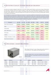
Through a DMX modulator (code8502002DMX) you can control 3 channels,which corr<strong>es</strong>pond to red, green and blueof all the projectors connected to this DMXmodulator. In this way, 256 different levelscan be achieved for each colour. Bymixing the three colours, you can obtainover 16 million colours. You should assignan addr<strong>es</strong>s to each modulator, which willdetermine the 3 channels it can control(see Assignment of DMX addr<strong>es</strong>s).Selection ofDMX directionYellow LED = Power OnGreen LED = DMX communicationLine terminationThe two switch<strong>es</strong> should be in theON position in the DMX receiverplaced at the termination of theline.Power input (12Vac) Connections 8and 9DMX Input: GND Connection 18- Connection 19+ Connection 20DMX Output: GND Connection 21- Connection 22+ Connection 23
Assignment of DMX addr<strong>es</strong>sThe modulator us<strong>es</strong> 3 DMX channels: red, green and blue, corr<strong>es</strong>ponding to the base, base +1 and base +2addr<strong>es</strong>s<strong>es</strong> r<strong>es</strong>pectively.A 9-position DIP switch is used to configure the DMX base addr<strong>es</strong>s. The DMX addr<strong>es</strong>s corr<strong>es</strong>ponds to binary value ofthe switch<strong>es</strong> plus one. To find the addr<strong>es</strong>s in the Table 1, pag. 15, look for the configuration of switch<strong>es</strong> 1 to 5 on theleft-hand side of the table, and the configurations of switch<strong>es</strong> 6 to 9 above the table. “0” means OFF, and “1” meansON.Example: Base addr<strong>es</strong>s = 9Red: Channel 9Green : Channel 10Blue : Channel 11DMX line terminationBase addr<strong>es</strong>s = 12Red : Channel 12Green : Channel 13Blue : Channel 14At the last terminal of the DMX line, the line termination should be activated. At the remaining terminals, the linetermination should be deactivated.In DMX modulators (code 8502002DMX) the line termination is activated with the 2-position DIP switch:Deactivated: SW 1 OFFSW 2 OFFActivated: SW 1 ONSW 2 ONDMX communications busThe DMX signal can be affected by electrical noise from other signals. It is recommended to install the DMX bus awayfrom electric cabl<strong>es</strong> and other interferenc<strong>es</strong>.The maximum length of the DMX bus is around 100 m., although it vari<strong>es</strong> depending on the conditions of eachinstallation. In adverse conditions, repeaters (splitters) (code 41645) should be installed in longer lengths or linebranch<strong>es</strong>.The DMX signal is transmitted from equipment to equipment through a “daisy chain” type connection, where theequipment is connected in a chain. The DMX cable with the original signal, leav<strong>es</strong> the DMX controller and is sent tothe first equipment of the DMX link. From the first equipment, the signal go<strong>es</strong> to the next one and so on. The DMXline is terminated in the last equipment (see next section). Different equipment can be connected at any point of theline whatever the assigned addr<strong>es</strong>s.It is not possible to connect more than one DMX controller in the same DMX bus.The cable used should be suitable for this type of signal: shielded, twisted pair with a nominal impedance of 120 ohms(80 - 150) and low capacitance, with a minimum thickn<strong>es</strong>s equivalent to 24 AWG.
7. TROUBLESHOOTINGProblems Usual caus<strong>es</strong> SolutionsThe yellow LED in the DMXmodulator do<strong>es</strong> not light upCurrent is not reaching theequipmentCheck the mains socket (230 Vac)and the 12 Vac power lineThe green LED in the DMXmodulator do<strong>es</strong> not light upThe projectors do not r<strong>es</strong>pond tothe orders from the DMX controlleror the colours do not coincide withthose requiredThe projectors change colour or goout for a few momentsFaulty DMX signalIncorrect configuration of themodulator switchFaulty power supply in theprojectors or in the DMX modulatorCheck the installation of the DMXline. Only the line termination ofthe last DMX equipment of theDMX communications bus shouldbe activated (2-position DIPswitch)Check that the channels assignedto the modulator (9-position DIPswitch) corr<strong>es</strong>pond to thoseenabled in the DMX controllerCheck the 12Vac power supply lineof the projectors and the DMXmodulatorIf you are unable to solve the problem with th<strong>es</strong>e instructions, contact the technical department of LT.8. SAFETY WARNINGS:• Avoid making contact with the electric voltage.• Comply with the current standards regarding accident prevention.• In this regard, the IEC 364-7-702 standards must be observed: WIRING IN BUILDINGS SPECIAL WIRINGSWIMMING POOLS• All maintenance operations should be performed with the lamp disconnected from the Mains.• Do not handle with wet feet.• The manufacturer is not r<strong>es</strong>ponsible in any circumstanc<strong>es</strong> for assembly, installation or start-up of anyelectric components which have been inserted or handled at locations other than its own premis<strong>es</strong>.9. ENVIRONMENTAL INFORMATIONProc<strong>es</strong>sing of electrical and electronic equipment after their period of use (Only applicable in the E.U.)Our goods are d<strong>es</strong>igned and manufactured using top quality materials and components, which areenvironment-friendly and which can be reused and recycled. This symbol, marked on the equipmentor packaging, means that this equipment can not be proc<strong>es</strong>sed as normal dom<strong>es</strong>tic waste. Youshould hand it in to the technician who installs the new equipment or at special collection points forelectric and electronic equipment. Recycling this equipment do<strong>es</strong> not cost you anything and byseparating it from other waste, you are helping to prevent negative consequenc<strong>es</strong> for theenvironment and for people’s health by avoiding incorrect handling. Help us to pr<strong>es</strong>erve theEnvironment. Thank you.For detailed information on how to correctly dismantle this equipment for recycling, please contactus through info@adre.<strong>es</strong>7
ESPAÑOLIMPORTANTE: El manual de instruccion<strong>es</strong> que usted tiene en sus manos, contiene informaciónfundamental acerca de las medidas de seguridad a adoptar a la hora de la instalación y la pu<strong>es</strong>taen servicio. Por ello, <strong>es</strong> impr<strong>es</strong>cindible que tanto el instalador como el usuario lean lasinstruccion<strong>es</strong> ant<strong>es</strong> de pasar al montaje y la pu<strong>es</strong>ta en marcha.Conserve <strong>es</strong>te manual para futuras consultas acerca del funcionamiento de <strong>es</strong>te aparato.Para conseguir un óptimo rendimiento de la Lámpara Subacuática de LEDS PAR56 DMX, <strong>es</strong> convenienteobservar las instruccion<strong>es</strong> que se indican a continuación:1. COMPRUEBE EL CONTENIDO DEL EMBALAJE:• Lámpara de leds• Manual de instruccion<strong>es</strong>2. CARACTERÍSTICAS GENERALES:Esta lámpara ha sido diseñada para utilizarse totalmente sumergida. Se trata de un aparato eléctrico de clase III conuna muy baja tensión de seguridad (12 V con corriente alterna). Según norma EN 50065 la lámpara <strong>es</strong> de clase 116.La lámpara cumple con el grado de protección IPX8, con una profundidad de inmersión nominal de 2 m.Esta lámpara cumple con las normas internacional<strong>es</strong> de seguridad de luminarias, en <strong>es</strong>pecial la norma EN 60598-2-18: LUMINARIAS PARTE 2: REQUERIMIENTOS PARTICULARES SECCIÓN 18 LUMINARIAS PARA PISCINAS YAPLICACIONES SIMILARES.Debe asegurarse que bajo ningún concepto la tensión que reciba la lámpara sea superior a 12V.El fabricante en ningún caso se r<strong>es</strong>ponsabiliza del montaje, instalación o pu<strong>es</strong>ta en funcionamiento de cualquiermanipulación o incorporación de component<strong>es</strong> eléctricos que no se hayan llevado a cabo en sus instalacion<strong>es</strong>.3. INSTALACIÓN GENERAL:• Para iluminar claramente una piscina se recomienda instalar una lámpara cada 20 m 2 de superficie de agua. Enpiscinas <strong>es</strong>pecialmente profundas, será nec<strong>es</strong>ario una lámpara cada 25 m 3 de volumen de agua• Las cajas de conexión deben <strong>es</strong>tar al menos a 2 m. del borde l<strong>es</strong> la piscina o instalación acuática.• El transformador de 230/12V que alimenta la lámpara debe <strong>es</strong>tar instalado a una distancia de 3,5 m. del borde dela piscina o instalación acuática.• Las canalizacion<strong>es</strong> instaladas a menos se 3,5 m del borde de la piscina no pueden tener ningún rev<strong>es</strong>timiento nicubierta metálica.ATENCIÓNLOS AGUJEROS DE LA PARTE POSTERIOR DE LA LÁMPARA (FIG. 1) DEBEN ESTAR LIBRES EN ELMONTAJE CON EL PROYECTOR PARA QUE PUEDA ENTRAR AGUA EN EL INTERIOR Y OBTENER ASÍ UNOPTIMO RENDIMIENTO DE LA LÁMPARA.La lámpara únicamente debe funcionar sumergida y fijada a las pared<strong>es</strong> vertical<strong>es</strong> de la piscina. La lámpara vaprovista de una protección térmica que, en caso de un exc<strong>es</strong>o de temperatura, reduce el nivel de iluminación paraevitar sobrecalentamientos.Evitar instalar las líneas de alimentación de 12Vac de las lámparas y modulador<strong>es</strong> cerca de posibl<strong>es</strong> interferenciaseléctricas de otras señal<strong>es</strong>.
En una instalación con longitud<strong>es</strong> grand<strong>es</strong> de línea de alimentación <strong>es</strong> preferible alargar la línea de 230Vac e instalarlos transformador<strong>es</strong> cerca de los proyector<strong>es</strong> y, si <strong>es</strong> nec<strong>es</strong>ario, alargar la línea de 12Vac hacia el modulador DMXque controla los proyector<strong>es</strong>:Según el <strong>es</strong>quema contiguo, para un correcto funcionamiento las seccion<strong>es</strong> de los cabl<strong>es</strong> tienen que ser lasapropiadas en función de la longitud del cable. Las seccion<strong>es</strong> y longitud<strong>es</strong> para una línea en la que solamentecuelgue un modulador, sin ningún proyector, son las siguient<strong>es</strong>:Lmod (m)Sección150 - 300 2,5mm² Cu0 - 150 1,5mm² CuPara la línea en la que cuelgan los proyector<strong>es</strong> las seccion<strong>es</strong> y longitud<strong>es</strong> son las siguient<strong>es</strong>:1 proyector en la líneaL.Proyector (m)Sección55 – 90 10mm² Cu35 – 55 6mm² Cu20 – 35 4mm² Cu14 – 20 2,5mm² Cu0 – 14 1,5mm² Cu5 proyector<strong>es</strong> en la líneaL.Proyector (m)Sección10 - 18 10mm² Cu7 - 10 6mm² Cu4 - 7 4mm² Cu0 - 4 2,5mm² Cu10 proyector<strong>es</strong> en la línea2 proyector<strong>es</strong> en la líneaL.Proyector (m)Sección25 – 45 10mm² CuL.Proyector (m)Sección0 - 9 10mm² Cu18 - 25 6mm² Cu10 - 18 4mm² Cu7 - 10 2,5mm² Cu0 - 7 1,5mm² CuEn una misma línea se pueden colgar modulador y proyector<strong>es</strong>:9
4. MONTAJE:Para realizar el montaje de la lámpara PAR56 de leds en un proyector subacuático con una lámpara deincand<strong>es</strong>cencia debe seguir los siguient<strong>es</strong> pasos:1. Asegurarse que la lámpara NO recibe tensión eléctrica.2. Extraer el conjunto de lámpara y parte del proyector al borde de la piscina. (<strong>es</strong>ta operación la encontrarádebidamente detallada en el manual del proyector) (Fig. 2)3. D<strong>es</strong>montar las piezas nec<strong>es</strong>arias del proyector para extraer la lámpara de incand<strong>es</strong>cencia (<strong>es</strong>ta operación laencontrará debidamente detallada en el manual del proyector) (Fig. 3)4. D<strong>es</strong>tornillar los dos tornillos que realizan la conexión eléctrica de la lámpara PAR 56 de incand<strong>es</strong>cencia. (Fig. 4)5. Colocar la lámpara de Leds PAR 56 adquirida, realizando la conexión eléctrica con los dos tornillos de conexión.(Fig. 5)6. Montar el proyector <strong>es</strong> su posición inicial. (<strong>es</strong>ta operación la encontrará debidamente detallada en el manual delproyector)7. Conectar el proyector a la red eléctrica.5. MANTENIMIENTO:Esta lámpara no nec<strong>es</strong>ita de ningún tipo de mantenimiento, si detectan que la lámpara no funciona correctamente porfavor pónganse con nu<strong>es</strong>tro departamento de atención al cliente.EL PRODUCTO NO CONTIENE ELEMENTOS MANIPULABLES, DESMONTABLES O SUBSTITUIBLES POR ELUSUARIO, ESTÀ PROHIBIDO ACCEDER AL INTERIOR DEL PRODUCTO, SE PERDERIA LA GARANTIA DELPRODUCTO.6. SISTEMAS DE CONTROL DE LAS LAMPARAS DE LEDSEsta lámpara ha sido diseñada para funcionar únicamente con control DMX y con los modulador<strong>es</strong> DMX de LT(código 8502002DMX). No funciona con ningún otro sistema de control.La lámpara PAR56 utiliza 3 canal<strong>es</strong> DMX, uno para cada uno de los 3 color<strong>es</strong> primarios (rojo, verde y azul). Laconfiguración de la dirección DMX se realiza d<strong>es</strong>de el modulador. Un único modulador podría controlar un máximo de15 lámparas. Para disponer de un control independiente cada lámpara deberá disponer de su propio transformador ymodulador. Y a los distintos modulador<strong>es</strong> se l<strong>es</strong> deberá asignar canal<strong>es</strong> no superpu<strong>es</strong>tos con los otros modulador<strong>es</strong>.El control de la lámpara se realiza mediante un modulador DMX, que recibe las órden<strong>es</strong> de un controlador DMX (porejemplo los controlador<strong>es</strong> OnDMX, 8502006, o OnDMX Pro, 8502007) y las transmite a la lámpara. El interfazOnDMX o OnDMX Pro se conecta a todos los terminal<strong>es</strong> DMX (ej. modulador DMX código 8502002DMX) de lainstalación mediante el cable DMX (código 41646) tal y como se puede observar en la imagen. Todos los terminal<strong>es</strong>DMX se conectan en serie utilizando un único bus de comunicacion<strong>es</strong>, el último terminal DMX de la línea debeconfigurarse (ver Terminación de línea DMX) para indicar que <strong>es</strong> el último terminal del bus de comunicacion<strong>es</strong>.La lámpara permanecerá apagada mientras no se reciba señal de control del controlador DMX del sistema.Ejemplo de sistema con modulador<strong>es</strong> DMX para proyector<strong>es</strong> con lámpara PAR56 y alimentador<strong>es</strong> DMX (código8502003DMX) para proyector<strong>es</strong> Mini LED (código 8502030):10
Mediante un modulador DMX (código8502002DMX) podemos controlar 3canal<strong>es</strong> que corr<strong>es</strong>ponderán a loscolor<strong>es</strong> rojo, verde y azul de todos losproyector<strong>es</strong> conectados a dichomodulador DMX. De <strong>es</strong>te modo sepueden conseguir 256 nivel<strong>es</strong> distintospara cada color. Mezclando los tr<strong>es</strong>color<strong>es</strong> se pueden obtener más de 16millon<strong>es</strong> de color<strong>es</strong>. A cada moduladorle debemos asignar una dirección quenos determinará los 3 canal<strong>es</strong> que <strong>es</strong>tepodrá controlar (ver Asignación dedirección DMX).Selección de ladirección DMXLED amarillo = Power OnLED verde = DMX communicationTerminación lineaLos dos interruptor<strong>es</strong> deben <strong>es</strong>taren posición ON en el receptor DMXcolocado al final de la línea.Entrada alimentación (12Vac) Conexion<strong>es</strong> 8 y 9Entrada DMX: GND Conexión 18- Conexión 19+ Conexión 2011
Salida DMX: GND Conexión 21- Conexión 22+ Conexión 23Asignación de dirección DMXEl modulador utiliza 3 canal<strong>es</strong> DMX: rojo, verde y azul, corr<strong>es</strong>pondiendo a las direccion<strong>es</strong> base, base + 1 y base + 2,r<strong>es</strong>pectivamente.Para configurar la dirección base DMX se usa el DIP switch de 9 posicion<strong>es</strong>. La dirección DMX corr<strong>es</strong>ponde al valorbinario de los switch más uno. Para encontrar la dirección en la Tabla 1, pag 15, mirar la configuración de los switch1 a 5 a la izquierda de la tabla y la configuración de los switch 6 a 9 encima de la tabla. “0” significa OFF y “1” significaON.Ejemplo: Dirección base = 9Rojo : Canal 9Verde : Canal 10Azul : Canal 11Dirección base = 12Rojo : Canal 12Verde : Canal 13Azul : Canal 14Terminación de línea DMXEn el último terminal de la línea DMX la terminación de línea tiene que <strong>es</strong>tar activada. En el r<strong>es</strong>to, la terminación delínea tiene que <strong>es</strong>tar d<strong>es</strong>activada.En los modulador<strong>es</strong> DMX (código 41107) la terminación de línea se activa con el DIP switch de 2 posicion<strong>es</strong>:D<strong>es</strong>activada:Activada:SW 1 OFFSW 2 OFFSW 1 ONSW 2 ONBus de comunicacion<strong>es</strong> DMXLa señal DMX se puede ver afectada por ruidos eléctricos de otras señal<strong>es</strong>. Es aconsejable instalar el bus DMXseparado de los cabl<strong>es</strong> de electricidad y otras posibl<strong>es</strong> interferencias.La máxima longitud del bus DMX <strong>es</strong>tá alrededor de los 100m aunque varía en función de las condicion<strong>es</strong> de cadainstalación. Para condicion<strong>es</strong> adversas, longitud<strong>es</strong> más grand<strong>es</strong> o bifurcacion<strong>es</strong> de la línea habrá que instalarrepetidor<strong>es</strong> (splitter) (código 41645).La señal DMX se transmite de equipo a equipo a través de una conexión de tipo "daisy chain", donde los equipos seconectan en cadena. El cable DMX con la señal original sale de un controlador DMX y <strong>es</strong> enviada al primer equipo delenlace DMX. Del primer equipo la señal va al siguiente y así suc<strong>es</strong>ivamente. En el último equipo se termina la líneaDMX (ver siguiente apartado). Los diferent<strong>es</strong> equipos se pueden conectar en cualquier punto de la líneaindependientemente de la dirección asignada.No se puede conectar más de un controlador DMX en el mismo bus DMX.El cable usado tiene que ser el adecuado para <strong>es</strong>te tipo de señal: par trenzado apantallado con impedancia nominalde 120 ohmios (80 – 150) y baja capacitancia, con un grosor mínimo equivalente a 24 AWG.12
7. PROBLEMAS / SOLUCIONESProblemas Causas habitual<strong>es</strong> Solucion<strong>es</strong>No se enciende el LED amarilloen el modulador DMXNo se enciende el LED verde enel modulador DMXLos proyector<strong>es</strong> no r<strong>es</strong>ponden alas órden<strong>es</strong> del controlador DMXo los color<strong>es</strong> no coinciden con losd<strong>es</strong>eadosLos proyector<strong>es</strong> cambian de coloro se apagan por momentosNo llega corriente al equipoSeñal DMX defectuosaConfiguración de los switch delmodulador erróneaAlimentación defectuosa en losproyector<strong>es</strong> o en el modulador DMXRevise la toma de red (230Vac) yla línea de alimentación de 12VacRevise la instalación de la líneaDMX. Solamente el último equipoDMX del bus de comunicacion<strong>es</strong>DMX tiene que tener laterminación de línea activada(DIP switch de 2 posicion<strong>es</strong>)Revise que los canal<strong>es</strong>asignados al modulador (DIPswitch de 9 posicion<strong>es</strong>) coincidancon los habilitados en elcontrolador DMXRevise la línea de 12Vac dealimentación de los proyector<strong>es</strong> yel modulador DMXEn caso que el problema no sea r<strong>es</strong>uelto con alguna de <strong>es</strong>tas medidas póngase en contacto con el departamentotécnico de LT.7. ADVERTENCIAS DE SEGURIDAD:• Se debe evitar entrar en contacto con la tensión eléctrica.• Se deben r<strong>es</strong>petar las normas vigent<strong>es</strong> para la prevención de accident<strong>es</strong>.• A tal r<strong>es</strong>pecto, se deben cumplir las normas IEC 364-7-702: INSTALACIONES ELECTRICAS EN EDIFICIOS.INSTALACIONES ESPECIALES. PISCINAS.• Cualquier operación de mantenimiento debe realizarse con el proyector d<strong>es</strong>conectado de la red.• No manipular con los pi<strong>es</strong> mojados.• La lámpara <strong>es</strong>tá diseñada PARA USAR ÚNICAMENTE SUMERGIDA EN AGUA y <strong>es</strong>tá concebida PARAFUNCIONAR ÚNICAMENTE CON UN TRANSFORMADOR DE SEGURIDAD.8. INFORMACIÓN MEDIOAMBIENTALTratamiento de equipos eléctricos y electrónicos d<strong>es</strong>pués de su vida útil (Solo aplicable en la U.E.)Nu<strong>es</strong>tros productos <strong>es</strong>tán diseñados y fabricados con material<strong>es</strong> y component<strong>es</strong> de alta calidad,r<strong>es</strong>petuosos con el medio ambiente, que pueden ser reutilizabl<strong>es</strong> y reciclados. Este símbolo,marcado en su equipo o embalaje, significa que <strong>es</strong>te equipo no puede ser tratado como un r<strong>es</strong>iduodoméstico normal. Usted debe entregar al técnico que instale el nuevo equipo o bien depositar enpuntos de recogida d<strong>es</strong>tinados a equipos eléctricos y electrónicos. La g<strong>es</strong>tión del reciclaje de <strong>es</strong>teequipo <strong>es</strong> completamente gratuita para usted y separando <strong>es</strong>te equipo del r<strong>es</strong>to de r<strong>es</strong>iduos <strong>es</strong>tácontribuyendo a evitar consecuencias negativas para el medio ambiente y la salud de las personasevitando una manipulación incorrecta. Ayúdennos a conservar el Medioambiente, gracias.Para recibir información detallada de como realizar el correcto d<strong>es</strong>montaje de <strong>es</strong>te equipo para su reciclaje pónganseen contacto con nosotros a través de info@adre.<strong>es</strong>13
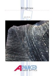
Fig. 1 Fig. 2Fig. 3Fig. 4Fig. 514
TABLE - TABLA 1DIP switch0 = OFF1 = ON#9 0 0 0 0 0 0 0 0 1 1 1 1 1 1 1 1#8 0 0 0 0 1 1 1 1 0 0 0 0 1 1 1 1#7 0 0 1 1 0 0 1 1 0 0 1 1 0 0 1 1#6 0 1 0 1 0 1 0 1 0 1 0 1 0 1 0 1#1 #2 #3 #4 #50 0 0 0 0 1 33 65 97 129 161 193 225 257 289 321 353 385 417 449 4811 0 0 0 0 2 34 66 98 130 162 194 226 258 290 322 354 386 418 450 4820 1 0 0 0 3 35 67 99 131 163 195 227 259 291 323 355 387 419 451 4831 1 0 0 0 4 36 68 100 132 164 196 228 260 292 324 356 388 420 452 4840 0 1 0 0 5 37 69 101 133 165 197 229 261 293 325 357 389 421 453 4851 0 1 0 0 6 38 70 102 134 166 198 230 262 294 326 358 390 422 454 4860 1 1 0 0 7 39 71 103 135 167 199 231 263 295 327 359 391 423 455 4871 1 1 0 0 8 40 72 104 136 168 200 232 264 296 328 360 392 424 456 4880 0 0 1 0 9 41 73 105 137 169 201 233 265 297 329 361 393 425 457 4891 0 0 1 0 10 42 74 106 138 170 202 234 266 298 330 362 394 426 458 4900 1 0 1 0 11 43 75 107 139 171 203 235 267 299 331 363 395 427 459 4911 1 0 1 0 12 44 76 108 140 172 204 236 268 300 332 364 396 428 460 4920 0 1 1 0 13 45 77 109 141 173 205 237 269 301 333 365 397 429 461 4931 0 1 1 0 14 46 78 110 142 174 206 238 270 302 334 366 398 430 462 4940 1 1 1 0 15 47 79 111 143 175 207 239 271 303 335 367 399 431 463 4951 1 1 1 0 16 48 80 112 144 176 208 240 272 304 336 368 400 432 464 4960 0 0 0 1 17 49 81 113 145 177 209 241 273 305 337 369 401 433 465 4971 0 0 0 1 18 50 82 114 146 178 210 242 274 306 338 370 402 434 466 4980 1 0 0 1 19 51 83 115 147 179 211 243 275 307 339 371 403 435 467 4991 1 0 0 1 20 52 84 116 148 180 212 244 276 308 340 372 404 436 468 5000 0 1 0 1 21 53 85 117 149 181 213 245 277 309 341 373 405 437 469 5011 0 1 0 1 22 54 86 118 150 182 214 246 278 310 342 374 406 438 470 5020 1 1 0 1 23 55 87 119 151 183 215 247 279 311 343 375 407 439 471 5031 1 1 0 1 24 56 88 120 152 184 216 248 280 312 344 376 408 440 472 5040 0 0 1 1 25 57 89 121 153 185 217 249 281 313 345 377 409 441 473 5051 0 0 1 1 26 58 90 122 154 186 218 250 282 314 346 378 410 442 474 5060 1 0 1 1 27 59 91 123 155 187 219 251 283 315 347 379 411 443 475 5071 1 0 1 1 28 60 92 124 156 188 220 252 284 316 348 380 412 444 476 5080 0 1 1 1 29 61 93 125 157 189 221 253 285 317 349 381 413 445 477 5091 0 1 1 1 30 62 94 126 158 190 222 254 286 318 350 382 414 446 478 5100 1 1 1 1 31 63 95 127 159 191 223 255 287 319 351 383 415 447 479 5111 1 1 1 1 32 64 96 128 160 192 224 256 288 320 352 384 416 448 480 512TABLE - TABLA 115
Advanced R<strong>es</strong>earch, S.L.GB PRODUCTS:E PRODUCTOS: 8502029DMXDECLARATION CE OF CONFORMITYThe products listed above are in compliance with:Electromagnetic Compatibility Directive 89/336/EEC.Low Voltage Directive 73/23/EEC.European Standard EN 60598-1, EN 60598-2-18, and all itsmodifications.DECLARACION CE DE CONFORMIDADLos productos arriba enumerados se hallan conform<strong>es</strong> con:Directiva de compatibilidad electromagnética 89/336/CEE.Directiva de equipos de baja tensión 73/23/CEE.Normativa Europea EN 60598-1, EN 60598-2-18, en todas susmodificacion<strong>es</strong>.Advanced R<strong>es</strong>earch, S.L.Castillejos, 42708024Barcelona(SPAIN)16
LED-STRAHLUNGNICHT IN DEN STRAHL BLICKENLED KLASSE 2EN 60825-1:1994+A2:2001+A1:200235604P ≤ 60Wλ =435nm - 640,5nm17
• TECHNICAL CHARACTERISTICS• CARACTERISTICAS TECNICASDESCRIPTIONRated voltage / Tensión nominalCurrent suply / Tipo de corrientePower / PotenciaProtection / Protección12 VAC60WCLASE III IPX8TO BE USED ONLY WITH A SECURIY TRANSFORMER EN 60472PARA USO EXCLUSIVO CON TRANSFORMADOR DE SEGURIDAD EN 60472We r<strong>es</strong>erve to change all or part of the articl<strong>es</strong> or contents of this document, without priornoticeNos r<strong>es</strong>ervamos el derecho de cambiar total o parcialmente las características de nu<strong>es</strong>trosartículos o contenido de <strong>es</strong>te documento sin previo aviso.8502029DMX-MMade in ECAdvanced R<strong>es</strong>earch, S.L.Castillejos, 42708024 Barcelona (Spain)info@adre.<strong>es</strong>http://www.adre.<strong>es</strong>20