2200AS - Universal Sewing Supply
2200AS - Universal Sewing Supply
2200AS - Universal Sewing Supply
- No tags were found...

Create successful ePaper yourself
Turn your PDF publications into a flip-book with our unique Google optimized e-Paper software.
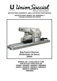
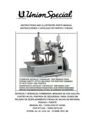
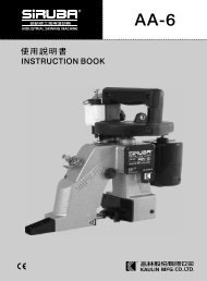
INSTRUCTIONS, ENGINEER’S AND ILLUSTRATED PARTSMANUALINSTRUCCIONES, MANUAL DEL INGENIERO Y LISTADOILUSTRADO DE PARTESCLASS 2200 - PORTABLE BAG CLOSING MACHINESCLASE 2200 - MAQUINA CERRADORA DE SACOS, PORTATILMANUAL NO. / CATALOGO NO. G283FOR STYLES / PARA ESTILOS2200A, B, F, M, AS, AA, BA, FA, MA, AAS, MB, MAB2200AZ4015, AAZ4015, AZ4015FAN, AAZ4015FAN
MANUAL NO. G283INSTRUCTIONS FOR 2200 SERIES MACHINESSixth Edition Copyright 2003byUnion Special GmbH Rights Reserved in AllCountriesPrinted in GermanyCATALOGO NO. G283 EINSTRUCCIONES PARA MAQUINAS DE LA SERIE2200Sexta Edición Propiedad Literaria 2003por Union Special GmbH Derechos Reservados entodos los paísesImpreso en AlemaniaPREFACEThis manual has been prepared to guide you whileoperating 2200 series machines and arranged to simplifyordering spare parts.INTRODUCCIONEste manual fue preparado para guiar al usuario en laoperación de maquinas de la serie 2200 y ayudar parasimplificar la elaboración de los pedidos de los repuestos.This manual explains in detail the proper settings foroperation of the machines. Illustrations are used to showthe adjustments and reference letters are used to pointout specific items discussed.Careful attention to the instructions and cautions foroperating and adjusting these machines will enable youto maintain the superior performance and reliabilitydesigned and built into every Union Special bag closingmachine.Adjustments and cautions are presented in sequence sothat a logical progression is accomplished. Someadjustments performed out of sequence may have anadverse effect on the function of the other related parts.This manual has been comprised on the basis of availableinformation. Changes in design and / or improvementsmay incorporate a slight modification of configuration inillustrations or cautions.On the following pages will be found illustrations andterminology used in describing the instructions and theparts for your machine.In addition to the instructions and the mandatory rulesand regulations for accident prevention and enviromentalprotection in the country and place of use of the machine/ unit , the generally recognized technical rules for safeand proper working must also be observed.The instructions are to be supplemented by the respectivenational rules and regulations for accidents preventionand enviromental protection.Este manual explica detalladamente los ajustes para laoperación de la maquina. Las ilustraciones sirven parademostrar los ajustes y las letras en referencia indicanlos puntos específicos discutidos.Una cuidadosa atención a las instrucciones y lasprecauciones operando y ajustando estas maquinas leva a permitir mantener el mejor funcionamiento y laconfiabilidad que caracteriza las maquinas cerradorasde sacos de Union Special.Los ajustes y precauciones son presentados ensecuencia para que se consiga una progresión lógica.La ejecución de algunos ajustes fuera de la secuenciapuede causar un efecto adverso para el funcionamientode otras partes relacionadas.Este manual se comprende a base de la informaciónactual. Cambios en diseño y/o mejoras pueden significarleves modificaciones de la configuración de lasilustraciones o precauciones.En las paginas siguientes se encuentran ilustraciones yterminologías usadas en la descripción de lasinstrucciones y las piezas de la maquina.Adicionalmente a las instrucciones, las reglas yregulaciones obligatorias para prevenir accidentes y laprotección ambiental del país y lugar donde se encuentrala maquina/unidad, hay que considerar las reglastécnicas para un trabajo seguro y adecuado.Las instrucciones hay que complementarlas con lasrespectivas reglas y regulaciones nacionales contraaccidentes y protección del ambiente.2
TABLE OF CONTENTSPageINDICEPáginaSAFETY RULES 4 - 5INDICACIONES DE SEGURIDADIDENTIFICATION OF MACHINES 5IDENTIFICACION DE LAS MAQUINASMACHINE DESCRIPTION, STYLES OF MACHINES 6 - 7DESCRIPCION Y ESTILOS DE MAQUINASNEEDLES 8AGUJASOPERATING INSTRUCTIONS 9 - 12INSTRUCCIONES DE OPERACIONPUTTING INTO SERVICE, OPERATING 9OPERACION Y PUESTA EN MARCHATHREADING, THREAD TENSION, PRESSER FOOT PRESSURE 10ENHEBRADO, TENSION DEL HILO, PRESION DEL PIE PRANSATELATHREADING DIAGRAM CLASS 2200 11DIAGRAMA DE ENHEBRADO PARA CLASE 2200CHANGING THE NEEDLE 12CAMBIO DE LA AGUJAMAINTENANCE 12 - 13MANTENIMIENTOOILING DIAGRAM CLASS 2200 13DIAGRAMA DE ACEITE PARA CLASE 2200INSTRUCTIONS FOR MECHANICS 14 - 16INSTRUCCIONES PARA MECANICOSDISASSEMBLING AND ASSEMBLING THE MOTOR 16DESARMANDO Y ARMANDO EL MOTORORDERING WEAR AND SPARE PARTS 17ORDENANDO PARTES Y PIEZAS DE REPUESTOEXPLODED VIEWS AND DESCRIPTION OF PARTS 18 - 25VISTA Y DESCRIPCION DE LAS PARTES Y PIEZASHOUSING ASSEMBLY, BUSHINGS FOR LOOPER SHAFT, MOUNTING INSTRUCTIONS 18 - 19CONJUNTO DEL COJINETE, BOCINAS PARA EL CIGUEÑAL, INSTRUCCIONES DE MONTAJECOVER ASSEMBLY, THREAD CONE SUPPORT, UPPER FEED DRIVE MECHANISM, 20 - 21PRESSER FOOT LEVER, UPPER FEED DOG, PRESSER FOOT, THREAD GUIDESCONJUNTO DE LA CUBIERTA, SOPORTE DEL CONO DE HILO, MECANISMO SUPERIOR DE ALIMENTACIONPALANCA LEVANTA PRENSATELAS, DIENTE SUPERIOR, PIE PRENSATELAS, GUIA HILOSHOUSING, CRANKSHAFT, NEEDLE-, LOOPER-, FEED- AND CHAINCUTTER DRIVE 22 - 25MECHANISM, FEED DOG, LOOPER, THROAT PLATE, COVERSCOJINETE, CIGUEÑAL, MECANISMO ACCIONADOR DEL LOOPER, ALIMENTADORY CORTADOR DE CADENETA, DIENTE ALIMENTADOR, LOOPER, PLANCHA DE AGUJA, CUBIERTASTAPE FOLDER AND MECHANICAL TAPE CUTTING DEVICE 26 - 27DOBLADOR DE CINTA Y CORTADOR MECANICO DE CINTABAG CLOSING MACHINES 2200AZ4015FAN AND 2200AAZ4015FAN 28 - 29MAQUINAS CERRADORAS DE SACOS AZ4015FAN Y 2200AAZ4015FANMOTOR ASSEMBLIES 30 - 41CONJUNTO DEL MOTORACCESSORIES 42 - 43ACCESORIOSPEDESTAL 44 - 45PEDESTALTABLES FOR PEDESTAL MOUNTED STYLES 46 - 47MESAS PARA ESTILOS MONTADOS EN PEDESTALTOP LOCK SPRING BALANCER 48POLIPASTOHOW TO UNRAVEL A BAG CLOSING SEAM? 49COMO DESHACER UNA COSTURA DE SACOS?THREAD STAND PART NO. 93065C 50 - 51CONJUNTO ESTANTE PORTAHILOS PARTE NO.93065CNUMMERICAL INDEX OF PARTSINDICE NUMERICO DE PARTES 52 - 533
SAFETY RULESGeneral operating instructions1. Before putting the machines described in this manualinto service, carefully read the instructions. The startingof each machine is only permitted after taking notice ofthe instructions and by qualified operators.INDICACIONES DE SEGURIDADInstrucciones generales de operación1. Antes de poner en marcha las máquinas descritas eneste manual, hay que leer cuidadosamente las instrucciones.El arranque de cada maquina solamente se permite después dehaber leído las instrucciones y por personal calificado.2. Observe the national safety rules valid for your country.3. Each machine is only allowed to be used as foreseen.The foreseen use of the particular machine is describedin paragraph "MACHINE DESCRIPTION" of thisinstruction manual. Another use, going beyond thedescription, is not as foreseen.4. All safety devices must be in position when the machineis ready for work or in operation. Operation of themachine without the appertaining safety devices isprohibited.5. Wear safety glasses.6. In case of machine conversions and changes all validsafety rules must be considered. Conversions andchanges are made at your own risk.2. Observe las reglas nacionales de seguridad que rigen para supaís.3. La máquina solamente se puede utilizar para su uso previsto.El uso previsto esta descrito en el capitulo ESTILO DEMAQUINAS de este manual de instrucciones. Otro uso, diferentede la descripción, no esta previsto.4. Todos los dispositivos de seguridad tienen que estar en su sitiocuando la maquina este lista para trabajar u operando. Laoperación de la maquina sin los dispositivos de seguridad estaprohibida.5. Utilice lentes de seguridad.6. En el caso de una modificación de la maquina hay que tomar encuenta las reglas de seguridad. Modificaciones y cambioscorren por su riesgo.7. The warning hints in the instructions are markedwith one of these two symbols.7. Las advertencias en el manual de instrucciones estánmarcadas con las siguientes señales de aviso:Special operating instructions8. When doing the following the machine has to bedisconnected from the power supply by pulling outthe main plug.8.1 When threading needle and looper.8.2 When replacing any parts such as needlepresser foot, throat plate, looper, spreader,feed dog, needle guard,folder, fabric guideetc.8.3 When leaving the workplace and whenthe work place is unattended.8.4 When doing maintenance work.Instrucciones especiales de operación8. Para las siguientes maniobras hay que desconectar lamaquina del suministro eléctrico desconectando elenchufe principal:8.1 Enhebrando agujas y looper.8.2 Reemplazando piezas como agujas, pie prensatela, plancha de aguja, looper, dispensador, dientesde arras tre, guarda aguja, dobladilladores, etc.8.3 Cuando salga de su puesto de trabajo y no seencuentre alguien para atender la maquina.8.4 Durante trabajos de mantenimiento.4
General maintenance directions9. Maintenance, repair and conversion work (see item 8)must be done only by trained technicians orspecial skilled personnel under condsideration of theinstructions.Only genuine spare parts approved by UNIONSPECIAL have to be used for repairs. These parts aredesigned specifically for your machine andmanufactured with utmost precision to assure longlasting service.10. Any work on the electrical equipment must be done byan electrician or under direction and supervision ofspecial skilled personnel.Special maintenance directions11. Work on parts and equipment under electrical poweris not permitted. Permissible exceptions are describedin the applicable section of standard sheet EN 50 110/ VDE 0105.12. Before doing maintenance and repair work on thepneumatic equipment, the machine has to bedisconnected from the compressed air supply. Incase of existing residual air pressure afterdisconnecting from compressed air supply (e.g.pneumatic equipment with air tank), the pressure hasto be removed by bleeding. Exceptions are onlyallowed for adjusting work and function checks doneby special skilled personnel.Instrucciones generales de mantenimiento9. Mantenimiento, reparaciones y trabajos de conversión(vease No. 8) solamente pueden ser efectuados por técnicosentrenados o personal especializado bajo consideración delas instrucciones.Solamente repuestos originales y aprobados por UnionSpecial pueden ser utilizados para reparaciones.Estosrepuestos han sido diseñados especificamente para estasmáquinas, con precisión y para asegurar su máxima vida útil.10. Cualquier trabajo con el equipo eléctrico tiene que serejecutado por un electricista o bajo la supervisión de personalespecialmente entrenado.Instrucciones especiales de mantenimiento11. No esta permitido trabajar en piezas y equipos con laelectricidad conectada. Excepciones permitidas estándescritas en EN 50110 / VDE 0105.12. Antes de hacer mantenimiento o reparaciones del equiponeumático, hay que desconectar la maquina de laalimentación del aire comprimido. En el caso que exista unapresión de aire residual después de desconectar la maquina(por ejemplo equipos con tanques de aire), la presión tieneque ser eliminada abriendo las válvulas. Excepciones estánsolamente permitidas para trabajos de ajuste y revisión defunciones por personal especialmente entrenado.IDENTIFICATION OF MACHINESEach UNION SPECIAL machine is identified by a stylenumber, which is stamped into the style plate affixed tothe machine. The serial number is fixed into the castingof the machine housing.IDENTIFICACION DE LAS MAQUINASCada máquina UNION SPECIAL está identificada porun número de estilo, el cual está estampado en la placafijada a la máquina. El número de serial está troqueladoen la carcasa de la máquina.5
MACHINE DESCRIPTIONPortable bag closing machine with inegral electric motor andbuilt-in thread chain cutter.For closing filled bags and sacks as well as for stitching webs,made of jute, burlap, cotton, linen, paper, plastic, wovenpolyproylene, non-wovens or combinations of these fabrics withsingle thread chainstitch (stitch type 101*) or two thread doublelocked stitch (stitch type 401*).Combined upper and lower feed.Direct drive with an electric motor.Motor ball bearing dust proof and permanently lubricated. Heavyduty,automatic shut-off commutator brushes prevent damagesof the armature. Motor housing and handle made of fiberglassreinforcedbreak-resistant plyamide. The design of the motorhousing allows to securely put down the machine in a handyposition, when not in use.The machines are designed for switch actuated operation (S3 :40%) ! A normal sewing cycle lasts approx. 5 to 8 seconds. Perhour normally up to 200 bag can be closed.SPECIFICATIONSSeam specification: 101 SSa-1 or 401 SSa-1.<strong>Sewing</strong> capacity: up to 9 mm (3/8") or up to 24plies of paper.Stitch range:3 to 9 mm (3 to 8 1/2 SPI)Standard Setting: 8 mm (3 SPI)Feed:Upper and lower feed.Teeth cut:2.1 mm (12 teeth per inch)Standard needle: 9854G200/080(also refer to paragraph"NEEDLES").Speed:1200 to 1700 stitches perminute, depending on bagfabric.Sound pressure level at recommended operating speed (1500 rpm):79 dB (A), measurement acc. to DIN 45635-48.Weighted root mean square acceleration value at recommendedoperating speed (1500 rpm):
STYLES OF MACHINES2200A Double locked stitch, stitch type 401.Motor for 220 to 240 V, 50/60 Hz.Protector class I, with ground wire.2200B Double locked stitch, stitch type 401.Motor for 110 to 125 V, 50/60 Hz.Protector class I, with ground wire.2200F Double locked stitch, stitch type 401.Motor for 42 V, 50/60 Hz.Protection class III, safety extra-low voltage.2200M Double locked stitch, stitch type 401.Motor for 12 V DC.Protection class III, safety extra-low voltage.<strong>2200AS</strong> Double locked stitch, stitch type 401.Motor for 200 to 240 V, 50/60 Hz.Protection class II, without ground wire.2200AA Single thread chainstitch, stitch type 101.Motor for 220 to 240 V, 50/60 Hz.Protection class I, with ground wire.2200BA Single thread chainstitch, stitch type 101.Motor for 110 to 125 V, 50/60 Hz.Protection class I, with ground wire.2200FA Single thread chainstitch, stitch type 101.Motor for 42 V, 50/60 Hz.Protection class III, safety extra-low voltage.2200MA Single thread chainstitch, stitch type 101.Motor for 12 V DC.Protection class III, safety extra-low voltage.2200AAS Single thread chainstitch, stitch type 101.Motor for 220 to 240 V, 50/60 Hz.Protection class II, without ground wire.2200MB Double locked stitch, stitch type 401.Motor for 24 V DC. Protection class III, safety extra-lowvoltage, using four longlife, rechargeableNC-batteries which are integrated in a leather belt.Battery charger primary 230 V, 50 Hz included.Available extras:Additional battery belt Part No. 90195Additional battery charger Part No. 90195B2200MAB Same as 2200MB, but single thread chainstitch,stitch type 101.2200AZ4015FAN Double locked stitch, stitch type 401.Without motor, for bag closing units.Speed: up to 1500 stitches per minute.2200AAZ4015FAN Single thread chainstitch, stitch type 101.Without motor, for bag closing units.Speed: up to 1500 stitches per minute.For repair sewing machines without motor are available:2200AZ4015 <strong>Sewing</strong> machine only, without handle andmotor. Double locked stitch, stitch type 401.2200AAZ4015 <strong>Sewing</strong> machine only, without handle andmotor. Single thread chainstitch, stitch type 101.HINT:Each two thread double locked stitch machine of class 2200 can beconverted into a single thread chainstitch machine and vice versa.The conversion works have to be done only by skilled personnalunder observance ot the safety rules and under consideration of theinstructions.ESTILOS DE MAQUINAS2200A Costura de cadeneta doble, tipo 401.Motor 220 a 240 V, 50/60 Hz.Protección clase I, con cable tierra.2200B Costura de cadeneta doble, tipo 401.Motor 110 a 125 V, 50/60 Hz.Protección clase I, con cable tierra.2200F Costura de cadeneta doble, tipo 401.Motor 42 V, 50/60 Hz.Protección clase III, bajo voltaje extra seguro.2200M Costura de cadeneta doble, tipo 401.Motor 12 V DC.Protección clase III, bajo voltaje extra seguro.<strong>2200AS</strong> Costura de cadeneta doble, tipo 401.Motor 220 a 240 V, 50/60 Hz.Protección clase II, sin cable tierra.2200AA Costura de cadeneta simple, tipo 101.Motor 220 a 240 V, 50/60 Hz.Protección clase I, con cable tierra.2200BA Costura de cadeneta simple, tipo 101.Motor 110 a 125 V, 50/60 Hz.Protección clase I, con cable tierra.2200FA Costura de cadeneta simple, tipo 101.Motor 42 V, 50/60 Hz.Protección clase III, bajo voltaje extra seguro.2200MA Costura de cadeneta simple, tipo 101.Motor 12 V DC.Protección clase III, bajo voltaje extra seguro.2200AAS Costura de cadeneta simple, tipo 101.Motor 220 a 240 V, 50/60 Hz.Protección clase II, sin cable tierra.2200MB Costura de cadeneta doble, tipo 401.Motor 24 V DC.Protección clase III, bajo voltaje extra seguro.Utiliza 4 Baterias NC, recargables, integradas a la correa de cuero.Cargador de baterias 230V, 50Hz incluido.Tambien disponible:Correa de cuero con baterias, adicional Parte Nr. 90195Cargador adicional Parte Nr. 90195B2200MAB Igual a la 2200MB, pero con costura de cadeneta simple,tipo 101.2200AZ4015FAN Costura de cadeneta doble, tipo 401.Sin motor, especial para unidades cerradoras de sacos.Velocidad: 1500 Puntadas/min.2200AAZ4015FAN Costura de cadeneta simple, tipo 101.Sin motor, especial para unidades cerradoras de sacos.Velocidad: 1500 Puntadas/min.Para trabajos de reparación de maquinas sin motor, tenemosdisponible:2200AZ4015 Cabezal solo, sin mango ni motor.Costura de cadeneta doble, tipo 401.2200AAZ4015 Cabezal solo, sin mango ni motor.Costura de cadeneta simple, tipo 101.SUGERENCIA:Máquinas de costura de doble cadeneta de la clase 2200 pueden serconvertidas a máquinas de costura de cadeneta simple y viceversa.El trabajo de conversión de la máquine tiene que ser hecho porpersonal capacitado, bajo estricto cumplimiento de las reglas deseguridad y consideración de las instrucciones del fabricante.7
OPERATING INSTRUCTIONSPUTTING INTO SERVICEBefore leaving our factory each machine is carefully inspected,adjusted and given a sewing test. However, upen receipt themachine should be inspected and any damage or complaintshould be reported to Union Special or their distributor withoutdelay.Unpack the machine. Make sure that no pieces of packing aretrapped in the mechanism.Check by turning the motor handwheel in operating direction(see Fig. 2) if the machine works. A slight restistance will befelt as the feed dog rises.Loosen screw (A, Fig. 3) and set thread rod (B) so that itslower end is flush with the underside of thread cone support(C). Retighten screw (A).Check the threading of the machine. Observe the threadingdiagram Fig. 4 and paragraph "THREADING".Lubricate the machine again as per oiling diagram Fig. 5.Depending upon the operating conditions, oiling should be doneat least once a day.Check if the voltage of the sewing motor corresponds with thevoltage of the wall socket. Wall sockets for machines withground wire must be porperly grounded. Insert the plug of thepower cable into the wall socket.Start stitching on a piece of the bag material (jute, paper,polypropylene etc) by pressing the thumb switch. Continuestitching as the bag leaves the machine. This will produce athread chain, which when guided into the V-cut out of the throatplate is automatically cut by the thread chain cutting knives.Release the switch, the machine stops.NOTE: The knives only function when the machine is operating.Otherwise the thread chain will break when pulled and couldcause damage to the needle and looper.OPERATINGFor a neat, presentable closure the filled bag has to be preparedas follows:Paper, heavy gauge plastic, coated polypropylene bags:INSTRUCCIONES DE OPERACIONPUESTA EN MARCHAAntes de salir de nuestra fábrica cada máquina es cuidadosamenteinspeccionada y sometida a pruebas de costura. Sin embargo, tan prontocomo se reciba debe ser inspeccionada y cualquier daño o queja debe sernotificado inmediatamente a Union Special o al distribuidor que realizó laventa.Desempaque la máquina y verifique que no quedaron piezas del material deempaque dentro del mecanismo.Verifique que la máquina funciona girando el volante en sentido de operación(Fig. 2). Un ligera resistencia se sentirá a medida que el diente alimentadorse levanta.Suelte el tornillo (A, Fig. 3) y ajuste la varilla del hilo (B) de manera queligeramente roce la parte inferior del soporte del porta conos (C). Ajuste denuevo el tornillo (A).Verifique el enhebrado de la máquina. Revise el diagrama de enhebrado Fig.4 y el parágrafo "ENHEBRADO".Lubrique la máquina de acuerdo con el diagrama de Lubricación Fig. 5.Dependiendo de las condiciones de operación, la máquina debe ser lubricadapor lo menos una vez al día.Verifique que el voltaje del motor corresponda con el voltaje del enchufedonde se conectará la máquina. Enchufes con conexión a tierre deben seradecuadamente conectados. Finalmente, enchufe la máquina.Comienze a coser sobre un pedazo de material (Yute, Papel, Polypropileno,etc.) presionando el boton de arranque. Continue cosiendo hasta que el sacosalga de la máquina. Se producirá una cadeneta, la cual al ser guiada através del cortador en forma de V al final de la plancha de aguja se contará alpasarla por las cuchillas cortadoras. Suelte el botn de arranque y la máquinadejará de funcionar.NOTA: Las cuchillas solo cortan cuando la máquina está encendida. Tengacuidado de no halar la cadeneta con la máquina apagada, ya que puededañar la aguja y el looper.OPERACIONPara una costura limpia y presentable, el saco debe ser preparado como seseñala a continuación:Papel, plástico pesado y sacos de polypropileno:Inserte ambas manos en la boca del saco lleno y abralo. A continuación,sujete los extremos del saco y con un movimiento firme, acueste el saco ysaque el aire sobrante.Insert both hands into the opening of the filled bag and spreadit apart.Then grip both outer edges of the bag and fold with a sharpmovement the bag top forward and over to expel the air.9
Bring the bag top to the upright position so that it is flat andvertical.Bring the machine to the right hand side of the bag, approx.25 to 40 mm (1- 1 1/2") from the top.Enter the leading edge of the bag between presser foot andthroat plate.Keep a security distance of approx. 100 mm(4") between main and sewing needle!Press the thumb switch. The machine sews across the bag,requiring the operator only to keep pace by moving the handin conjunction with the sewing speed of the machine.As the machine comes off the bag guide the thread chain witha slight twist of the rist into the knives, simultaneously releasethe switch.The machine stops.This results in a short, neat thread chain at the beginning andend of the bag.Hessian, jute, woven polypropylene, cotton and net bags:These bag materials ar not stiff enough, therefore the rightleading edge of the bag has to be entered with the left handinto the machine.Keep a security distance of approx. 100 mm(4") between main and sewing needle!While sewing the operator should move the left hand to theleft side of the bag, maintaining a slight tension across the topof the bag.Enderece el saco de manera que quede en posición vertical y plano.Acerque la máquina a la parte derecha del saco, aproximadamente 25 a 40mm del tope del saco.Introduzca la esquina superior del saco entre el pie prensatelas y la planchade aguja.Mantenga una distancia de aproximdamente 100 mmentre su mano y la aguja de la máquina.!Presione el boton de arranque. La máquina coserá a través del saco,requiriendo del operador solamente mantener la velocidad moviendo la manoen conjunto con la máquina hasta el final de la costura.Cuando el saco salga de la máquina, saldrá un pedazo de cadeneta, que secorta haciendo un ligero movimiento de la muñeca hacia las cuchicllas decorte y soltando simultaneamente el boton de arranque.La maquina se para.El resultado final es una costura limpia y presentable del principio al final delsaco.Sacos de arpilla, fibra natural, Yute, Polipropileno, Algodón y Mallas Tejidas:El material de estos sacos no es lo suficientemente rigido, asi que la puntasuperior derecha del saco debe ser introducida en la maquina con ayuda dela mano izquierda.Mantenga una distancia de aproximdamente 100 mmentre su mano y la aguja de la máquina.!Mientras realiza la operación de costura, el operador debe mantener la manoizquierda a la izquierda del saco, para mantener una ligera tensión en elsaco y lograr una costura pareja.THREADINGPull out mains plug before threading!Loosen thumb screw(s) (D, Fig. 3) in the thread cone support,pull out the spool pin(s) (E) and remove the empty threadcone(s).Insert the new thread cone(s) with spool pin(s) (E) andretighten thumb screw(s) (D).Thread the machine as shown in Fig. 4.For threading the needle, turn motor handwheel in operatingdirection until the needle is in its upmost position above thethroat plate.For threading the looper (double locked stitch machines only)open the hinged cover (A, Fig. 4) and turn motor handwheel inoperating direction until the needle is in its lowest positionbelow the throat plate. Reclose hinged cover (A) afterthreading.THREAD TENSIONThe tension (L, Figs. 4 and 13) controls the looper thread andthe tension (N) controls the needle thread.Only a slight tensionshould be applied on the looper thread. The tension appliedon the needle thread depends upon the size of the thread andthe thickness of the fabric to be sewn and has to be regulatedtill the machine sews and chains off perfectly.PRESSER FOOT PRESSUREThe pressure on the presser foot should be just so strongthat the machine feeds uniformly on the fabric to be sewn.When leaving the fabric to be sewn, an uniform thread chainmust be formed.The presser foot pressure is regulated with the knurledregulating screw (B, Fig. 4).For adjustment loosen nut (C) and turn the regulating screw(B) clockwise to increase the pressure or counterclockwise todecrease the pressure.ENHEBRADODesenchufe la máquina antes de enhebrarla!Afloje los tornillos (D, Fig. 3) del soporte del porta conos, saque los pasadores(E) y retire el cono de hilo vacio.Inserte un nuevo cono de hilo, inserte los pasadores (E) y apriete de nuevolos tornillos (D).Enhebre la máquina tal como se muestra en el diagrama de la Fig. 4.Para enhebrar la aguja, mueva el volante del motor en dirección de operación,hasta que la aguja alcance su punto mas alto de recorrido sobre la planchade aguja.Para enhebrar el looper (en máquinas de costura de cadeneta doblesolamente) abra la tapa del motor (A, Fig. 4) y mueva el volante del motor endirección de operación hasta que la aguja esté en su posición más bajadebajo de la plancha de aguja . Cierre la tapa del motor nuevamente.TENSION DEL HILOEl tensor (L, Fig. 4 y 13) regula el hilo del looper y el tensor (N) regula el hilode la aguja. Solamente una ligera tensión debe ser aplicada al hilo del looper.La tensión aplicada al hilo de la aguja depende del hilo a utilizar y del grosordel material a coser, y debe ser regulada manualmente hasta que la máquinacosa perfectamente.PRESION DEL PIE PRENSATELASAl pie prensatelas se debe aplicar suficiente presión para que el dientetransportador arrastre uniformemente el material y para que salga la cadeneta.La presión del pie se regula con el tornillo estriado (B, Fig. 4).Para ajustar el pie prensatelas, suelte la tuerca (C) y gire el tornillo regulador(B) en sentido del reloj para incrementar la presión y en sentido contrariopara disminuirla.Apriete de nuevo la tuerca (C).Retighten nut (C).10
CHANGING THE NEEDLEPull out mains plug before changingthe needle!Turn motor handwheel in operating direction until the needle is in itsupmost position above the throat plate. Unthread the eye of theneedle.Loosen the screw (D, Fig. 4) for the needle and draw out the needle.Insert the shank of the new needle as far as it will go into the needleseat and with the flat on the shank facing to the front.Retighten screw (D) for the needle on the flat of the needle shankand thread the needle eye.CAMBIO DE AGUJADesenchufe la máquina antes de cambiarla aguja!Mueva el volante del motor en dirección de operación, hasta que laaguja alcance su punto mas alto de recorrido sobre la plancha deaguja. Desenhebre la aguja.Suelte el tornillo (D, Fig. 4) de la aguja y retire la aguja. Inserte laaguja de manera que la superficie plana mire hacia adelante.Asegure el tornillo (D) de la aguja en la parte plana del cabo yenhebre la aguja.MAINTENANCEMANTENIMIENTOPull out the mains plug before doingmaintenance work or before oiling!Desenchufe la máquina antes de realizar trabajosde mantenimiento y/o antes de aceitarla!OILINGThe machine has to be oiled at least once a day on the oil spots 1 to11 shown in the oiling diagram Fig. 5.Oil spots 1, 2 and 3 are especially important!Recommended oil: Mobil D.T.E., Oil Medium.This oil can be purchased from Union Special in 0.5 liter containersunder part No. G28604L or in 5 liter containers under the part No.G28604L5.CLEANINGClean the machine at least once a week from lint. For this also openhinged cover (A, Fig. 5) and the punched cover (B, Fig. 5).Reclose covers.ACEITADOLa máquina debe ser aceitada por lo menos una vez al dia en loslugares señalados del 1 al 11 en el diagrama de aceite, Fig. 5.Puntos 1,2 y 3 son sumamente importantes!Recomendamos el aceite Mobil D.T.E. Aceite Medio.Este aceite puede ser comprado de Union Special en envase de0,5 ltr. bajo número de parte G28604L o en envases de 5 ltrs. bajonúmero de parte G28604L5.LIMPIEZALimpie la máquina por lo menos una vez a la semana para mantenerlalibre de pelusas. También se recomienda abrir las cubiertas (A,Fig. 5) y (B, Fig. 5) frecuentemente para limpiar dentro del motor.Recuerde cerrar nuevamente estas cubiertas.12
INSTRUCTIONS FOR MECHANICSObserve the SAFETY RULES!SETTING THE LOOPER1. Looper for two thread double locked stitch:Set the looper (A, Fig. 6) so that the distance from the center of theneedle (B) to the point of the looper is not less than 4 mm (5/32")when the looper is at its farthest end position from the needle. Loopergauge No. 21225-4/4.4 can be used advantageously in making thissetting.2. Looper for single thread chainstitch:Set the looper (A, Fig. 6A) so that the distance from the center ofthe needle (B) to the point of the looper is not less than 3.6 mm (9/64") when the looper is at its farthest end position from the needle.Looper gauge No. 21225-9/64 can be used advantageously inmaking this setting.If adjustment is required remove plug (C, Fig. 7). Set screw forlooper shaft is accessible through thsi hole. Loosen the screw andmove the looper shaft to the right or to the left to obtain the 4 mm (5/32") respectively the 3.6 mm (9/64") distance. The looper pointshould pass as close as possible to the back of the needle withoutcontacting it. Clearance 0.08 to 0.13 mm (0.003 to 0.005 in.).Retighten screw and remount the plug.SETTING HEIGHT OF NEEDLEThe height of the needle is correct, when the top of its eye is flushwith the lower edge of the lloper, when the looper moves to the leftand its point is flush with the left side of the needle (see Fig. 8).If adjustment is necessary, loosen set screw (D, Fig. 7) and removeneedle, then loosen lock nut (E) and regulate the height adjustmentscrew (A). Now reset stop screw (B) in feed dog to maintain theadjusted feed dog height.INSTRUCCIONES PARA MECANICOSObserve las INDICACIONES DE SEGURIDAD!AJUSTE DEL LOOPER1. Looper para costura de cadeneta doble, dos hilos:Ajustar el looper (A, Fig. 6) de manera tal que la distancia entre el centrode la aguja (B) y la punta del looper no sea menos de 4 mm en el momentocuando el looper esta en su distancia máxima a la aguja. El calibrador delooper parte No. 21225-4/4.4 se recomienda para realizar este ajuste.2. Looper para costura de cadeneta sencilla:Ajustar el looper (A, Fig. 6) de manera tal que la distancia entre el centrode la aguja (B) y la punta del looper no sea menos de 3,6 mm en el momentocuando el looper esta en su distancia máxima a la aguja. El calibrador delooper parte No. 21225-4/4.4 se recomienda para realizar este ajuste.Para lograr esto se remueve la tapa (C, Fig. 7) para llegar al tornillo que fijael eje del looper. Soltar el tornillo, mover el eje del looper hacia la izquierdao hacia la derecha hasta que se logra la distancia de 4 mm . La punta dellooper deberia pasar lo mas cerca posible de la parte trasera de la gujapero sin tocarla. La altura recomendada es de 0.08 a 0.13 mm.Fijar el tornillo y montar la tapa otra vez.AJUSTE DE LA ALTURA DE LA AGUJAEl ajuste correcto de la aguja se logra cuando el tope del ojo de la agujaesté al ras con el borde inferior del looper en el momento cuando el looperse mueve hacia la izquierda y esta con su punta al ras con el borde izquierdode la aguja. (Ver Fig. 8).Para lograr esto se remueve la aguja soltando el tornillo (D, Fig. 7). Despuésse suelta la tuerca (E) y regula con el tornillo (F) la altura correcta. Fijarposición apretando otra vez la tuerca (E).SETTING THE LOWER FEED DOGThe lower feed dog is set correctly when its teeth rise slightly morethan the depth of a full tooth (approx. 1.6 mm (1/16") above thethroat plate (see Fig. 9). To raise or lower the feed dog loosen screw(A, Fig. 10) and set the feed dog to the specified height. Retightenscrew (A). Now reset stop screw (B) in feed dog to maintain theadjusted feed dog height.AJUSTE DEL DIENTE INFERIOR DE ARRASTREEl ajuste correcto del diente inferior de arrastre se logra cuando los dientessobrepasan aprox. 1,6 mm la plancha de la aguja (Ver Fig. 9). Para bajar osubir el transportador hay que soltar el tornillo (A, Fig. 10) ajustar la alturadel diente de arrastre y apretar el tornillo (A) otra vez. Ahora hay que ajustarel contra-tornillo (B) para mantener esta posición.NEEDLE GUARDSet the needle guard (C, Fig. 10) so that it just touches the needlewhen it is at its most forward point of travel. To move guard forwardor backward loosen screw (A) and move needle guard as required.Retighten screw.NOTE: Screw (A) serves also to fasten the lower feed dog. Thereforemake sure not to disturb the feed dog height when setting the needleguard.AJUSTE DEL GUARDA AGUJASFijar el guarda aguja (C, Fig. 10) de tal manera que en el punto mas avanzadode su movimiento toque levemente la aguja. Para este ajuste hay que soltarel tornillo A y mover el guarda aguja como sea necesario.NOTA: Hay que tener cuidado para no variar la altura del diente alimentador,ya que esta fijado con el mismo tornillo (A).14
SETTING OF THE KNIVES1. Fixed knife:Set the fixed knife (A, Fig. 11) so that its tip sits close to theunderside of the throat plate (B). For adjustment loosen screw(C) and move knife up or down in its holder as required.Retighten screw.2. Moving knife:Set the moving knife (D, Fig. 11) so that is just clears belowthe throat plate underside on its entire arc of travel. In the mostopen position of the knives the pilot (E) should overlap thefixed knife by 3 mm (1/8"). In cutting position of the knives thecutting edge of the moving knife should overlap the cuttingedge of the fixed knife at least 1 mm (3/64"). For adjustingmoving knife loosen screw (F) and set knife as required.Retighten screw.STITCH LENGTHTo change the stitch length, remove the cover plate located belowthe serial number of the machine. Loosen lock nut (A, Fig. 12)and turn stitch length adjusting screw (B) clockwise to shortenstitch or counterclockwise to lengthen it.After adjustment, retighten lock nut (A) and replace the cover plate.NOTE: Any change in the stitch length necessitates correspondingchange in the needle guard setting.THREAD GUIDESSet the needle thread take-up (A, Fig. 13) so that the needle threadcontacts the hook (A) just when the needle thread loop leaves thelooper point.The needle thread eyelet (B) is set correctily when the eyelet dipsabout 30° to the left.The looper thread eyelet (C) controlls the looper thread. It is setcorrectly when it takes up slack of the looper thread when thelooper moves to the right.THROAT PLATE NEEDLE HOLE SECTION FOR THINFABRICSFor closing of thin and soft fabric an auxiliary needle hole sectionon the needle hole of the throat plate is required:1 - part No. 2130 Needle hole section1 - part No. 77K ScrewFor extremely thin fabric ist is recommended to use in connectionwith these parts needle sizes 125/049 or 170/067 and sewingthread size Ne 34/4 (also refer to paragraph "NEEDLES").AJUSTE DE LAS CUCHILLAS1. Cuchilla fija:Fijar la cuchilla fija (A, Fig. 11) de tal manera que su punta esté al rascon el borde inferior de la plancha de aguja (B). Para ajustarla, soltar eltornillo (C) y mover la cuchilla hacia arriba o abajo. Apretar el tornillootra vez.2. Cuchilla móvil:Fijar la cuchilla móvil (D, Fig. 11) de tal manera que se pueda moverlibremente debajo de la plancha de la aguja. En la posición mas abiertala guía del cuchillo (E) debe sobrepasar la cuchilla fija todavía a 3 mm yen la posición del corte las cuchillas deberán sobrepasarse por lo menos1 mm. Para lograr esto hay que soltar el tornillo (F) y ajustar la posiciónde la cuchilla móvil.LÄRGO DE LA PUNTADAPara variar el largo de la puntada hay que remover la tapa debajo del serialde la maquina. Soltar la tuerca (A, Fig. 12) y girar tornillo (B) hacia la derechapara acortar la puntada y hacia la izquierda para agrandar la puntada.Después hay que apretar la tuerca (A) otra vez y cerrar la tapa.NOTA: Con cada cambio en la puntada hay que ajustar el guarda aguja.GUIA HILOSAjuste el alimentador (A, Fig. 13) del hilo de tal manera que el hilo toque elgancho (A) cuando el lazo del hilo salga de la punta del looper.El guía hilo (B) deberá estar inclinado aprox. 30 grados hacia la izquierda.El guía hilo del looper (C) está en buena posición si el hilo suelto es agarradocuando el looper se mueve hacia la derecha.ADITAMENTO PARA LA PLANCHA DE AGUJA PARA COSERMATERIALES FINOSPara materiales más finos y suaves existe un aditamento para la planchade aguja:1 - Parte No. 2130 Aditamento para el hueco de la plancha de aguja1 - Parte No. 77K TornilloEn este caso se recomienda bajar el grosor de la aguja a 125/049 ó 170/067 y utilizar hilo tamaño Ne 34/4. (Ver tambien el parrafo "AGUJAS").15
CAUTION!Pull out the mains plug before disassemblingor assembling to motor!Disassembling the motor from the sewing machine:1. Remove screw (T).2. Loosen screw (S).3. Hold the sewing machine, turn the motor clockwise until it stopsand pull it out of the sewing machine.Assembling the motor to the sewing machine:1. Turn the gears until the marks (M) on both gears are opposite toeach other, as shown, before inserting the pinion of the motor.2. Align the two holes (H) in the motor housing with the hex. headcap screws (S) in the sewing machine and push the motor andsewing machine together.3. Hold the sewing machine and turn the motor counterclockwiseuntil the parting lines (L) of the housing halves on motor andsewing machine are aligned. Tighten screws (S)4. Fasten the thread cone support with screw (T) on the handle ofthe motor housing.PRECAUCION!Desenchufe la máquina antes de montar o desmontarel motor!Desmontar el motor de la máquina de coser:1. Retire el tornillo (T).2. Suelte los tornillos (S).3. Sujete la máquina, gire el motor hacia la derecha hasta su punto máximo ysáquelo de la armazon de la máquina.Montar el motor de la máquina de coser:1. Mueva los engranajes del motor hasta que ambos queden opuestos uno aotro, como se muestra, antes de insertar el piñón del motor.2. Alinie ambos huecos (H) al cojinete del motor con los tornillos hexagonales(S) en la máquina de coser y presione hasta unirlos.3. Sujete la máquina, gire el motor hacia la izquierda hasta que las lineas divisoriasde la carcasa (L) y el motor esten alineadas.Apriete los tornillos (S).4. Asegure el porta conos con los tornillos (T) al mango de la carcasa delmotor.16
HOUSING ASSEMBLY, BUSHINGS FOR LOOPER SHAFTCONJUNTO DEL COJINETE, BOCINAS PARA EL CIGUEÑALRef. No.Ref. No.Part No.Parte No.DescriptionDescripciónAmt. Req.Cant. Req.1 - 14123456789101112131415*16*17*18*2129B99266A99266965232192219096511G41046G76099D2195N219421932193A999-104A2165D0.12165D0.22165D0.32165D0.52165D1.02165C0.521912140N2165AHousing AssemblyShoulder ScrewShoulder Screw (for screwing togetherthe housing halves)Parallel PinBushingBushingParallel PinSpring Valve OilerParallel PinBushingBushingBushingBushingPlugShim Ring 6 x 12, 0.1 mm (.004") thickShim Ring 6 x 12, 0.2 mm (.008") thickShim Ring 6 x 12, 0.3 mm (.012") thickShim Ring 6 x 12, 0.5 mm (.020") thickShim Ring 6 x 12, 1.0 mm (.040") thickShim Ring 8 x 14, 0.5 mm (.020") thickBushing for looper shaftBushing for looper shaftGearConjunto del cojineteTornillo de encuentroTornillo de encuentro (para atornillar lasmitades de la carcasa)PasadorBocinaBocinaPasadorResorte valvula aceitePasadorBocinaBocinaBocinaBocinaTapónArandela de goma 6 x 12, 0,1 mm gruesoArandela de goma 6 x 12, 0,2 mm gruesoArandela de goma 6 x 12, 0,3 mm gruesoArandela de goma 6 x 12, 0,5 mm gruesoArandela de goma 6 x 12, 1,0 mm gruesoArandela de goma 8 x 14, 0.5 mm gruesoBocina para eje del looperBocina para eje del looperEngranaje1141222412211122222111* Part of sewing machine.* Parte de máquina de coser.MOUNTING INSTRUCTIONINSTRUCCIONES DE MONTAJEHold Gear 18 and Shim Ring 15 against the Flanged Bushing 9.Measure the distance between Gear Hub and lower Bushing 10 bymeans of a Thickness Gauge. By choosing one of the above listedShim Rings 14, adjust clearance to the smallest axial play (approx.0.03 - 0.10 mm).Suejete el engranaje 18 con la Bocina para el looper 15 contrala Bocina 9. Mida la distancia entre el centro del engranaje yla Bocina baja 10. Seleccione una de las arandelas de goma14 y ajuste la distancia a la diferencia mas pequeña posible(aprox. 0,03 - 0,10 mm).19
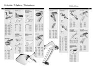
COVER ASSEMBLY, THREAD CONE SUPPORT, UPPER FEED DRIVE MECHANISM, PRESSER FOOT LEVER, UPPER FEED DOG,PRESSEER FOOT, THREAD GUIDESCONJUNTO DE LA CUBIERTA, SOPORTE DEL CONO DE HILO, MECANISMO SUPERIOR DE ALIMENTACION, PALANCA LEVANTAPRENSATELAS, DIENTE SUPERIOR, PIE PRENSATELAS, GUIA HILOSRef. No.Ref. No.Part No.Parte No.Description Descripción Amt. Req.Cant. Req.1234567891011121314151617181920212223242526272829303132333435363738394041424344454647484950515253545556575859606162G2949651292C51292F151292F8109218651292A51192GG432662159A9364041071G2163G22585A41071G2176B2158A87U2158D2158C22585A9595422585B225285175822585A51225W2189H93B2189C792289B9927021462196A99268G29493B2166A28C2176D21932196B96663932167A2168A2169A12934A2175A21439072178801752160N2179218080175212687A212087A95580Cover AssemblyTension NutTension Spring for Looper ThreadTension Spring for Needle ThreadTension DiscTension PostTension Post FerruleTension EyeletNutCoverThum ScrewNutLeaf SpringScrewNutSpring RestNeedle Thread Take-upScrewNeedle Thread EyeletLooper Thread EyeletScrewWasherScrewScrewNeedle Thread Eyelet for SingleThread Chainstitch, Type 101ScrewWasherThread Cone SupportScrewThread RodScrewSpool PinThumb ScrewConnecting RodBushingShoulder ScrewFeed Lever and Presser Foot LeverCollarSet ScrewFeed LeverBushingBushingRoll PinScrewCrankLinkShank ScrewNutPresser Foot LeverBushingNutFeed RockerScrewDouble Ball JointUpper Feed ShaftUpper Feed Dog HolderScrewUpper Feed Dog, marked "GA"Countersunk ScrewPresser FootCountersunk ScrewScrew (Part of the Motor Assy.)Conjunto de la cubiertaTuerca de la tensiónResorte tensión para hilo del looperResorte tensión para hilo de la agujaDisco de la tensiónPoste de la tensiónDistanciador del poste de la tensiónGuia Hilo de la tensiónTuercaCubiertaTornillo de manoTuercaBallestaTornilloTuercaSoporte del resorte planoTira Hilo de la agujaTornilloPasahilo de la agujaPasahilo del looperTornilloArandelaTornilloTornilloPasahilo de la aguja para costura de cadenetasimple, Tipo 101TornilloArandelaSoporte del porta conosTornilloVarilla del porta conosTornilloPorta conoTornillo de manoVarilla de conexiónBocinaTornillo de encuentroConj. Prensatelas y PalancaAbrazaderaTornillo de sujeciónPalanca alimentadoraBocinaBocinaPasadorTornilloKurbelConectorTornillo largoTuercaPalanca del prensatelasBocinaTuercaEje oscilanteTornilloArticulación esférica, dobleEje del diente superiorSujetador del diente superiorTornilloSujetador del diente superior, marcado "GA"Tornillo remachePie prensatelasTornillo remacheTornillo (Parte del conj. del motor)1211422221112221111122111111311221211111212111111111111111212121
HOUSING, CRANKSHAFT, NEEDLE-, LOOPER-, FEED- AND CHAINCUTTER MECHANISM, FEED DOG, LOOPER, THROAT PLATE, COVERSCOJINETE, CIGUEÑAL, MECANISMO ACCIONADOR DEL LOOPER, ALIMENTADOR Y CORTADOR DE CADENETA, DIENTE ALIMENTADOR,LOOPER, PLANCHA DE AGUJA, CUBIERTASRef. No.Ref. No.12345678910111213141516171819202122232425262728293031323536373839404142434445*46474848A*495051525354555657585960**6162636465-115Part No.Parte No.210599277801752125G2949273C965022152B21522142215128C96602G660-21096603G660-21041071G2158E22575217788B28C2145A282158B227682115965019926712934A21082108B995212173A22560B2191214488B2134A21932135P2259673C2153HA61D2140N2135R215639250J2139N51225WG660-210213621312195N2165C0.52165A21942165D0.12165D0.22165D0.32165D0.52165D1.022560B22764A21332132Description Descripción Amt. Req.Cant. Req.Feed DogSet ScrewScrewNeedle Guard, marked "TS"Looper Drive AssemblySet ScrewParallel PinConnectionBall JointLever for Looper DriveLinkSet ScrewPinRetaining RingPinRetaining RingNutThread EyeletSet ScrewBoltSet ScrewSet ScrewGuideScrewThread EyeletScrewNeedle LeverParallel PinScrew for NeedleNutLooper for Double Locked Stitch, type 401Lpr for Single Thread Chainstitch, type 101Spring WasherKnife RockerSet ScrewBushing for Looper ShaftLooper ShaftSet ScrewFeed Dog HolderBushingFeed RockerScrewScrewGuide BlockScrewBushing for Looper ShaftSpacerLooper RockerNutDouble Ball JointWasherRetaining RingBoltFeed Rocker ShaftFlanged BushingShim Ring 8 x 14, 0.5 mm (.020") thickGearBushingShim Ring 6 x 12, 0.1 mm (.004") thickShim Ring 6 x 12, 0.2 mm (.008") thickShim Ring 6 x 12, 0.3 mm (.012") thickShim Ring 6 x 12, 0.5 mm (.020") thickShim Ring 6 x 12, 1.0 mm (.040") thickSet ScrewSet Screw with Cone PointInsetStitch Length Adjusting ScrewSee following pageDiente alimentadorTornillo de sujeciónTornilloGuarda agujas, marcado "TS"Conjunto Accionador del looperTornillo de sujeciónPasadorBiela de conexiónArticulación esféricaPalanca del accionador del looperConexiónTornillo de sujeciónPasadorAnillo de seguridadPasadorAnillo de seguridadTuercaGuia HiloTornillo de sujeciónPernoTornillo de sujeciónTornillo de sujeciónGuiaTornilloGuia HiloTornilloPalanca de la agujaPasador paraleloTornillo de la agujaTuercaLooper costura cadeneta doble, Tipo 401Looper costura cadeneta sencilla, Tipo 101Arandela muelleEje de la cuchillaTornillo de sujeciónBocina del árbol del looperArbol del looperTornillo de sujeciónSujetador del diente alimentadorBocinaEje del dienteTornilloTornilloBloque guiaTornilloBocina del árbol del looperEspaciadorEje del looperTuercaArticulación esférica dobleTornilloAnillo de seguridadPasadorArbol del eje del dienteBocina de conexiónArandela de goma 8 x 14, 0,5 mm gruesoEngranajeBocinaArandela de goma 6 x 12, 0,1 mm gruesoArandela de goma 6 x 12, 0,2 mm gruesoArandela de goma 6 x 12, 0,3 mm gruesoArandela de goma 6 x 12, 0,5 mm gruesoArandela de goma 6 x 12, 1,0 mm gruesoTornillo de sujeciónTornillo de sujeción con punta cónicaDistanciadorTornillo ajuste largo de la puntadaVer siguiente página11111111111312121111311211111111111111112111111111211112222222222211* These parts have to be secured with engineeringadhesive part No. 999-114B.** Use the shim ring as required, accordingto the "MOUNTING INSTRUCTIONS", page 19.23* Estas piezas deben ser aseguradas con la pega no permanente parte No. 999-114B.** Utilice las arandelas de goma de acuerdo a las"INSTRUCCIONES DE MONTAJE", Pág. 19.
HOUSING, CRANKSHAFT, NEEDLE-, LOOPER-, FEED- AND CHAINCUTTER MECHANISM, FEED DOG, LOOPER, THROAT PLATE, COVERSCOJINETE, CIGUEÑAL, MECANISMO ACCIONADOR DEL LOOPER, ALIMENTADOR Y CORTADOR DE CADENETA, DIENTE ALIMENTADOR,LOOPER, PLANCHA DE AGUJA, CUBIERTASRef. No.Ref. No.1-64Part No.Parte No.Description Descripción Amt. Req.Cant. Req.See preceding pageVer página anterior6566676869707172737475767778798081828384858687888990919293949596979899100101102103104105106107108109110111112113114°115°G29490225612148215521222154G10349214521012182A2887A225852182C2182B2252822585B2129B21419625621572203E22585B2103AC99373218399269J16142150538214922542217073227648821712172CG2949721272127C2127A966502127B87U212487A218222585A213077KCrank Shaft AssemblyScrewWasherDouble Ball JointCrank ShaftBall StudBall StudDouble Link BearingCover AssemblyRubber PlateScrewCountersunk SrewScrewWasher PlateRubber PlateScrew for CoverScrew For CoverHousing Assembly, Parts see Page 19Needle Lever ShaftRetaining RingHinges CoverBag Feed-in Guide and Finger GuardScrewWasher PlateHex. Head Cap ScrewCover, punchedShoulder ScrewSpring WasherHolder for Fixed KnifeScrewKnife, fixedScrewKnife, movingScrewSet Screw with Cone PointSet ScrewKnife LeverShaft for Knife LeverThroat Plate and Chaining Block AssemblyChaining Block AssemblySpringChaining BlockRoll PinGuide for Chaining BlockScrewThroat PlateCountersunk ScrewCoverScrewNeedle Hole Section, marked "UO"Countersunk ScrewConjunto del CigueñalTornilloArandelaArticulación esférica dobleCigueñalPerno de bolaPerno de bolaCojinete de doble conexiónConjunto de la cubiertaPlaca de gomaTornilloTornillo remacheTornilloPlaca arandelaPlaca de gomaTornillo para la cubiertaTornillo para la cubiertaConjunto del Cojinete, ver pág.Arbol de la palanca de movimiento de la agujaAnillo retenedorCubierta articuladaGuia de entrada del saco y guarda dedosTornilloPlaca arandelaTornilo tapa hexagonalCubierta perforadaTornillo de encuentroArandela de resorteSujetador de cuchilla fijaTornilloCuchilla fijaTornilloCuchilla móvilTornilloTornillo de sujeción con punta cónicaTornillo de sujeciónPalanca cuchillaArbol de la palanca de la cuchillaConjunto Plancha de aguja y guía formacióncadenetaConj. Guía formación cadenetaResorteBloquePasadorGuía para formar cadenetaTornilloPlancha de agujaTornillo remacheCubiertaTornilloAditamento para tejido fino, marcado "UO"Tornillo remache111111111122211111111112121111211111111111112121211° Extra order and charge item.° Contra pedido, cargo adicional.25
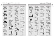
TAPE FOLDER AND MECHANICAL TAPE CUTTING DEVICEDOBLADOR DE CINTA Y CORTADOR MECANICO DE CINTARef. No.Ref. No.Part No.Parte No.Description Descripción Amt. Req.Cant. Req.1 - 49123456789101112131415161718192021222324252627282930313233343536373839404142434445464748*49G29901A50G29901A6093077G41041B2283793077C80640E93077D93077A93077B2254293993793077E22874G29497A87U21272127B2127C2127A966502103A-502103A-602103AA-502103AA-6099269J16142103AB39250J22585A2103ACG29486E995559955622585R80275995602284894995582170A2272496701995579955922570A402225622157E21882188C99271Tape Folder and Mechanical Tape CuttingDevice for 50 mm wide tapeTape Folder and Mechanical Tape CuttingDevice for 60 mm wide tapeTape Reel AssemblyCollarThumb ScrewSpringBushingTape Reel DiscTape Reel BracketTape GuideScrewScrewNutPlateScrewThroat Plate and Chaining Block AssemblyScrewChaining Block AssemblyGuide for Chaining BlockSpringChaining BlockRoll PinFolder Assembly for 50 mm wide tapeFolder Assembly for 60 mm wide tapeFolder for 50 mm wide tapeFolder for 60 mm wide tapeShoulder ScrewSpring WasherFolder BracketNutScrewShimTape ClipperKnife Actuating LeverBracket for knife shaftScrewLower KniferFinger GuardScrewScrewGuideUpper KnifeScrewSpringKnife ShaftSpringScrewStop ScrewScrew for guide 99558Front Cover (not shown)Support ArmSupport Arm for 2200L, LAScrewDoblador y cortador mecánico de cintaPara cintas de 50 mm de anchoDoblador y cortador mecánico de cintaPara cintas de 60 mm de anchoConjunto dispensador de cintaAbrazaderaTornillo de manoResorteBocinaDiscoSoporteGuíaTornilloTornilloTuercaPlanchaTornilloConjunto plancha de aguja y bloque form cadenetaTornilloConjunto bloque formación cadenetaGuía para el bloqueResorteFormador de cadenetaPasador redondoConj. Doblador para cintas de 50 mm de anchoConj. Doblador para cintas de 60 mm de anchoDoblador para cintas de 50 mm de anchoDoblador para cintas de 60 mm de anchoTornillo de encuentroArandela de resorteSujetador del dobladorTuercaTornilloPlaca conectoraConjunto cortador de cintaPalanca accionadora de la cuchillaSoporte del eje de la cuchillaTornilloCuchilla inferiorGuarda dedosTornilloTornilloGuíaCuchilla superiorTornilloResorteArbol de la cuchillaResorteTornilloTornillo topeTornillo para guía 99558Cubierta frontal (no se muestra)Brazo de SoporteBrazo de soporte para 2200L, LATornillo cilíndrico1111112112331312111111111111121111311141111112121111*Extra order and charge item.* Contra pedido, cargo adicional.27
BAG CLOSING MACHINE 2200AZ4015FAN AND 2200AAZ4015FAN FOR BAG CLOSING UNITSMAQUINAS CERRADORAS DE SACOS 2200AZ4015FAN Y 2200AAZ4015FAN PARA ESTACIONES COMPLETASRef. No.Ref. No.Part No.Parte No.Description Descripción Amt. Req.Cant. Req.12345678910111213*2280480265216121622121FAN2121FA96256995-5042165FAN88D228742124FAN999-311ScrewWasherBall BearingClamp PlateFlange AssemblyFlangeRetaining RingBall BearingPinionScrewScrewThroat Plate for cutter below(not shown)Cutter, pneumatically actuated, for Thread Chain(not shown)TornilloArandelaRodamientoPlacas sujetadorasConjunto del CojineteCojineteRetenedor 9x1Cojinete de bolasPiñónTornilloTornilloPlancha de aguja para cortador abajo (no semuestra en el dibujo)Cortador de cadeneta neumático (no semuestra en el dibujo)2212111112211* Extra send and charge item.* Contra pedido, cargo adicional.Only the parts found on Styles 2200AZ4015FAN and2200AAZ4015FAN are illustrated which are different from thoseof Styles 2200A and 2200AA.Solo se muestran las partes para estilos 2200AZ4015FANy 2200AAZFAN4015 y que son diferentes de los estilos2200 A y 2200AA.29
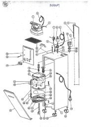
MOTOR ASSEMBLY PART NO. 29929A (220-240 V, 50/60 Hz) STYLES 2200A, AAProtection Class I, with ground wireCONJUNTO DEL MOTOR PARTE NO. 29929A (220-240 V, 50/60 Hz) ESTILOS 2200A, AAProtección Clase I, con cable tierraRef. No.Ref. No.Part No.Parte No.Description Descripción Amt. Req.Cant. Req.123456789101112131415161718192021222323A*2425262729929A955802129MM129VG90233B998-4162288992719566595257V998-20B998-20BA9558199654B955802265DA9551595182V2265999-2332265C95515997A502N997AE3D502N995-506A995-518A995-524995-523Motor AssemblyScrewMotor HousingPower PlateCable with PlugProtecting SleeveBracketScrewScrewNutThumb SwitchGasketScrewCable ClampScrewSprocket WheelScrewGrounding ScrewPinion with Bearing AssemblyToothed BeltSprocket WheelScrewBuilt-in MotorBuilt-in Motor, II 3 D T4 135° C,ATEX Directive 94/9/ECCooling FanCommutator BrushALWAYS ORDER IN PAIRSLock for Commutator BrushRadioshielding CapacitorConjunto del MotorTornilloCubierta del MotorPlaca con especificaciones eléctricasCable con enchufeManga protectora del cableSoporteTornilloTornilloTuercaBoton de arranqueEmpaquetaduraTornilloSujetador del cableTornilloPiñón mayorTornillo remacheTornillo tierraConjunto de Piñón con rodamientoCorrea dentadaPiñón mayorTornillo remacheMotor integradoMotor integrado, II 3 D T4 135° C,Directriz ATEX 94/9/EGVentilador para enfriamentoCarbonesSIEMPRE ORDENE EN PARESSeguro para los carbonesCondensador1311111122114121111111111221* Extra order and charge item. * Contra pedido, cargo adicional.31
MOTOR ASSEMBLY PART NO. 29929BC (110-125V, 50/60 Hz) STYLES 2200B, BAProtection Class I, with ground wire greenCONJUNTO DEL MOTOR PARTE NO. 29929BC (110-115V, 50/60 Hz) ESTILOS 2200B,BA Protección Clase I, con cable tierra verdeRef. No.Ref. No.Part No.Parte No.Description Descripción Amt. Req.Cant. Req.12345678910111213141516171819202122232425262729929BC955802129MM129VDE90233BA998-4162288992719566595257V998-20B998-20BA9558199654B955802265DA9551595182V2265999-2332265C95515997BC502995-506A995-518A995-524C55Motor AssemblyScrewMotor HousingPower PlateCableProtecting SleeveBracketScrewScrewNutThumb SwitchGasketScrewCable ClampScrewSprocket WheelScrewGrounding ScrewPinion with Bearing AssemblyToothed BeltSprocket WheelScrewBuilt-in MotorCooling FanCommutator BrushALWAYS ORDER IN PAIRSLock for Commutator BrushPlugConjunto del MotorTornilloCubierta del MotorPlaca con especificaciones eléctricasCableManga protectora del cableSoporteTornilloTornilloTuercaBoton de arranqueEmpaquetaduraTornilloSujetador del cableTornilloPiñón mayorTornillo remacheTornillo tierraConjunto de Piñón con rodamientoCorrea dentadaPiñón mayorTornillo remacheMotor integradoVentilador para enfriamentoCarbonesSIEMPRE ORDENE EN PARESSeguro para los carbonesEnchufe13111111221141211111111122133
MOTOR ASSEMBLY PART NO. 29929F (42 V, 50/60 Hz) STYLES 2200F, FAProtection Class III, safety extra-low voltageCONJUNTO DEL MOTOR PARTE NO. 29929F (42 V, 50/60 Hz) ESTILOS 2200F, FAProtección Clase III, bajo voltaje extra seguroRef. No.Ref. No.Part No.Parte No.Description Descripción Amt. Req.Cant. Req.12345678910111213141516171819202122232425262729929F955802129MM129VC90233F998-4162288992719566595257V998-20B998-20BA9558199654B955802265DA955152265B999-2332265C95515997F502995-506A995-518F995-524995-523998-266AMotor AssemblyScrewMotor HousingPower PlateCableProtecting SleeveBracketScrewScrewNutThumb SwitchGasketScrewCable ClampScrewSprocket WheelScrewPinion with Bearing AssemblyToothed BeltSprocket WheelScrewBuilt-in MotorCooling FanCommutator BrushALWAYS ORDER IN PAIRSLock for Commutator BrushRadioshielding CapacitorPlugConjunto del MotorTornilloCubierta del MotorPlaca con especificaciones eléctricasCableManga protectora del cableSoporteTornilloTornilloTuercaBoton de arranqueEmpaquetaduraTornilloSujetador del cableTornilloPiñón mayorTornillo remacheConjunto de Piñón con rodamientoCorrea dentadaPiñón mayorTornillo remacheMotor integradoVentilador para enfriamentoCarbonesSIEMPRE ORDENE EN PARESSeguro para los carbonesCondensadorEnchufe13111111221141211111111221135
MOTOR ASSEMBLY PART NO. 29929M (12 V DC) STYLES 2200M, MAProtection Class III, safety extra-low voltageCONJUNTO DEL MOTOR PARTE NO. 29929M (12 V DC) ESTILOS 2200M, MAProtección Clase III, bajo voltaje extra seguroRef. No.Ref. No.Part No.Parte No.DescriptionDescripciónAmt. Req.Cant. Req.12345678910111213141516171819202122232429929M955802129MYM129VH90233F998-4162288992719566595257V998-20B998-20BA9558199654B955802265DA955152265B999-2332265C95515997Y502995-506A995-518YAMotor AssemblyScrewMotor HousingPower PlateCableProtecting SleeveBracketScrewScrewNutThumb SwitchGasketScrewCable ClampScrewSprocket WheelScrewPinion with Bearing AssemblyToothed BeltSprocket WheelScrewBuilt-in MotorCooling FanCommutator BrushALWAYS ORDER IN PAIRSConjunto del MotorTornilloCubierta del MotorPlaca con especificaciones eléctricasCableManga protectora del cableSoporteTornilloTornilloTuercaBoton de arranqueEmpaquetaduraTornilloSujetador del cableTornilloPiñón mayorTornilloConjunto de Piñón con rodamientoCorrea dentadaPiñón mayorTornilloMotor integradoVentilador para enfriamentoCarbonesSIEMPRE ORDENE EN PARES13111111221141211111111237
MOTOR ASSEMBLY PART NO. 29929AS (220-240 V, 50/60 Hz) STYLES <strong>2200AS</strong>, AASProtection Class II, without ground wireCONJUNTO DEL MOTOR PARTE NO. 29929AS (220-240 V, 50/60 Hz) ESTILOS <strong>2200AS</strong>, AASProtección Clase II, sin cable tierraRef. No.Ref. No.Part No.Parte No.DescriptionDescripciónAmt. Req.Cant. Req.123456789101112131415161718192021222324252629929AS955802129MM129VF90233A998-4162288992719566595257V998-20B998-20BA9558199654B955802265DA955152265B999-2332265C95515997A502N995-506A995-518A995-524995-523Motor AssemblyScrewMotor HousingPower PlateCable with PlugProtecting SleeveBracketScrewScrewNutThumb SwitchGasketScrewCable ClampScrewSprocket WheelScrewPinion with Bearing AssemblyToothed BeltSprocket WheelScrewBuilt-in MotorCooling FanCommutator BrushALWAYS ORDER IN PAIRSLock for Commutator BrushRadioshielding CapacitorConjunto del MotorTornilloCubierta del MotorPlaca con especificaciones eléctricasCable con enchufeManga protectora del cableSoporteTornilloTornilloTuercaBoton de arranqueEmpaquetaduraTornilloSujetador del cableTornilloPiñón mayorTornillo remacheConjunto de Piñón con rodamientoCorrea dentadaPiñón mayorTornillo remacheMotor integradoVentilador para enfriamentoCarbonesSIEMPRE ORDENE EN PARESSeguro para los carbonesCondensador1311111122114121111111122139
MOTOR ASSEMBLY PART NO. 29929MB (24 V DC) STYLES 2200MB, MABProtection Class III, safety extra-low voltageCONJUNTO DEL MOTOR PARTE NO. 29929MB (24 V DC) ESTILOS 2200MB, MABProtección Clase III, bajo voltaje extra seguroRef. No.Ref. No.Part No.Parte No.DescriptionDescripciónAmt. Req.Cant. Req.1234567891011121314151617181920212223242526272829929MB955802129MM129VJ90233P998-4162288992719566595257V998-20B998-20BA9558199654B955802265DA9551590195C2265B999-2332265C95515997YY502995-506A995-518YY995-5249019590195BMotor AssemblyScrewMotor HousingPower PlateCableProtecting SleeveBracketScrewScrewNutThumb SwitchGasketScrewCable ClampScrewSprocket WheelScrewPlugPinion with Bearing AssemblyToothed BeltSprocket WheelScrewBuilt-in MotorCooling FanCommutator BrushALWAYS ORDER IN PAIRSLock for Commutator BrushBattery BeltBattery ChargerConjunto del MotorTornilloCubierta del MotorPlaca con especificaciones eléctricasCableManga protectora del cableSoporteTornilloTornilloTuercaBoton de arranqueEmpaquetaduraTornilloSujetador del cableTornilloPiñón mayorTornillo remacheEnchufeConjunto de Piñón con rodamientoCorrea dentadaPiñón mayorTornillo remacheMotor integradoVentilador para enfriamentoCarbonesSIEMPRE ORDENE EN PARESSeguro para los carbonesCorrea para bateriasCargador de baterias131111112211412111111111221127 2841
ACCESSORIESACCESORIOSRef. No.Ref. No.Part No.Parte No.Description Descripción Amt. Req.Cant. Req.1*Z1-124-250BLZ1-124-250GEZ1-124-250GNZ1-124-250RTZ1-124-250WSZ1-204-250WSZ2-124-200WSThread Cone, Viscose, blue, 200 gThread Cone, Viscose, yellow, 200 gThread Cone, Viscose, green, 200 gThread Cone, Viscose, red, 200 gThread Cone, Viscose, white, 200 gThread Cone, Polyester, white, 200 gThread Cone, Polypropylene, white, 200 gCono de hilo, Viscosa, azul, 200 gCono de hilo, Viscosa, amarillo, 200 gCono de hilo, Viscosa, verde, 200 gCono de hilo, Viscosa, rojo, 200 gCono de hilo, Viscosa, blanco, 200 gCono de hilo, Poliester, blanco, 200 gCono de hilo, Polipropileno, blanco, 200 g1 or / o 21 or / o 21 or / o 21 or / o 21 or / o 21 or / o 21 or / o 22*DF1-065-150Filler Cord, grey, 150 gCordón de relleno, gris, 150 g13*95601Hexagon Socket Head Wrench, Size 4 mmLlave hexagonal (Allen) , 4 mm14*95606Hexagon Socket Head Wrench, Size 2.5 mmLlave hexagonal (Allen), 2,5 mm15*21225-4/4.4Looper Gauge for Two Thread Double Locked StitchCalibrador de looper para costura decadeneta doble15A*21225-9/64Looper Gauge for Single Thread ChainstitchCalibrador de looper para costura decadeneta sencilla16*9854G-Div.Needle (see also paragraph "NEEDLES")Aguja (Ver también parágrafo "AGUJAS")1795626Screwdriver for Recessed-head Screw,Size 2Destornillador de estrias, tamaño 218*21202Screwdriver, 0.8 x 5.5 x 245 mm Length over allDestornillador plano, 0,8 x 5,5 x 245 mm1921201Screwdriver, 0.5 x 3.5 x 195 mm Length over allThreading HookDestornillador plano, 0,5 x 3,5 x 195 mmEnhebrador110*11*J118B116Single ended open Jaw Wrench,Size 7.2 mmOil, 0.5 l ContainerLlave sencilla, 7,2 mmAceite, envase de medio litro (0,5 l)1112*G28604LOil, 5.0 l ContainerAceite, envase de 5 litros (5,0 l)1G28604L5Oil CanAceitera113G43294BPair of TweezersPinza114118GGrind FileLija de Carbon115*16*999-117998A61ASingle-phase Safety Transformer with Handle,splashproof. Primary 220 V, secondary 42 V, 50/60 Hz, power 250 VA.For Styles 2200F and 2200FA.Transformador, 1 fase, con mangosujetador, a prueba de salpicaduras deagua. Primario 220 V, secundario 42 V,50/60 Hz, 250 VA.Para máquinas estilos 2200F y 2200FA.11* Extra order and charge item.* Contra pedido, cargo adicional.43
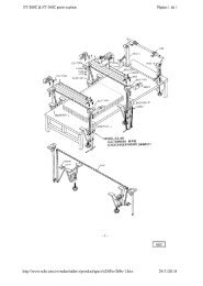
PEDESTAL FOR STYLES 2200A, B, AS, AA, BA, AAS*PEDESTAL PARA ESTILOS 2200A, B, AS, AA, BA, AAS*Ref. No.Ref. No.Part No.ParteNo.Description Descripción Amt. Req.Cant.Req.1*H1400FPedestal and Foot Switch AssemblyConjunto Interruptor de pie para pedestal122288BLeaf Spring for Thumb SwitchBallesta para el boton de arranque13A9355Machine Support AssemblyConjunto de soporte de la máquina141460TClamp ScrewTornillo sujetador151460PMachine SupportSoporte de la máquina161460XRubber PadConjinete de goma4796877PinPasador1281460RClampSujetador1996854Center Groved Dowel PinPasador fijo central11095800StudPerno1111025UWasherArandela1121460WClamp NutTuerca de sujeción1131401DBaseBase de la columna11495204Set ScrewTornillo de sujeción11595215Spot ScrewTornillo de punto fijo116G105BScrew with Nut and WasherTornillo con tuerca y arandela31796902WasherArandela11895251NutTuerca119998-46Foot SwitchInterruptor de pié1201403BColumn 535 mm (approx. 21") longColumna 535 mm largo121*1403B1300Column 1300 mm (approx. 51") longColumna 1300 mm largo122*2103EBag Feed-in Guide and Finger Guard withlonger guides, preferable for styles usedstationary with pedestal.Guía para alimentación de sacos y protector dededos con guías mas largas, recomendado paramáquinas en estaciones de ensacado conpedestales.12322585BScrewTornillo2242105ACWasher PlatePlatina1Tables for pedestal see following pages.Mesas para pedestal, ver páginas siguientes* Extra order and charge item.* Contra pedido, cargo adicional.45
TABLES FOR PEDESTAL MOUNTED STYLES*MESAS PARA ESTILOS MONTADOS EN PEDESTAL*Ref. No.Ref. No.1*23456Part No.Parte No.A9847BG61371KB90561KA9847C999-135D999-136DDescription Descripción Amt. Req.Cant. Req.Small movable table, lenght 700 mm(279/16") width 550 mm (215/8"), height 760 mm(30")Table BoardWood ScrewFrame, movableRollerGuide Roller, lockableMesa pequeña, movible, Largo 700 mm,Ancho 550 mm, Alto 760 mmTabla de la mesaTornillo para maderaMarco, removibleRuedasRuedas con guias y frenos incorporados1141227*90709PSMovable Table with Roller Type Conveyor, length1060 mm (413/4"), width 550 mm (215/8"), heightajdustable from 860 to 970 mm (337/8"- 38").Mesa movible con rodillos transportadores, Largo1060 mm, Ancho 550 mm, Alto ajustable de 860 a970 mm.18910111213141516G21371WY190710A9071190561G90561G96901Z95322Z96121Z999-135A999-136Table BoardMagnetRoller Type ConveyorWood Screw for Roller Type ConveyorWood Screw for Table TopWasherHex. Head ScrewLock WasherRollerGuide Roller, lockableTabla de la mesa1Magneto (iman)1Rodillos transportadores1Tornillos para madera para rodillos transportadores8Tornillos para madera para mesa tope4Arandela4Tornillo cabeza hexagonal8Arandela de seguridad4Ruedas2Ruedas con guias y frenos incorporados 217*18192021222324252690709PRG21371WY190710A9071190561G90561G96901Z95322Z96121Z90709PB90709PATable with Roller Type Conveyor, length 1060mm (413/4"), width 550 mm (215/8"), heightadjustable from 725 to 835 mm (28 1/2" - 33 7/8").Table BoardMagnetRoller Type ConveyorWood Screw for Roller Type ConveyorWood Screw for Table TopWasherHex. Head ScrewLock WasherVibration Damper, adjustableVibration DamperMesa con rodillos transportadores, Largo 1060 mm,Ancho 550 mm, Alto ajustable de 725 a 835 mm.Tabla de la mesaMagneto (iman)Rodillos transportadoresTornillos madera para rodillos transportadoresTornillos para madera para mesa topeArandelaTornillo cabeza hexagonalArandela de seguridadRegulador de vibración, ajustableRegulador de vibración1111844841327*A9847BSSmall movable table, same as A9847B, but withsocket for sewing head, support for foot switch andmain switch.Mesa pequeña, movible,igual a A9847B, pero con 1cavidad para colocar máquina de coser, con interruptorde pie y boton de arranque.28293031998-94B998-348-1A9847D998-246FSocketFuse 1 ASupport for foot switch (see alsopedestal and foot switch assemblyH1400F)Main SwitchEnchufeFusible 1 ASoporte para interruptor de pie (ver tambienPedestal con interruptor H1400F)Interruptor principal111132*3390709PSA90709PQ2Movable Table with Roller Type Conveyor, sameas 90709PS but with socket for sewing head,support for foot switch and main switch (notshown)Support for foot switch (not shown)Mesa movible con rodillos transportadores, igual a la 190709PS,pero con cavidad para colocar máquina decoser, con interruptor de pie y boton de arranque.(no se muestra en el dibujo)Soporte para interruptor de pie (no se muestra en el 1dibujo)* Extra order and charge item. 47 * Contra pedido, cargo extra.
TOP LOCK SPRING BALANCER FOR STYLE 2200A, B, F, AA, AS, BA, FA, AASPOLIPASTO PARA MODELOS 2200A, B, F, AA, AS, BA, FA, AASThe top lock spring balancer part No. 90191M isrecommended for effortless operation of themachines. It keepts the suspended machinealways handy and save.IMPORTANT! Before putting the balancer intoservice read the instructions and observe thesafety rules of the supplier!Polipasto, parte No. 90191Mse recomienda para unaoperación mas liviana de las máquinas. Siempremantiene la máquina suspendida , a la mano y a salvode accidentes.IMPORTANTE! Por favor lea las instrucciones deseguridad y las recomendaciones del fabricante, antesde poner el equipo en uso.!Ref. No.Ref. No.1*2345Part No.Parte No.90191M90191M1218899271Description Descripción Amt. Req.Cant. Req.Top Lock Spring Balancer AssemblyBalancerBrackerScrew for BracketInstructions (not shown)Conjunto del polipastotBalanceadorSoporteTornillo del soportelInstrucciones (no se muestran)* Extra order and charge item. * Contra pedido, cargo extra.1111148
THREAD STAND PART NO. 93065CPORTA CONOS PARTE NO. 93065CRef. No.Ref. No.Part No.Parte Nr.Description Descripción Amt. Req.Cant. Req.1234567891011121393065C93065CB93065CD93065CA96902952912289B9927093065CC93B955802158F2158GThread Stand for Filler Cord completeCone SupportRodThread EyeletWasherNutSpool PinThumb ScrewBracketScrewScrewThread EyeletThread Eyelet for Filler CordConjunto del Porta ConosSoporte de los conosVarillaPasa hilosArandelaTuercaPorta conoTornillo de manoSoporteTornilloTornilloPasa hilosPasa hilos para cordeles111144331311151
NUMERICAL INDEX OF PARTSINDICE NUMERICO DE PARTESPart No.Parte No.PageSeite1025U ... 45109 ... 21116 ... 43118G ... 4312934A ... 21, 231401D ... 451403B ... 451403B1300 ... 451460P ... 451460R ... 451460T ... 451460W ... 451460X ... 452101 ... 252103A-50 ... 272103A-60 ... 272103AA-50 ... 272103AA-60 ... 272103AB ... 272103AC ... 25, 272103E ... 452105 ... 232105AC ... 452108 ... 232108B ... 232115 ... 232120 ... 2121201 ... 4321202 ... 432121FA ... 292121FAN ... 292122 ... 2521225-4/4,4 ... 4321225-9/64 ... 432124 ... 252124FAN ... 292125 ... 232126 ... 212127 ... 25, 272127A ... 25, 272127B ... 25, 272127C ... 25, 272129B ... 19, 252129M ... 31, 33, 35, 39, 412129MY ... 372130 ... 252131 ... 232132 ... 232133 ... 232134A ... 232135N ... 232135R ... 232136 ... 232139N ... 232140N ... 19, 232141 ... 252142 ... 232143 ... 212144 ... 232145 ... 25Part No.Parte No.2145A ... 232146 ... 212148 ... 252149 ... 252150 ... 252151 ... 232152 ... 232152B ... 232153 ... 232154 ... 252155 ... 252156 ... 232157 ... 252157E ... 272158A ... 212158B ... 232158C ... 212158D ... 212158E ... 232158F ... 512158G ... 512159A ... 212160N ... 212161 ... 292162 ... 292163 ... 212165A ... 19, 232165C0.5 ... 19, 232165D0.1 ... 19, 232165D0.2 ... 19, 232165D0.3 ... 19, 232165D0.5 ... 19, 232165D1.0 ... 19, 232165FAN ... 292166A ... 212167A ... 212168A ... 212169A ... 212170 ... 252170A ... 272171 ... 252172C ... 252173A ... 232175A ... 212176B ... 212176D ... 212177 ... 232178 ... 212179 ... 212180 ... 212182 ... 252182A ... 252182B ... 252182C ... 252183 ... 252186 ... 212188 ... 27, 482188C ... 272189C ... 212189H ... 2152PagePáginaPart No.Parte No.PagePágina2190 ... 192191 ... 19, 232192 ... 192193 ... 19, 21, 232193A ... 192194 ... 19, 232195N ... 19, 232196A ... 212196B ... 212203E ... 2522528 ... 21, 2522542 ... 25, 2722560B ... 2322561 ... 2522562 ... 2722570A ... 2722575 ... 2322585 ... 2522585A ... 21, 25, 2722585B ... 21, 25, 4522585R ... 2722596 ... 232265 ... 31, 332265B ... 35, 37, 39, 412265C ... 31, 33, 35, 37, 39, 412265DA ... 31, 33, 35, 37, 39, 4122724 ... 2722764 ... 2522764A ... 2322768 ... 2322804 ... 2922837 ... 2722848 ... 2722874 ... 27, 292288 ... 31, 33, 35, 37, 39, 412288B ... 452289B ... 21, 5128 ... 23, 2528C ... 21, 2329929A ... 3129929AS ... 3929929BC ... 3329929F ... 3529929M ... 3729929MB ... 4139250J ... 2739350J ... 23402 ... 2741071G ... 21, 2351192G ... 2151225W ... 21, 2351292A ... 2151292C ... 2151292F1 ... 2151292F8 ... 2151758 ... 21538 ... 2573 ... 2573C ... 2376099D ... 19
NUMERICAL INDEX OF PARTSINDICE NUMERICO DE PARTESPart No.Parte No.PagePáginaPart No.Parte No.PagePáginaPart No.Parte No.PagePágina77K ... 2579 ... 2180175 ... 21, 2380265 ... 2980275 ... 2780640E ... 2787A ... 21, 2587U ... 21, 25, 2788 ... 2588B ... 2388D ... 2990191M ... 4890191M1 ... 4890195 ... 4190195B ... 4190195C ... 4190233A ... 39, 4190233B ... 3190233BA ... 3390233F ... 35, 3790561G ... 4790561K ... 47907 ... 2190709PA ... 4790709PB ... 4790709PQ2 ... 4790709PR ... 4790709PS ... 4790709PSA ... 4790710A ... 4790711 ... 4793 ... 21, 2793065C ... 5193065CA ... 5193065CB ... 5193065CC ... 5193065CD ... 5193077 ... 2793077A ... 2793077B ... 2793077C ... 2793077D ... 2793077E ... 2793640 ... 2193B ... 21, 5194 ... 2795182V ... 31, 3395204 ... 4595215 ... 4595251 ... 4595257 ... 31, 33, 35, 37, 39, 4195291 ... 5195322Z ... 4795515 ... 31, 33, 35, 37, 39, 4195580 ... 21, 31, 33, 35, 37, 39, 41, 5195581 ... 31, 33, 35, 37, 39, 4195601 ... 4395606 ... 4395626 ... 4395665 ... 31, 33, 35, 37, 39, 4195800 ... 4595954 ... 2196121Z ... 4796256 ... 25, 2996501 ... 2396502 ... 2396511 ... 1996523 ... 1996602 ... 2396603 ... 2396650 ... 25, 2796663 ... 2196701 ... 2796854 ... 4596877 ... 4596901Z ... 4796902 ... 45, 519854G-Div. ... 4399266 ... 1999266A ... 1999267 ... 2399268 ... 2199269 ... 25, 2799270 ... 21, 5199271 ... 27, 31, 33, 35, 37, 39, 41, 4899277 ... 239937 ... 2799373 ... 25995-504 ... 29995-506A ... 31, 33, 35, 37, 39, 41995-518A ... 31, 33, 39995-518F ... 35995-518YA ... 37995-518YY ... 41995-523 ... 31, 35, 39995-524 ... 31, 33, 35, 39, 4199521 ... 2399555 ... 2799556 ... 2799557 ... 2799558 ... 2799559 ... 2799560 ... 2799654B ... 31, 33, 35, 37, 39, 41997A502N ... 31, 39997AE3D502N ... 31997BC502 ... 33997F502 ... 35997Y502 ... 37997YY502 ... 41998-20B ... 31, 33, 35, 37, 39, 41998-20BA ... 31, 33, 35, 37, 39, 41998-246F ... 47998-266A ... 35998-348-1 ... 47998-416 ... 31, 33, 35, 37, 39, 41998-46 ... 45998-94B ... 47998A61A ... 43999-104A ... 1953999-117 ... 43999-135A ... 47999-135D ... 47999-136 ... 47999-136D ... 47999-233 ... 31, 33, 35, 37, 39, 41999-311 ... 29A9355 ... 45A9847B ... 47A9847BS ... 47A9847C ... 47A9847D ... 47B660-210 ... 23C55 ... 33G10349 ... 25G105B ... 45G21371WY1 ... 47G22585A ... 21G28604L ... 43G28604L5 ... 43G29486E ... 27G29490 ... 25G29492 ... 23G29493B ... 21G29496 ... 21G29497 ... 25G29497A ... 27G29901A50 ... 27G29901A60 ... 27G41041B ... 27G41046G ... 19G43266 ... 21G43294B ... 43G61371KB ... 47G660-210 ... 23H1400F ... 45HA61D ... 23J118B ... 43J1614 ... 25, 27M129VC ... 35M129VDE ... 33M129VF ... 39, 41M129VG ... 31M129VH ... 37
NOTESNOTAS54
NOTESNOTAS55