Barriera a catena per l'accesso carrabile fino a 16 m ... - Antriebe 24
Barriera a catena per l'accesso carrabile fino a 16 m ... - Antriebe 24
Barriera a catena per l'accesso carrabile fino a 16 m ... - Antriebe 24

Create successful ePaper yourself
Turn your PDF publications into a flip-book with our unique Google optimized e-Paper software.
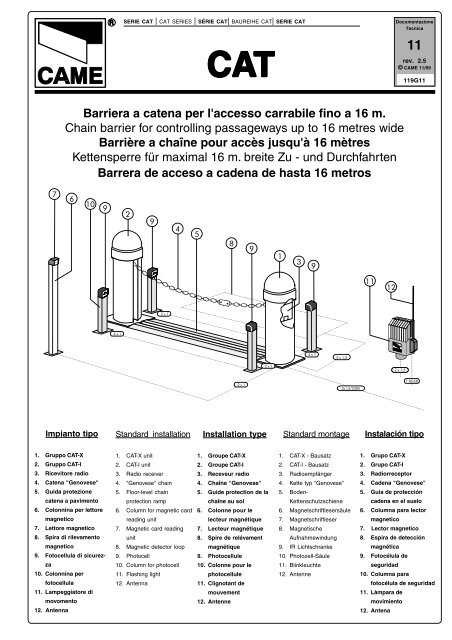
FRANÇAISCARACTÉRISTIQUES GÉNÉRALÉSDescription:- Barrière a chaîne pour accès jusqu'à <strong>16</strong> mètres- Il a été entièrement concu et construit par la Société CAME,conformément aux normes de sécurité en vigueur (NFP 25-362) avec degré de protection IP 54.- Il est garanti 12 mois sauf en cas d'altérations.Composition:CAT - XPilier galvanisé verní avec finition RAL 7035, avec motoréducteuren 230V a. c. et armoire de commande incorporée.CAT - IPilier galvanisé verní avec finition RAL 7035 avec contrepoidset élément d'accrocage pour chaîne.Limites d'utilisation:- 8 mètres max., avec chaîne "genovese" de 9 mm. CAT 5.- <strong>16</strong> mètres max., avec chaîne "genovese" de 5 mm. CAT 15.Accessoires:CAT 5Chaîne type "genovese" de 9 mm., galvanisé verní avecfinition RAL 2004 (7,5 m.).CAT 15Chaîne type "genovese" de 5 mm., galvanisé verní avecfinition RAL 2004 (15,5 m.).CAR 2Guide de protection de la chaîne au sol (piéces de 2 m.).CAR 4Guide de protection de la chaîne enterré (piéces de 2 m.).N.B.: des vernis thermodurcissables à base de résinespolyesters sont utilisés pour toutes les pièces vernies.Attention ! Vérifiez que l’appareillage de commande, de sécurité et les accessoires sont des produits originaux CAME afin de garantirl’installation et d’en faciliter le montage et l’entretien.DEUTSCHALLGEMEINE MERKMALEBeschreibung:- Kettens<strong>per</strong>re für maximal <strong>16</strong> m. breite Zu - und Durchfahrten- Vollkommen von der CAME S.p.A. den geltendenSicherheitsnormen (UNI 8612) entsprechend entwickelt undhergestellt. Schutzklasse IP 54.- Garantie: 12 Monate, vorbehaltlich unsachgemäßerHandhabung und Montage.Ausrüstung:CAT - XVerzinkter und lackiert (RAL 7035) Pfeiler mit 230VWechselstrom Motor und Eingebaute Steuereinheit.CAT - IVerzinkter und lackiert (RAL 7035) Pfeiler mit Gegengewicht undKettenkupplung.Einsatzgrenze:- Bei Ausrüstung mit 9 mm. Kette typ "genovese", erlaubt dasCAT-System den Antrieb von bis zu 8 m. breiten Durchgängen;- Bei 5 mm. Kette typ "genovese" bis zu <strong>16</strong> m. breitenDurchgängen.Zubehör:CAT 5Kette typ "genovese", 9 mm., verzinkt und Lackierter (RAL2004 - Länge 7,5 m.).CAT 15Kette typ "genovese", 5 mm., verzinkt und Lackierter (RAL2004 - Länge 15,5 m.).CAR 2Verzinkter Boden-Kettenschultzschiene (2 m. Stuck).CAR 4Verzinkter Bodenlaufschiene für die Kette je (2 m. Stuck).Hinweis: für alle lackierten Teile sind wärmehärtendePolyesterharzlacke verwendet worden.Achtung! Wir empfehlen original CAME-Schalt- und -Sicherheitsvorrichtungen mit entsprechendem Zubehör zu montieren, um dieeinwandfreie Montage und die problemlose Wartung der Anlage zu gewährleisten.- 3 -
ESPAÑOLCARACTERÍSTICAS GENERALESDescripción:- Barrera de acceso a cadena de hasta <strong>16</strong> metros.- Diseñado y fabricado enteramente por CAME S.p.A., cumplecon las normas de seguridad vigentes UNI 8612, con grado deprotección IP54.- Garantizado 12 meses, salvo manipulaciones.Composción:CAT - XPilar con motorreductor a 230V a.c. y cuadro de mandosincorporado.CAT - IPilar de complemento con gancho, cadena y dispositivo dedesbloqueo.Limites de empleo:- 8 m. con el uso de la cadena "genovese" de 9 mm.;- <strong>16</strong> m. con el uso de la cadena "genovese" de 5 mm.;Accesorios:CAT 5Cadena de tipo "genovese" de 9 mm., cincada con acabadopor barniz (pedazos de m. 7,5).CAT 15Cadena de tipo "genovese" de 5 mm., cincada con acabadopor barniz (pedazos de m. 15,5).CAR 2Guia de protección de la cedena en el suelo.CAR 4Guia protectora subterránea para cadena (trozos de 2 m.).Nota: para todas las partes pintadas se utilizan pinturastermoendurecedoras a base de resinas poliésteres.Atención! Comprobar que los equipos de mando, de seguridad y los acesorios sean originales CAME; lo cual garantiza y facilita el usoy el mantenimiento del aparato.Caratteristiche tecniche - Technical features - Caractéristiques technique - Technische Daten - Descripción técnicaTIPOTYPETYPETYPTIPOPESOWEIGHTPOIDSGEWICHTPESOALIMENTAZIONEPOWER SUPPLYALIMENTATIONSTROMVERSORGUNGALIMENTACIÓNASSORBIMENTOCURRENT DRAWABSORPTIONSTROMAUFNAHMEABSORBENCIAPOTENZAMOTOREMOTOR POWERPUISSANCEMOTEURWIRKLEISTUNGMOTORPOTENCIAMOTORINTERMIT.LAVORODUTY CYCLEINTERM. TRAVAILEINSCHALTDAUERINTERM. TRABAJOFORZA DITRAZIONETRACTIVE FORCEFORCE DETRACTIONANTRIEBSKRAFTFUERZA DETRACCIÓNCONDENSATORECAPACITORCONDENSATEURKONDENSATORCONDENSADORTEMPO DIMANOVRAMANOEUVRE TIMETEMPS DEMANOEUVRESCHALTZEITTIEMPO DEMANIOBRACAT - X 43 230V a.c. 2,7 A max. 200 W 30 % 50 KG 20 µF 11 sMisure di ingombro - External dimensions - Mesures d'encombrement - Außenabmessungen - Dimensiones máximas520780280- 4 -
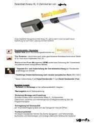
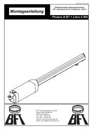
ACAT - XCAT - IITALIANODescrizione tecnicaCAT XBCDEFNILMOPA - Vite fissaggio calotta.B - Calotta asportabile in acciaio zincato con finitura di verni -ciatura.C - Fianchi asportabili.D - Quadro comando incorporato.E - Telaio in acciaio zincato con finitura di verniciatura.F - Motoriduttore <strong>24</strong>V d.c. in esecuzione corazzata con calottain alluminio pressofuso e protettore termicoincorporato.G - Piastra di fissaggio a pavimento in acciaio zincato.H - Zanche di ancoraggio più bulloneria in acciaio zincato.I - Puleggia in nylon <strong>per</strong> scorrimento <strong>catena</strong>.L - Catena di servizio e morsetto di aggancio in acciaio zincato.M - Puleggia avvolgente in nylon.N - Sblocco a chiave.GHCAT I - Pilastro con contrappesoO - Contrappeso di bilanciamento.P - Elemento fisso <strong>catena</strong>.ABCDEFGHILENGLISHCAT X- Cover fixer screw.- Removable casing in galvanised steel with painted finish.- Removable carter.- Built-in control panel.- Galvanised steel frame with painted finish.- <strong>24</strong>V d.c. gear motor armoured motor with cover in diecast aluminium and built in thermal circuit-breaker.- Floor-level anchor plate in galvanised steel.- Anchor bolts in galvanised steel nuts.- Nylon pulley for chain.- Service chain and clasp in galvanised steel.M - Nylon guide pulley.N - Key-o<strong>per</strong>ated release.Technical descriptionFRANÇAISDescription techniqueCAT XA - Vis de fixation calotte.B - Calotte amovible en acier zinguè avec vernissage de finition.C - Carter amovibles.D - Armoire de commande incorporée.E - Coffre en acier zingué avec vernissage de finition.F - Motoréducteur en <strong>24</strong>V d.c., protégé par une calotte enaluminium moulé sous pression, protecteur thermique incorporé.G - Plaque de fixation au sol en acier zingué.H - Agrafes de fixation avec boulonnerie en acier zingué.I - Poulie en nylon pour coulissement chaîne,L - Chaîne de service et crochet en acier zingué.M - Poulie d'enroulement en nylon.N - Déblocage à clé.CAT I - Post with counterweightO - Balancing counterweight.P - Fixed chain element.OPCAT I - Pilier avec contrepoids- Contrepoids d'equilibrage.- Morceau de chaîne fixe.DEUTSCHTechnische BeschreibungCAT XESPAÑOLDéscripcion técnicaCAT XABCDEFGHIL- Schraube für die Befestigung der Kappe.- Abnehmbare Pfeilerkappe aus verzinktem Stahl mit Lackberzug.- Entfernbare Seitenteile.- Eingebaute Steuereinheit.- Gestell aus verzinktem Stahl mit Lacküberzug.- <strong>24</strong>V-Gleichstrom Getriebemotor- Bodenfestigungsplatte aud verzinktem Stahl.- Fundamentanker mit verzinkten Stahlschrauben.- Kettenführungsrolle aus nylon.- Bedienungskette und kettenverbindungsglied aus verzinktem Stahl.M - Kettenaufrollscheibe aus Nylon.N - Schlüsselentriegelung.ABCDEFGHIL- Tornillo sujeción casquette.- Casquete retirable de acero cincado con acabado por barniz.- Lados extirpables.- Cuadro de mandos incorporado.- Estructura metálica en forma de pilar con acabado por barniz.- Motorreductor a <strong>24</strong>V d.c. en instalación blindada con casquetede aluminio fundido y protector termico incorporado.- Placa de sujeción en el suelo de acero cincado.- Grapas de sujeción con tornillos de acero cincado.- Polea para el deslizamiento de la cadena de nylon.- Cadena de servicio y gancho de acero cincado.M - Polea de envolver de nylon.N - Desbloqueo con llave.OPCAT I - Pfeiler mit Gegenweicht- Ausgleichsgewicht.- Festsehender Kettenteil.OPCAT I - Poste con contrapeso- Contrapeso de equilibrado.- Elemento fijo cadena.- 5 -
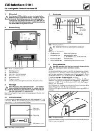
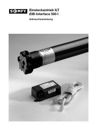
Preparazione - Before Installing... - Avant d'installer l'automatisme... - Vor den installation überprüfen...Antes de instalar el automatismo...Piastra di fissaggioFixing platePlaque de fixationGleitachsePlaca de fijaciónLuce netta - Opening space - Espace net - Passage utile - Abstand - Luz netaPiazzola in cementoConcrete basePlate-forme en cimentPlattenachsePlataforma de cemento 280Cavi elettriciElectrical cablesCâbles électriquesElektrische kabelCables eléctricos40280230Guida di protezione <strong>catena</strong> a pavimento CAR 2CAR 2 floor-level chain protection rampGuide de protection de la chaîne au sol CAR 2CAR 2 Boden-KettenschutzschieneGuia de protección de la cedena en el suelo CAR 2ZancheAnchor staysAgrafesVerankerungBarras de hierrode fijacion280230Descrizione di montaggioAssemblyDescription de montageMontageanweisungDescripción del montajeIl montaggio è estremamentesemplificato dagliaccorgimenti tecnicipropri del gruppo.-Predisporre, dimensionandolain base allemisure del gruppo, unapiazzola in cementocon annegate le piastredi fissaggio e relativezanche.- Le piastre di fissaggiodovranno essere <strong>per</strong>fettamentein bolla, pulitee con il filetto delleviti completamente insu<strong>per</strong>ficie.- Dal centro della piastradi fissaggio relativaa CAT-X dovrannoemergere i cavi <strong>per</strong> ilcollegamento elettrico.- E’ consigliata l’applicazionedella guida diprotezione <strong>catena</strong> apavimento CAR 2 o laguida di protezioneinterrata CAR 4.- Effettuata la posadelle piastre di fissaggioe della guida a pavimento,si procedaall’installazione delgruppo.The simple technical designof this systemmakes it extremely easyto assemble.- Prepare a concretebase of a width which issuitable for the system tobe installed. The metalanchor brackets shouldbe embedded in the concretein the correct positions.- The anchor plates mustbe <strong>per</strong>fectly clean andlevel, and the screwthreads must be completelyexposed on thesurface.- The power cablesshould be passedthrough the hole in thecentre of the CAT-X anchorplate.- It is good practice to installthe CAR 2 pavement-mountedchain protectionguide or the CAR4 underground chain protectionguide.- After installing the anchorplates andfloor-level chain protectionramp, the pillarsthemselves can be installed.Le montage estextrêmement simpliflépar les astucestechniques propres augroupe.- Préparer, en tenantcomptedesdimensions du groupe,une base en ciment eny noyant les plaqes defixation qui <strong>per</strong>mettrontla fixation du groupe.- Les plaquesd’ancrage devront êtreparfaitement de niveau,propres et avec le filetdes vis complètementen surface.- Les câbles devrontsortir de la base pour lebranchementélectrique.- Il est conseilléd’appliquer la glissièrede protection chaîne ausol CAR 2 ou laglissière de protectionenterrée CAR 4.- Après avoir effectué lapause au sol desattaches et de la guide,on procède àl'installation du groupe.Die Montage derElemente ist dank dertechnisch in allenEinzelheiten durchdachtenBauweisehochst einfach.- Die Befestigungsplattenmüssen <strong>per</strong>fektwaagerecht ausgerichtetund völlig sauber sein.Die Ankerschraubengewindesollten ganz ausdenPlattenherausragen.- Die BodenbefestigunsplattemuB eben, sauberund livelliert sein; dasGewinde der FundamentanVerschraubenmuBvollLommen aus demBoden ragen und mittigzur Auflageflache derElemente liegen.- Zum Schutz der Ketteempfiehlt sich, dieBodenlaufschiene CAR2 oder die erdverlegteSchutzschiene CAR 4 zuverwenden.- Nach Einbau derFundamentanker undderBoden-Kettenschuizschienekonnen diePfeilerele-mentemontiert werden.El montaje resulta muysimple por losdispositivos técnicosproprios del grupo.- Predisponer, con ladimensiones enfunción de las medidasdel grupo, unaplataforma de cementoinsertando los placasde sujeción queconsentirán fijar elgrupo.- Las placas de fijacióndeberán estar<strong>per</strong>fectamenteniveladas, limpias ycon la rosca de lostornillos totalmente ensu<strong>per</strong>ficie.- De dichia basedeberán sobresalir loscables para la conexioneléctrica.- Se aconseja laaplicación de la guía deprotección de cadenaen el suelo CAR 2 o laguía de protecciónsubterránea CAR 4.- Una vez colocados losganchos y la guia en elsuelo, se empieza ainstalar el grupo.- 6 -
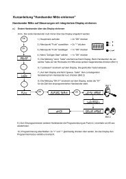
Posa del gruppo - Unit installation - Installation du groupe - Aufstellung des aggregats - Colocación del grupoMisura <strong>catena</strong>= luce netta - 500 mm.Chain size= opening space - 500mm.Dimension de la chaîne= espace net moins 500 mm.Kettenlange netto= Abstand 500 mm.Medida cadena= luz neta menos 500 mm.Sblocco <strong>catena</strong>Chain releaseDéblocage de la chaîneKettenentriegelungDesbloqueo cadenaCAT X1 ) Allentare le viti di fissaggioe togliere la calotta.2) Togliere i fianchi.3) Procedere alla posae al fissaggio del gruppo.4) Calcolata l’esatta misura(la misura esattadella <strong>catena</strong> da utilizzareè data dalla misuradella luce netta diminuitadi 500 mm.), tagliarela parte eccedente.5) Fissare un capo della<strong>catena</strong> di sbarramentoalla <strong>catena</strong> di serviziocon l’ausilio dell’appositomorsetto.6) Sempre con il gruppoin posizione a<strong>per</strong>ta,fissare l’altra estremitàdella <strong>catena</strong> ( servendosidello sblocco <strong>catena</strong>)all’elemento <strong>catena</strong>fisso su CAT I.7) Eseguire i collegamentielettrici sullamorsettiera quadro comando.CAT X1 ) Loosen the fixingscrews and remove thecasing.2) Remove the sides.3) Place the unit on theanchor plate and tightenthe anchor bolts.4) The exact length ofchain required is calculatedby subtracting 500mm. from the net distancebetween the pillars.Cut off the excess chain.5) Attach one end of thebarrier chain to the couplingfitted to the servicechain.6) With the unit still in theopen position, attach theother end of the chain(use the chain release) tothe fixed chain mount onCAT 1.7) Connect the powercables to the terminalboard on the controlpanel.CAT X1 ) Dévisser les vis defixation et retirer lacalotte.2) Retirer les panneauxlatéraux.3) Procedér à la pose eta la fixation du groupe.4) Aprés avoir calculéla dimension exacte (lamesure exacte de lachaîne à utiliser estdonnée par la mesurede l'espace net moins500 mm.) on coupel'xcédent.5) Fixer un extrémité dela chaîne de fermetureà la chaîne de serviceà l'aide de la borneappropriée.6) Toujours avec legroupe en positionouverte, fixer l’autreextrémité de la chaîne(en utilisant ledispositif de déblocagechaîne) à l’élémentchaîne fixe sur CAT 1.7) Effettuer lesbranchementsélectriques sur laplaque à bornes del'armoirecommandes.deCAT X1) Die PfeilerLappedurch Losen derBefestigungsschraubenenifernen.2) Die SeitenteileabneLmen:3) Die Pfeilerelementeaufstellen undbefestigen.4) Die genaue Lange derKette berechnen und aufMaB abschneiden; diekorreLte Kettenlangeentspricht der licUtenWeite zwischen denPfeilern minus 500 mm.5) EinAbs<strong>per</strong>rkettenendemittels Kettenverbindungsgliedmit derBedienungsVetteverbinden.6) Die Anlage inÖ ffnungsstellungbringen und das andereKettenende (mit Hilfe derKettenentriegelung) amfesten Kettenelement aufCAT I befestigen.7) Die electrischenAnschlusse an derKlemmenleisteStouereinbeit gemaßAnschluBplan.derCAT X1 ) Aflojor los tornillosde su jeción y quitar elcasquete.2) Retirar los laterales.3) Colocar y fi jor elgrupo.4) Tras heber calculadola medida exacta (lamedida exacta de lacadena a utilizar esdada por la medida dela luz neta menos 500mm.), se corta quesobra.5) Fijor un extremo dela cadena de la barreraen la cadena deservicio por medio delgancho especifico.6) Manteniendo elgrupo en posiciónabierta, fijar el otroextremo de la cadena(mediante eldesbloqueo cadena) alelemento cadena fijoen CAT 1.7) realizar lasconexiones elétricasen las terminales delcuadro de mandos.N.B.: tutte le prove difunzionamento e collaudoverranno effettuatead impianto ultimatoe <strong>catena</strong> installata.N.B. All o<strong>per</strong>ating testsmust be carried out afterinstallation of the unitand with the barrier chainin position.N.B.: tous les essais defonctionnementdoivent être effectuéslorsque l'installationest achevée et lachaîne montée.Anmerkung: SamtlicheBetriebsproben undKontrollen werden nachabgeschlossener Installationund Kettenmontagevorgenommen.N.B.: todas las pruebasde funcionamento yensayo se debenefectuar una vezacabada la instalacióny montada la cadena.- 7 -
Regolazione <strong>catena</strong> - Chain position setting - Réglage de la position de la chaîne - Regulierung der KettenstellungRegulación posición cadenaRegolare la posizionedella <strong>catena</strong> in posizionedi chiusura agendosul limitatore di coppiamotrice situato nelquadro comando.Per variare la coppiamotrice, spostare ilfaston indicato in unadelle 4 posizioni:1 min. - 4 max.Un aumento della coppiamotrice corrispondead una maggioretensione della <strong>catena</strong>.Use the torque limiter onthe control panel toadjust the position of thechain when closed.To vary the motor torque,move the indicatedfaston to one of the fourpositions: 1=min, 4=max.As the torque isincreased, the tautnessof the chain increases.Régler la chaîne enposition de fermetureen agissant sur lelimiteur de couplemoteur situé dansl'armoire commande.Pour varier le coupledu moteur, déplacer leconnecteur indiquésur l'une des 4 positions:1 min. - 4 max.Une augmentaction ducouple moteurcorrespond à unetension plus forte de lachaîne.Die Schließstellung derKette über den auf derSteuerschalttafelb e f i n d l i c h e nAntriebsdrehmomentbegrenzerregeln.Zur Änderung desMotor-Drehmomentsden angegebenenFaston auf eine der 4Stellungen positionieren:1 min. - 4 max.Eine hohererDrehmomentwertentspricht einerstarkeren kettenspannung.Regular la posición lacadena en posición decierre actuando en ellimitador de par motorcolocado en el cuadrode mando.Para variar el par motor,desplazar el fastonindicado hasta una delas 4 posiciones:1 mín. - 4 máx.El aumento del parmotor corresponde auna mayor tensión de lacadena.1 2 3 4Chiuso - Closed - Fermée - Geschslossen - CerradoSblocco motoriduttore - Gear motor release - Opération de déblocage - Antriebsentriegelung - Desbloqueo motorreductorCBSede di sbloccoRelease seatSiège de déblocageSitz der EntriegelungsvorrichtungAlojamiento de desbloqueoSerraturaLockSerrureSchloßCerraduraA1) Scostare ilco<strong>per</strong>chietto in plasticae, inserita la chiave nellaserratura (A),ruotarla in senso orario.2) Inserire la chiave disblocco (C) nell'appositasede (B) e ruotarla insenso orario <strong>fino</strong> allosblocco della <strong>catena</strong>.3) Tirare la <strong>catena</strong> <strong>per</strong>facilitare lo sblocco.1) Push the plastic coveraside, insert the key inthe lock (A) and rotateclockwise.2) Insert the release key(C) into its set (B) androtate clockwise until thechain is released.3) Pull on the chain tofacilitate its release.1) Déplacer lecouvercle en plastiquepuis, après avoirintroduit la clé dans laserrure (A), la tournerdans le sens desaiguilles d'une montre.2) Introduire la clé dedéblocage (C) dans lesiège (B) prévu à ceteffet et la tourner dansle sens des aiguillesd'une montre jusqu'àobtenir le déblocage dela chaîne.3) Tirer la chaîne pourfaciliter son déblocage.1) Kunstoffabdeckungentfernen, Schlüssel indas Schloß (A) einfügenund im Uhrzeigersinndrehen, bis die Ketteentriegelt ist.2) DenEntriegelungsschlüssel(C) in seinen Sitz (B)einfügen und so lange imUhrzeigersinn drehen,bis die Kette entriegeltist.3) Zur leichterenEntriegelung an derKette ziehen.1) Desplazar la tapa deplástico y, una vezintroducida la llave enla cerradura (A), girarlaen sentido horario.2) Introducir la llave dedesbloqueo (C) en elalojamiento correspondiente(B) y girarlaen sentido horariohasta que sedesbloquee la cadena.3) Tirar de la cadenapara facilitar eldesbloqueo.Per bloccare ilmotoriduttore, ruotarecompletamente la chiavedi sblocco in sensoantiorario.To lock the gear motor,rotate the release keyanti-clockwise until itstops.Pour bloquer lemotoréducteur, tournercomplètement la clé dedéblocage dans le sensinverse des aiguillesd'une montre.Zur Blockierung desGetriebemotors denEntriegelungsschlüsselbis zum Anschlag gegenden Uhrzeigersinndrehen.Para bloquear elmotorreductor girarcompletamente la llavede desbloqueo ensentido antihorario.- 8 -
ITALIANOIl circuito va alimentato con la tensioneindicata (230V) sui morsettiL1-L2 ed è protetto in ingresso confusibili da 5A.I comandi sono a bassa tensione(<strong>24</strong>V) protetti con fusibile da 1,6A conpossibilità di utilizzo della stessa <strong>per</strong>l'alimentazione dei vari accessori(radiocomandi, fotocellule, ecc.).SicurezzaLe fotocellule possono essere collegatee predisposte <strong>per</strong> la ria<strong>per</strong>tura infase di chiusura;- Finecorsa di a<strong>per</strong>tura (ottenuto conmicrointerruttore installato sul gruppoCAT X);- Finecorsa di chiusura elettronicofisso 15";- Finecorsa di sicurezza in chiusura(ottenuto con microinterruttore installatosul gruppo CAT X).ENGLISHThe circuit is powered by the voltageindicaded (230V) on terminals L1-L2.The power input is protected by a 5Afuse.The low-tension controls (<strong>24</strong>V) areprotected by a 1.6A fuse. The sameLT power supply can be used topower the various accessories (radiocontrols, photocells, etc.).SafetyPhotocells can be connected toobtain on re-opening during theclosing cycle;- Opening limit switch (microswitchfitted to CAT X unit);- Electronic closure limit switch, fixedtime 15 seconds;- Safety closure limit switch(microswitch fitted to CAT X unit);DESCRIZIONE TECNICA SCHEDA BASE ZC2-CAccessori collegabiliIn caso di applicazione del lampeggiatore,possibilità di prelampeggio nellafase di chiusura;- Lampada spia <strong>24</strong>V in posizione a<strong>per</strong>to;- Selettore a chiave;- Lampeggiatore di movimento;- Ricevitore radio ad innesto.Altre funzioni selezionabili- Chiusura automatica. Il temporizzatoredi chiusura automatica siautoalimenta a finecorsa di a<strong>per</strong>tura. Iltempo regolabile, é comunque subordinatodall'intervento di eventualiaccessori di sicurezza e si escludedopo un intervento di «stop» totale o inmancanza di energia elettrica;(selezionabile tramite interruttore)TECHNICAL DESCRIPTION ZC2-C MOTHERBOARDAccessories which can beconnected to this unitIf a flashing light is fitted, a pre-flashingphase during closure can be selected;- <strong>24</strong>V open position warning light;- Key selector;- Flashing signal light when chain is inmotion;- Plug-in radio receiver.Other functions available- Automatic closing: The automaticclosing timer is automatically activatedat the end of the opening cycle. Thepreset, adjustable automatic closingtime is automatically interrupted by theactivation of any safety system, and isdeactivated after a total stop commandor in case of power failure; (inserting- Funzionamento a «uomo presente»(sulla scheda tagliare i punti contrassegnati);- Tipo di comando:- apre-chiude-inversione;- solo a<strong>per</strong>tura.Regolazioni- Trimmer TCA = Tempo chiusura automatica:da 5 a 40";- Trimmer T.P. = Tempo prelampeggioin fase di chiusura: da 0" a 5".Attenzione: prima di intevenire all’internodell’apparecchiatura, togliere latensione.switch);- “Man present” o<strong>per</strong>ation (cut theboard at the points indicated);- Selection of command sequence:-open-close-reverse;-open only.Adjustments- Trimmer TCA = Automatic closingtime: 5" to 40";- Trimmer T.P.= Pre-flashing time inthe closing phase: 0" to 5".Important: disconnect the unit fromthe main power lines before carryingout any o<strong>per</strong>ation inside the unit.FRANÇAISLe circuit doit être alimenté avec latension indiquée (230V), sur lesbornes L1 - L2 et est protégé enentrée par des fusibles de 5A.Les commandes fonctionnent à bassetension (<strong>24</strong>V); elles sontprotégées par des fusibles de 1.6A.Cette tension peut être utilisée pourl'alimentation des différentsaccessoires (radiocommandes,photocellules etc.).SécuritéIl est possible de brancher desphotocellules et de les programmerpour réouverture en phase defermeture;- Fin de course d'ouverture (obtenuavec microinterrupteur installé sur legroupe CAT X);- Fin de course de fermeture électroniquefixé à 15";DESCRIPTION TECHNIQUE CARTE BASE ZC2-C- Fin de course de sécurité enfermeture (obtenu avecmicrointerrupteur installé sur le groupeCAT X).Accessoires branchésEn cas d'application d'un clignotant, ilest possible d'avoir un préclignotementdans la phase de fermeture;- Lampe témoin <strong>24</strong>V en positionouverte;- Selecteur à clef;- Clignotant de mouvement;-Récepteur radio à insertion.Autres fonctions pouvant êtresélectionnées- Fermeture automatique. Le temporisateurde fermeture automatique estautoalimenté à la fin du temps de lacourse en ouverture. Le tempsréglable est programmé, cependant,- 9 -il est subordonné à l’interventiond’éventuels accessoires de sécuritéet il est exclu après une interventionde “stop” total ou en cas de coupurede courant; (sèlectionnée graceinterrupteur);- Fonctionnement “homme mort”(cou<strong>per</strong> suivant les pointillés sur lafiche).- Types de commande :-ouverte - fermée - inversion;-seulement ouverture.Réglages- Trimmer T.C.A. = Temps defermeture automatique : de 5" à 40";- Trimmer T.P. = Temps depréclignotement dans la phase defermeture: de 0" à 5".Attention: cou<strong>per</strong> la tension avantd'intervenir à l'interieur del'appareillage.
287 mmDEUTSCHDie Stromversorgungsspannungmuß der auf dem Typenschildangegebenen Nominalspannungentsprechen, der Anschluß erfolgt anden Klemmen L1 - L2. Der Eingangist durch 5A Sicherungen geschützt.Die Steuerapparate werden mitNiederspannung (<strong>24</strong>V) versorgt undsind durch 1,6A Sicherungengeschützt; eventuelles Zubehör, wieFunksteuerung und Photozellen,kann ebenfalls mit Niederspannungversorgt werder.SicherheitsvorrichtungenDie Lichtschranken können fürfolgende Funktionen angeschlossenbzw. vorbereitet werden Wiederöffnenbeim Schließen;- Öffnungs-Endanschlag (wird durchim Element CAT X montiertemESPAÑOLTECHNISCHE BESCHREIBUNG GRUNDPLATINE ZC2-CMikroschalter bewirkt);- Elektronischer Schließ-Endanschlag,auf 15 sec. festeingestellt;- Sicherheits-Schließ-Endanschlag(wird durch im Element CAT Xmontiertem Mikroschalter bewirkt);Anschließbares ZubehörSollte eine Blinkleuchte montiertwerden, kann beim Schließenvorgeblinkt werder;- Kontrolleuchte auf <strong>24</strong>V;- Schlüsseltaster;- Blinkleuchte "Tor in Bewegung";- Steck-Funkempfänger.Andere Wahlfunktionen- Schließautomatik. Der Schließautomatik-Zeischalterspeist sich beimÖffnen am Ende der Torlaufzeit selbst. Die voreingestellte Zeit ist auf jedenFall immer dem Eingriff eventuellerDESCRIPCIÓN TÉCNICA TARJETA BASE ZC2-CSicherheits vorrichtungenuntergeordnet und schließt sich nacheinem “Totalstop"-Eingriff bzw. beiStromausfall selbst aus;(Wahlfunktion kann durch Brücke T1-T2)- Funktion “Bedienung vom Steuerpult”(die Steuerkarte an den gekennzeichnetenStellen einschneiden);- Steuerart:-Öffnen-Schließen-Torlaufumsteuerung;-nur Öffnen.Einstellungen- Trimmer TCA = ZeiteinstellungSchließautomatik: von 5" bis 40";- Trimmer T.P. = ZeiteinstellungVorblinken: 0" bis 5".Achtung: Vor Eingriff im Innern desGerätes den Netzstecker ziehen.El circuito se debe alimentar con latensión indicada (230V) en losbornes L1-L2 y está protegido en laentrada por fusibles de 5A.Los mandos son de baja tensión(<strong>24</strong>V) protegidos por fusibles de 1,6Acon posibilidad de utilizar la mismapara la alimentación de los variosaccesorios (radiomandos,fotocélulas, etc.).SeguridadLas fotocélulas pueden estarconectadas y predispuestas pararea<strong>per</strong>tura en la fase de cierre;- Final de carrera para la a<strong>per</strong>tura(obtenido mediante microinterruptorinstalado en el grupo CAT X);- Final de carrera electrónico para elcierre, fijado en 15".- Final de carrera de seguridad en lafase de cierre (obtenido mediantemicrointerruptor instalado en el grupoCAT X);Accesorios conectablesEn caso de aplicación de la lámparaintermitente, posibilidad de preintermitenciaen la fase de cierre;Lampara indicadora <strong>24</strong>V cadenaabierta;- Selector de llave;-Lámpara intermitente de movimiento;- Radioreceptor a encastre.Otras funciones seleccionables- Cierre automático. El temporizador decierre automático se autoalimenta enfin-de-tiempo carrera en fase de a<strong>per</strong>tura.El tiempo prefijado regulable, sinembargo, está subordinado a laintervención de posibles accesorios deseguridad y se excluye después deuna intervención de parada total o encaso de falta de energía eléctrica;(seleccionable mediante interruptor)- Funcionamiento a “hombre presente”(en la tarjeta, cortar los puntosmarcados);- Tipo de mando:-a<strong>per</strong>tura-cierre-inversión;-sólo a<strong>per</strong>tura.Regulaciones- Trimmer TCA = Tiempo cierre automático:de 5" a 40”;- Trimmer T.P. = Tiempo preintermitenciaen la fase de cierre: 0"a 5".Cuidado: antes de intervenir en elinterior del aparato, hay que cortarla tensión.MISURE D'INGOMBRO / OVERALL DIMENSIONS / MESURES D'ENCOMBREMENT/ ABMESSUNGEN / MEDIDAS195 mm102 mm- 10 -
QUADRO COMANDO / CONTROL PANEL / ARMOIRE DE COMMANDE / SCHALTTAFEL / CUADRO DE MANDO1 2 3 4Tagliare <strong>per</strong> la funzione "uomo presente"Cut here to obtain the "man present" functionEnlever pour la fonction "<strong>per</strong>sonne présente"Für Funktion "Bedienung vom Steuerpult"abtrennenCortar para la función "hombre presente"1T.P.23COMPONENTI PRINCIPALII4T.C.A.L1 L2 U V W E FA FC 0 1 2 3 4 5 T1 T2 7 C S B1 B27561 Commutatore di coppia motore (vedi NOTA)2 Trimmer T.P.: regolazione tempo di prelampeggio infase di chiusura3 Fusibile a bassa tensione 1.6A4 Fusibile di linea 5A5 Trimmer T.C.A.: regolazione tempo di chiusura automatica6 Innesto ricevitore radio7 Morsettiera <strong>per</strong> i collegamenti elettriciMAIN COMPONENTSGBPRINCIPAUX COMPOSANTSF1 Motor torque selector (see NOTE)2 T.P.: trimmer: pre-flashing time in the closing phaseadjustment3 1.6A fuse on low voltage line4 5A fuse on 230V a.c. input power line5 T.C.A.: trimmer: automatic closing time adjustment6 Connect receiver7 Terminal block for external connections1 Commutateur de couple moteur (voir NOTE)2 Trimmer T.P.: réglage temps pré-clignotement dans laphase de fermeture3 Fusible basse tension 1.6A4 Fusible de ligne 5A5 Trimmer T.C.A.: réglage temps de fermetureautomatique6 Récepteur innestion7 Plaque à bornes de branchements électriquesHAUPTKOMPONENTENDCOMPONENTES PRINCIPALESE1 Motordrehmoment-Wahlschalter (siehe HINWEIS)2 Trimmer T.P.: Einstellung Schliessungszeit Vorblinken3 Niederspannungs-Sicherung 1.6A4 Netz-Sicherung 5A5 Trimmer T.C.A.: Einstellung automatische Schließzeit6 Kupplung-Empfänger7 Anschluss-Klemmenleiste1 Conmutator del par motor (mirar NOTA)2 Trimmer T.P.: regulación preintermitencia en la fasede cierre3 Fusible de baja tensión 1.6A4 Fusible de linea 5A5 Trimmer T.C.A.: regulación tiempo para el cierreautomático6 Receptor a enjerto7 Caja de bornes para las conexiónes elétricasN.B.: Per variare la coppia motore, spostare il faston indicato su una delle 4 posizioni; 1 min - 4 max.N.B.:To vary the motor torque, move the indicated faston to one of the four positions: 1=min, 4=max.N.B.: Pour varier le couple du moteur, déplacer le connecteur indiqué sur l'une des 4 positions; 1 min. - 4 max.Hinweis: Zur Änderung des Motor-Drehmoments den angegebenen Faston auf eine der 4 Stellungen positionieren : 1 min. - 4 max.Nota: Para variar el par motor, desplazar el faston indicado hasta una de la 4 posiciones; 1 mín. - 4 máx.- 11 -
ZC2-CCOLLEGAMENTI ELETTRICI - ELECTRICAL CONNECTIONS - BRANCHEMENTS ÉLECTRIQUES - ELEKRISCHE ANSCHLÜSSE - CONEXIONES ELÉCTRICASL1 L2 U V W E FA FC 0 1 2 3 4 5 T1 T2 7 CS B1B2L1L2Alimentazione 230V (a.c.)230V (a.c.) power supplyAlimentation 230V (a.c.)Stromversorgung 230V (Wechselstrom)Alimentación 230V (a.c.)UWVMMotore monofase 220-230V(a.c.)220-230V (a.c.) motor sigle-phaseMoteur monophase 220-230V (c.a.)Motor 220-230V (Welchselstrom)Motor monofasico 220-230V (a.c.)WEUscita 230V (a.c.) in movimento (es.lampeggiatore )230V (a.c) output in motion (e.g. flashing light)Sortie 230V (c.c.) en mouvement (ex. branchement clignotant)Ausgang 230V (Wechselstrom) in Bewegung (z.B. Blinker-Anschluß)Salida de (a.c.) 230V en movimento (ej. lámpara intermitente)0FA0FC01Collegamento finecorsa in a<strong>per</strong>turaConnection limit switch opensConnexion fin de course en ouvertureAnschluß Endschallter ÖffnungConexión fin de carrera en a<strong>per</strong>turaCollegamento finecorsa di sicurezza in chiusuraConnection limit switch on closed positionConnexion fin de course de sécuritè en fermetureAnschluß Schließungs-SicherheitsendschalterConexión fin de carrera de seguridad en fase de cierreAlimentazione accessori <strong>24</strong>V (max 20W)<strong>24</strong>V Power supply accessories (max. 20W)Alimentation accessories <strong>24</strong>V (max 20W)Stromversorgung Zubehör <strong>24</strong>V (max 20W)Alimentación accesorios <strong>24</strong>V (max 20W)N.B. Rispettare la polaritànel collegamento dellefotocellule (TX e RX).N.B. When connecting thephotocells (TX and RX),observe the correctpolarities.N.B. Respecter la polaritélors de la connexion desphotocellules (TX et RX).Anmerkung: beimAnschließenderPhotozellen (TX und RX)auf die Polung achten.N.B. Respetar la polaridaden la conexión de lasfotocélulas (TX y RX).TXRX10 11NO C NC27Collegamento radio e/o pulsante (N.O.) <strong>per</strong> comando "apre-chiude-inversione"Connector (N.O.) radio and/or pushbutton controlled "open-close-inversion"Connection radio et/ou bouton-poussoir (N.O.) pour commande "ouvreferme-inversion"Anschluß Funkkontakt und/oder Taste (N.O.) Steuerart "Öffnen-Schließen-Umschalte"Conexión radio y/o pulsador (N.O.) para mando "abierta-cierra-inversión"234Selettore a chiaveKey selectorSelecteur à clefSchlüsseltasterSelector de llave- 12 -
ZC2-CCOLLEGAMENTI ELETTRICI - ELECTRICAL CONNECTIONS - BRANCHEMENTS ÉLECTRIQUES - ELEKRISCHE ANSCHLÜSSE - CONEXIONES ELÉCTRICASL1 L2 U V W E FA FC 0 1 2 3 4 5 T1 T2 7 CS B1B21223<strong>24</strong>25Pulsante stop (N.C.)Pushbutton stop (N.C.)Bouton-poussoir arrêt (N.C.)Stop-Taste (N.C.)Pulsador de stop (N.C.)Pulsante apre (N.O.)Open pushbutton (N.O.)Bouton-poussoir d'ouverture (N.O.)Taster auf Öffner (Arbeitskontakt)Pulsador de a<strong>per</strong>tura (N.O.)Pulsante chiude (N.O.)Close pushbutton (N.O.)Bouton-poussoir fermeture (N.O.)Taster zu Schließer (Arbeitskontakt)Pulsador de a<strong>per</strong>tura (N.O.)Lampada spia <strong>24</strong>V-3W max. "a<strong>per</strong>to"<strong>24</strong>V -3W max. "opened" signal lampLampe-témoin <strong>24</strong>V-3W max. "ouverte"Kontrollampe <strong>24</strong>V-3W max. "Öffnen"Lámpara de señal <strong>24</strong>V-3W max. "abierta"Per installare più pulsantiere collegare i pulsanti stop in serie, i pulsantiapre-chiude-lampada spia in parallelo.To install supplementary pushbutton arrays connect stop buttons in series,connet open-close buttons and warning lights in parallel.Pour install plusieurs panneaux de boutons-poussoirs, il faut connecterles boutons-poussoirs stop en série, les bouton-poussoirs ouverturefermeture-lampe-témoinen paralléle.Zum Installieren mehrerer Schalterreihen, folgendermaßen verbinder dieStop-Tasten hintereinander, die Tasten Öffnen-Schließen-Signallampeparallel.Para instalar más botoneras conectar los pulsadores de stop en serie,los pulsadores de a<strong>per</strong>tura-cierre-lámpara indicadora en paralelo.2CContatto (N.C.) di «ria<strong>per</strong>tura durante la chiusura»Contact (N.C.) for «re-a<strong>per</strong>ture during closure»Contact (N.C.) de «réouverture pendant la fermeture»Kontakt (Ruhekontakt) «Wiederöffnen beim Schliessen»Contacto (N.C.) para «la a<strong>per</strong>tura en la fase de cierre»T1T2Interruttore inserimento chiusura automaticaAutomatic shutting inserting switchInterrupteur pour l'insertion de la fermeture automatiqueBrücke für automatischem ZulaufInterruptor para conectar la cerradura automaticaB1B2Uscita contatto (N.O.) con ricevitore bicanale ad innesto.Portata contatto: 1A a <strong>24</strong>V(d.c.)Contact output (N.O.) with plug-in two-channel receiver.Resistive load: 1A <strong>24</strong>V (d.c.)Sortie contact (N.O.) avec rècepteur bicanal à branchement.Portée contact: 1A a <strong>24</strong>V(d.c.)Ausgang Arbeitskontakt mit Doppelkanal-Steck-Funkempfänger.Stromfestigkeit: 1A bei <strong>24</strong>V (Gleichstrom)Salida contacto (N.O.) con receptor bicanal con inserción directa.Carga resistiva: 1A a <strong>24</strong>V(d.c.)Collegamento antennaAntenna connectionConnexion antenneAntennenanschlußConexión antena- 13 -
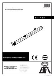
COLLEGAMENTO PER 2 MOTORI ABBINATI CON COMANDO UNICO / CONNECTIONS FOR 2 COMBINED MOTORS CONTROLLED TOGETHERCONNEXIONS POUR 2 MOTEURS ACCOUPLÉS AVEC COMMANDE INIQUE / ANSCHLUSS FÜR 2 PARALLELGESCHALTETE MOTOREN MITGEMEINSAMER STEUERUNG / CONEXION PARA 2 MOTORES ACOPLADOS CON MANDO UNICO- Eseguire solo sulla morsettiera pilota i collegamenti elettrici predisposti normalmente;- Collegare il 2° motore come indicato nello schema. (1-2) pulsante stop totale e (2-C) contatto dia<strong>per</strong>tura in fase di chiusura.- Wire the electrical connections only on the terminal board for the pilot motor in the normal;- Connect motor 2° as shown in the diagram above. (1-2) Total stop pushbutton and (2-C) contact forreopening during the closing cycle.- Effectuer seulement sur la plaque à borne pilote les branchements électriques habituellementprévus;- Brancher le 2 eme moteur de la façon indiquée dans le schéma. (1-2) Bouton-poussoir d'arrêt totalet (2-C) contact de réouverture en phase de fermeture.- Nur auf der Mastermotor-Klemmleiste die normalerweise vorgesehenen elektrischen Anschlüsseausführen;- Den 2° Motor wie auf dem hier aufgeführen Schema anschließen. (1-2) Die Drucktaste Totalstop und(2-C) den Kontakt der Wiederöffnung während der Schließung.- Efectuar sólo en la caja de bornes piloto las conexiones eléctricas predispuestas normalmente;- Conectar el 2° motor como muestra el esquema de esta página. (1-2) pulsador de stop total y (2-C) contacto de a<strong>per</strong>tura durante la fase de cierre.Morsettiera motore master (o pilota)Master (or pilot) motor terminal blockPlaque à bornes du moteur master (ou pilote)Klemmbrett Mastermotor (bzw. Steuermotor)Cuadro de bornes motor master (o piloto)Morsettiera 2° motoreMotor 2° terminal blockPlaque à bornes du 2° moteurKlemmbrett 2° MotorCuadro de bornes 2° motorL1 L2 U V W E FA FC 0 1 2 3 4 5 T1 T2 7 C S B1B2 L1 L2 U V W E FA FC 0 1 2 3 4 5 T1 T2 7 C S B1B2***1-2 2-C* DIODO IN4007 - DIODE IN 4007- 14 -
Regolazione finecorsa - Adjusting the limit switches - Reglage des fins de course - Einstellung der EndanschlägeRegulacion de los finales de carreraIn a<strong>per</strong>tura:Opening:Pour la phased'ouverture:Öffnungstellug:En la fase de a<strong>per</strong>tura:gia' regolato.pre-adjusted.prèrèglèe.voreingestellt.pre-regulado.In chiusura:Closing:Pour la phase defermeture:Stop beim Schließen:En la fase de cierre:regolare la tensionedella <strong>catena</strong> in chiusura,quindi ruotare lacamma rossa <strong>fino</strong> all'inserimentodelmicrointerruttore ebloccarla.adjust the tension on thechain when gate isclosed, then rotate thered cam until themicroswitch trips. Now,lock the cam into place.reglèr la tension de lachaîne en fermeture,puis tourner la camerouge jusq'àl'enclenchement dumicrocontact et labloquer.Kettenspannungregulieren und dann denroten Nocken bis zumEinschalten desMikroschalters drehenund blockieren.regular la tensión de lacadena en fase decierre, posteriormentegirar la leva rija hasta laactivación delmicrointerrurptor ybloquearla.Camma rossa (chiude)Red camme (closure)Came rouge (fermeture)Rote Noche (Schließen)Leva roja (cierre)MicrointerruttoriMicroswitchesMicro-interrupteursMikroschalterMicrointerruptoresCamma bianca (apre)Withe camme (a<strong>per</strong>ture)Came blanche (ouverture)Weiße Noche (Öffnen)Leva blanca (a<strong>per</strong>tura)- 15 -
NOTE / NOTES / NOTE/ HINWEIS / NOTATutti i dati riportati nel presente librettosono indicativi. La CAME s.p.a. siriserva di apportare eventuali modificheinerenti all'evoluzione tecnologicadei prodotti.All data mentioned in the present bookletare for information only. CAME SPAreserves the right to introduce changesrelating to technological improvements ofthe products.Toutes les données mentionnées dansle livret sont indicatives. CAME seréserve le droit d'apporter des modificationséventuelles par rapport àl'évolution téchnologique des produits.Alle in der vorliegenden Beschreibungangegebenen Daten dienen nur derinformation. CAME S.P.A. behält sichtechnische Andernungen vor.Todos los datos de este libreto sonindicativos. CAME s.p.a. se reserva elderecho de aportar las modificacionesproducidas por la evolucióntecnológica de los productos.CAME S.P.A.VIA MARTIRI DELLA LIBERTÀ, 1531030 DOSSON DI CASIERTREVISOCAME SUD S.R.L.VIA FERRANTE IMPARATO, 198CM2 LOTTO A/780146 NAPOLICAME FRANCE S.A.7 RUE DES HARAS92737 NANTERRE CEDEXITALIAITALIAFRANCECAME AUTOMATISMOS S.A.C/JUAN DE MARIANA, 1728045 MADRIDCAME GMBHBERGSTRASSE, 17/170825 KORNTALSTUTTGARTCAME GMBHAKAZIENSTRASSE, 9<strong>16</strong>356 SEEFELDESPAÑADEUTSCHLANDDEUTSCHLANDinternetwww.came.ite-mailASSISTENZA TECNICANUMERO VERDE800-295830N° 12 100 8953